содержание .. 50 51 52 53 54 55 56 57 58 ..
Geely Emgrand X7. Manual part - 57
2.2.7.31 DTC P0267 P0268
1. DTC
description:
DTC P0267
Cylinder No.3 Fuel Injector Circuit Low Voltage Fault
DTC P0268
Cylinder No.3 Fuel Injector Circuit High Voltage Fault
Fuel injectors operating voltage is provided by The Main Relay controlled by ECM. Battery
voltage passes through the main relay terminal No.3 to all fuel injector wiring harness connectors
terminal No.A. ECM controls Cylinder No.3 fuel injector internal ground circuit through ECM
harness connector EM01 terminal No.7. ECM monitors all fuel injector driver circuits status, if
ECM detects driving circuit status corresponding voltage is incorrect, ECM will set a fuel injector
control circuit fault DTC code.
2. Conditions For Setting DTC and The Fault Location:
DTC Code
DTC Detection
Strategy
Conditions For Setting
The DTC (Control
Strategy)
Fault Locations
P0267
Hardware Circuit
Inspection
Injector Signal Circuit
Open or Short To Ground
P0268
Hardware Circuit
Inspection
Injector Signal Circuit
Short To Power Supply
1. Sensor
Circuit
2. Sensor
3. ECM.
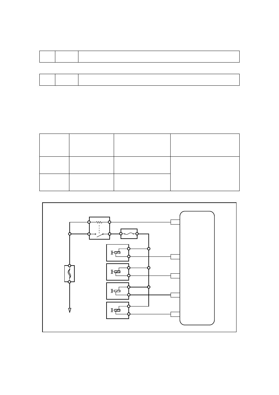
3. Circuit
sketch
主继电器ER09
87
30
86
85
EM01
44
EM01
B
A
发
动
机
控
制
模
块
蓄电池
EF4
0
EF22
1缸喷油器
3缸喷油器
4缸喷油器
2缸喷油器
6
MPR
INJA
EM01
B
A
7
INJB
EM01
B
A
25
INJC
EM01
B
A
8
INJD
NL02-0043c
4. Diagnostic
Steps:
Note: Before carrying out this diagnosis step, observe the data list on fault diagnosis tester and
Main relay ER09
Battery
1st cyinder
oil injecter
3rd cyinder
oil injecter
4th cyinder
oil injecter
2nd cyinder
oil injecter
Engi
ne
co
ntr
ol mo
dul
e
227