содержание .. 50 51 52 53 54 55 56 57 ..
Geely Emgrand X7. Manual part - 56
4. Diagnostic
Steps:
Note: Before carrying out this diagnosis step, observe the data list on fault diagnosis tester and
analyze the accuracy of the data, as these will help with quick diagnosis.
Step 1
Initial Inspection
(a) Inspect the fuel injector harness connector for damage, poor connection, aging or signs of
loosening
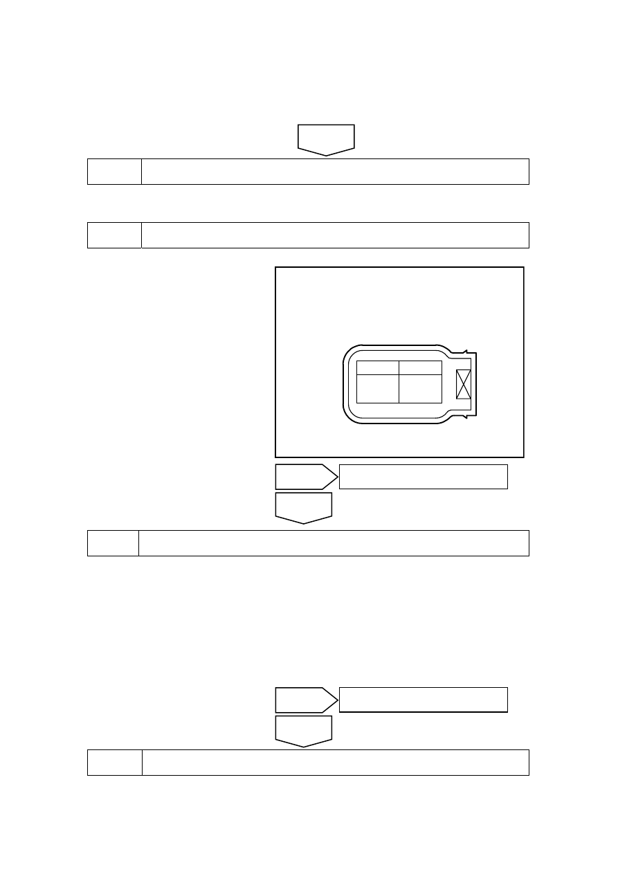
Step 2
Measure the fuel injector resistance.
(a) Disconnect the fuel injector
wiring harness connector EM15.
(b) Measure resistance between the
two fuel injector terminals.
Standard Resistance
11.4-12.6Ω @ 20 (68 )
℃
℉
(c) Connect the fuel injector harness
connector EM15.
喷油器2线束连接器 EM15
B
A
NL02-0046c
(a) Rotated ignition switch to OFF position .
(b) Disconnect cylinder No.2 fuel injector wiring harness connector EM15.
(c) Rotated ignition switch to ON position .
(d) Measure voltage between cylinder No.2 fuel injector wiring harness connector EM15 No.A
terminal and a reliable ground.
Standard Voltage: 11-14V
(e) Connect cylinder No.2 fuel injector wiring harness connector EM15.
Step 4
Inspect the fuel injector control circuit.
(a) Rotated ignition switch to OFF position .
3
Measure Fuel Injectors Working power supply
No
Go to step 5
Yes
No
Refer to 2.2.8.2 “Replacement of Fuel
Injectors” to replace the fuel injectors
Yes
Next
Oil injecter 2harness connectorEM15
223