Geely Emgrand X7. Manual part - 55


  Главная      Geely     Geely Emgrand X7 - Manual


поиск по сайту            


содержание   ..  50  51  52  53  54  55  56  ..


Geely Emgrand X7. Manual part - 55


(d) Start 

the 

engine. 

(e)  Observe whether test lamp is flashing. 

Is test lamp flashing as normal? 


Step 5 

Inspect and repair cylinder No.1 fuel injector power supply circuit. 


(a)  Rotated ignition switch to OFF 

position . 

(b) Disconnect the fuel injector 

wiring harness connector EM14. 

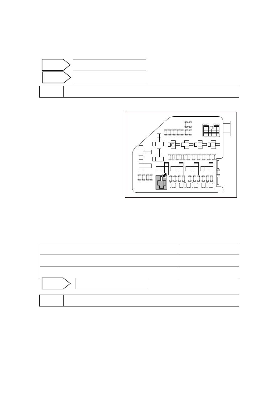
(c)  Dismantle the engine main relay. 

(d) Measure  resistance  between 

cylinder No.1 fuel injector wiring 
harness connector EM14 terminal 
No.B and engine main relay 
terminal No.30. 

ER03

85

86

87

30

30

87

86

85

ER05

30

87

86

85

ER06

30

87

87a

86

85

ER11

ER08

ER0

9

85

86

87

30

ER10

2

1

5

3

2

1

5

3

2

1

5

3

ER04

ER02

2

1

5

3

2

1

5

3

ER01

ER07

2

1

5

3

1

2

3

4

11

12

13

14

15

16

5

6

7

8

9

10

EF0

8

EF0

7

EF2

7

EF2

6

EF2

2

EF2

9

EF0

3

EF0

6

EF0

9

EF2

5

EF1

7

EF1

6

EF1

5

EF3

5

EF2

1

EF1

4

EF

01

EF

02

EF

04

EF

10

EF

1

1

EF1

8

EF2

4

NL02-0045c

(e) Measure resistance between cylinder No.1 fuel injector wiring harness connector EM14 

terminal No.B and a reliable ground. 

(f)  Install the engine main relay. 

(g)  Connect cylinder No.1 fuel injector harness connector EM14. 

Exclude the fuel injector power supply circuit fault. 

Test Items 

Standard Value 

Resistance Between EM14 (B) and Main Relay Terminal No.30 

Less than 1 Ω 

Resistance Between EM14 (B) and A Reliable Ground 

10 kΩ or higher 


Step 6 

Inspect the Cylinder #1 fuel injector control circuit. 

(a)  Rotated ignition switch to OFF position . 

(b)  Disconnect cylinder No.1 fuel injector wiring harness connector EM14. 

(c)  Disconnect ECM harness connector EM01. 

Go to step 6 

Go to step 7 

No 

Yes 

Go to step 9 

Next 

219

(d) 

Measure resistance between 
cylinder No.4 fuel injector wiring 
harness connector EM01 terminal 
No.A and ECM harness 
connector terminal No.6. Inspect 
whether the circuit is open. If 
there is no open circuit, repair the 
faulty part. 

(e) Measure resistance between 

cylinder No.1 fuel injector wiring 
harness connector EM14 terminal 
No.A and a reliable ground. 
Inspect whether the circuit is 
short to ground. Otherwise, repair 
the faulty part. 

ECM线束连接器

EM01

1

2

4

5

3

81

63

44

25

6

62

43

24 23 22 21 20 19 18 17 16 15 14 13 12 11 10

9

8

7

26

42 41 40 39 38 37 36 35 34 33 32 31 30 29 28 27

45

46

61 60 59 58 57 56 55 54 53 52 51 50 49 48 47

64

65

66

80 79 78 77 76 75 74 73 72 71 70 69 68 67

NL02-0033c

(f)  Measure voltage between cylinder No.1 fuel injector harness connector EM14 terminal No.A 

and a reliable ground. Inspect whether the circuit is short to power supply. Otherwise, repair 
the faulty part. 

Test Items 

Standard Value 

Resistance Between EM14 (A) and EM01 (6) 

Less than 1 Ω 

Resistance Between EM14 (A) and a Reliable Ground 

10 kΩ or higher 

Voltage Between EM14 (A) and a Reliable Ground 

0V 

Execute next step as per normal. 


Step 7 

Inspect the ECM Power Supply Circuits. 

(a)  Inspect whether ECM power supply circuit is normal. 

(b)  Inspect whether ECM ground circuit is normal. 


Step 8 

Replace ECM 

Refer to 2.2.7.11 Crankshaft Position Sensor (CKP) Learn to carry out the crankshaft position 
sensor learn after replacing the ECM. 


Step 9 

Use a fault diagnosis tester to confirm whether the DTC Code is stored again. 

(a)  Connect fault diagnosis tester to the diagnostic interface. 

(b)  Turn ignition switch to ON position. 

Next 

No 

Repair the faulty part. 

Yes 

Next 

ECMharness connectorEM01 

220

(c)  Clear DTC code. 

(d)  Start and run the engine at idle speed to warm up the engine for at least 5 min. 

(e)  Road test the vehicle for at least 10 min. 

(f)  Read control system DTC code again to confirm that the system has no DTC code. 


Step 10 

Troubleshooting 

5. Maintenance 

guide 

Refer to 2.3.8.5 “Replacement of Fuel Injectors” to replace the fuel injectors 

No 

Refer to 2.2.7.3 Intermittent Fault 
Inspection for intermittent fault. 

Yes 

221

2.2.7.30 DTC P0264 P0265 

1. DTC 

description: 

DTC  P0264 

Cylinder No.2 Fuel Injector Circuit Low Voltage Fault 


DTC  P0265 

Cylinder No.2 Fuel Injector Circuit High Voltage Fault 

Fuel injectors operating voltage is provided by The Main Relay controlled by ECM. Battery 
voltage passes through the main relay terminal No.3 to all fuel injector wiring harness connectors 
terminal No.A. ECM controls fuel injector ground circuit by ECM harness connector EM01 
terminal No.8. ECM monitors all fuel injector driver circuits status, if ECM detects driving circuit 
status corresponding voltage is incorrect, ECM will set a fuel injector control circuit fault DTC 
code. 

2.  Conditions For Setting DTC and The Fault Location: 

DTC Code 

DTC Detection 
Strategy 

Conditions For Setting The 
DTC (Control Strategy) 

Fault Locations 

P0264 

Hardware Circuit 
Inspection 

Injector Signal Circuit Open or 
Short To Ground 

P0265 

Hardware Circuit 
Inspection 

Injector Signal Circuit Short To 
Power Supply 

1.  

Sensor 

Circuit 

2. Sensor 

3. ECM. 

3. Circuit 

sketch 

主继电器ER09

87

30

86

85

EM01

44

EM01

B

A


蓄电池

EF4

0

EF22

1缸喷油器

3缸喷油器

4缸喷油器

2缸喷油器

6

MPR

INJA

EM01

B

A

7

INJB

EM01

B

A

25

INJC

EM01

B

A

8

INJD

NL02-0043c


Main relay ER09

Battery 

1st cyinder oil 

injecter 

3rd cyinder oil 

injecter 

4th cyinder oil 

injecter 

2nd cyinder 

oil injecter 

Engi

ne

 co

ntr

ol mo

dul

222


содержание   ..  50  51  52  53  54  55  56  ..