Geely FC. Manual part - 99


  Главная      Geely     Geely FC. Workshop Manual year 2008


поиск по сайту            


содержание   ..    92  93  94  95  96  97  98  99   100  .. 


Geely FC. Manual part - 99


Exterior/inner trim board--Inner trim board of top

29. Disassemble the pothook of sun shade [68010086]

Turn the pothook of sun shade to left for 90°, then disassemble

it.

30. Disassemble fixing pedestal of rear window sun

blind.

Use screw driver to turn the fixing pedestal of sun blind for 90°,

then disassemble it.

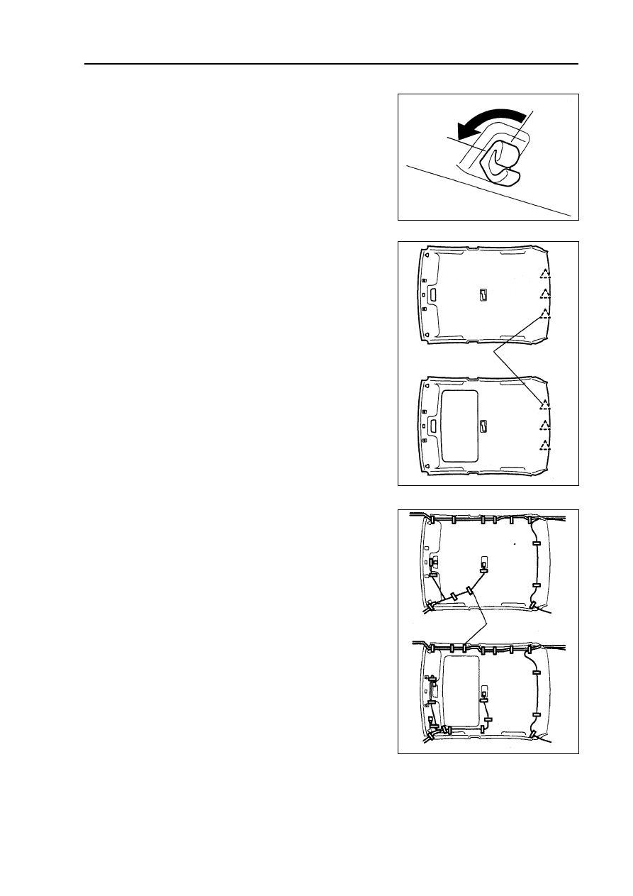
31. Disassemble trim tape of top sunroof [67010010]

32. Disassemble inner trim board of top [68010035]

(a) Use screw driver to disassemble inner trim board of top.

Hint: before using screw driver, its needled top should

be twisted by adhesive tape.

(b) Disassemble three fixing clamps and inner trim board of

top.

(c) Take out inner trim board of top from rear door.

33. Assemble inner trim board of top [68010035]

(a) Liking that shown in figure, align the mark, then fix the wir-

ing harness of top with adhesive tape.

(b) Use three fixing clamps to assemble inner trim board of top.

34. Assemble the pothook of sun shade [68010086]

Turn the pothook of sun shade to make fixing claw proturde,

then assemble sun shade.

35. Assemble rear row chair left backrest assembly

[68010078]

36. Assemble rear row chair right backrest assembly

[68010079]

37. Assemble rear row chair backrest assembly

[68010076]

Fixing
clamp

Adhesive

tape

393 

Automobile control system--Ignition switch and anti-versa lock key warning switch

Phenomenon

Ignition switch could not insert on any

position

Possible malfunction part

1. Ignition switch

2. Circuit of power supply

Reference page

394

-

Automobile control system

Ignition switch and anti-versa lock key warning switch

Malfunction phenomenon table

Inspection

1. Check the ignition switch.

Check the conduction of ignition switch joint and terminal

If the conduction does not accord with the regulation, change

the switch.

2. Check the anti-versa lock key warning switch.

If the conduction does not accord with the regulation, change

the switch.

 394 

Position of switch

Terminal connected by avometer

Regulated situation

LOCK

-

Not conduction

ACC

1-3

Conduction

ON

1-2-3, 5-6

Conduction

START

1-2, 4-5-6

Conduction

Position of switch

Terminal connected by avometer

Regulated situation

OFF (key does not insert)

-

Not conduction

ON (key inserts)

1-2

Conduction

Ignition switch/starting/charging

Electrical schematic diagram--Ignition switch/starting/charging

 395 

Electric injection control of engine

Electrical schematic diagram--Electric injection control of engine

 396 


содержание   ..    92  93  94  95  96  97  98  99   100  ..