Geely FC. Manual part - 7


  Главная      Geely     Geely FC. Workshop Manual year 2008


поиск по сайту            


содержание   ..  1  2  3  4  5  6  7  8   ..


Geely FC. Manual part - 7


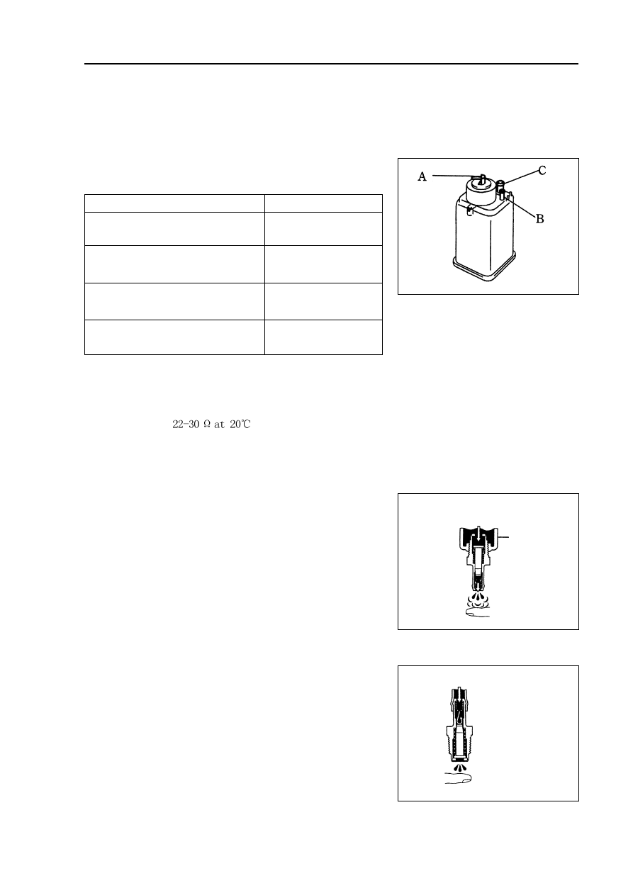
Exhaust gas control - Exhaust gas control system

3. PCV valve assembly [4G18-1014110]

(a) Blow air into valve from cylinder side and check the air is

easy to get through.

Warning: do not suck against the valve, because the

gasoline left in the valve will make you be

injured.

(b) Blow air into valve from intake manifold side and check

the air is hard to get through.

Hint: if the function does not conform to the standard, PCV

valve should be replaced.

Inspection

1. Carbon canister assembly [4G18-1129020]

Carbonl canister assembly. Check the function of carbon can-

ister according to the following tables.

Standard:

2. Carbon canister control valve

(a) For carbon canister control valve, check the conduction be-

tween terminals.

Resistance: 

(b) Check the control valve operates.

(1) Supply battery voltage to its terminal.

(2) Check air is flown as the arrow direction on valve body.

 25

Inspection Methods

Standard

 Close B hole and C hole and then

          supply vacuum to A hole

          No leakage

 Close C hole and then supply vacuum          Air flown out

                    to A hole

           from B hole

  Close C hole and then blow air                    Air flown out

               into A hole

           from B hole

          Blow air into A hole

  Air flown out from B hole

          and C hole

Clean  hose

Cylinder side

Intake manifold side

Engine mechanism

Engine assembly

Inspection

1. Check coolant.

2. Check engine oil.

3. Check battery.

4. Check air filter assembly.

5. Check spark plug [4G18-3705113].

6. Check drive belt [4G18-1307107].

Hint: do not check belt tension, because automatic tensioner is applied.

7. Check ignition timing.

(a) Warm up engine.

(b) Connect timing lamp to engine.

(c) Check ignition timing at idle speed.

Ignition timing: before top dead center 

Note: when checking ignition timing, place

transmission at neutral position.

Hint: After run the engine for 5 seconds with rotating

speed of 1000-1300rpm, check the engine could

recover to idle running.

8. Check engine idle speed.

(a) Warm up engine and run it at idle speed.

(b) Read engine rotating number in data flow with diagnostic instrument.

(c) Check idle speed.

Idle speed: about 750-850rpm

Notes:

When checking idle speed, place cooling fan at OFF position.

Turn off all auxiliary devices and air conditioner.

Engine mechanism - Engine assembly

K-line

 26 

9. Check compression pressure.

(a) Warm up engine.

(b) Remove ignition coil.

(c) Remove spark plug.

(d) Check cylinder compression pressure.

(1) Install cylinder compression pressure gauge on spark plug hole.

(2) Wide open throttle.

(3) Measure the pressure during crankshaft rotating.

Notes:

Ensure to use fully charged battery to make the rotating speed of engine reach or exceed 250rpm.

When measuring other items, please repeat steps (1) to (3).

 Finish the measurement as soon as possible.

Compression pressure:

1080kPa

Min pressure:

1000kPa

Difference among cylinders:

100kPa

(4) If the compression pressure of one or more cylinders is too low, inject a small amount of engine oil

from spark plug hole into the cylinder with low pressure, and repeat steps (1) to (3) to check

pressure.

If the pressure increases after engine oil is injected, the piston ring of this cylinder or the

cylinder has been worn or scratched.

If the pressure is still too low, the valve may be stuck or not fully closed, or the cylinder head

gasket leaks.

10. Check CO/HC.

(a) Start engine.

(b) Keep the rotating speed of engine at 2500rpm for about 180 seconds.

(c) When the engine is idle running, insert the test bar of CO/HC gauge into exhaust pipe at least 40cm.

(d) Immediately check idle speed and CO/HC concentration at 2500rpm.

Hints:

Finish test within 3 minutes.

Perform the test under 2 analog states (idle speed and 2500rpm) according to measuring meth-

ods and sequences specified by Emission Regulations.

(e) If CO/HC concentration is not within specified value, perform trouble shooting according to the

following sequences.

(1) Check the function of oxygen sensor.

(2) See possible failure causes listed in the table below, and repair and correct if necessary.

Engine mechanism - Engine assembly

27 

Engine mechanism - Engine assembly

CO

HC

Trouble occurrence

Possible causes

 28 

Normal

High

Unstable idle speed

Low

High

Unstable idle speed

(HC readings not stable)

High

High

Unstable  idle speed

(black smoke emission)

1. Ignition system malfunction

Ignition timing incorrect

 Spark plug too dirty, short circuit or clearance

incorrect

2. Valve clearance incorrect

3. Air inlet and exhaust valve leaky

4. Cylinder leaky

1. Vacuum leak:

PCV hose

Intake manifold

Throttle body

Idle speed stepping motor

Vacuum booster and pipelines

2. Fire caused by too thin mixing ratio

1. Air filter core blocked

2. PCV valve blocked

3. EFI system malfunction

Fuel pressure regulator malfunction

Water temperature sensor malfunction

Intake pressure sensor malfunction

ECU  malfunction

Injection nozzle malfunction

Throttle position sensor  malfunction


содержание   ..  1  2  3  4  5  6  7  8   ..