Geely FC. Manual part - 6


  Главная      Geely     Geely FC. Workshop Manual year 2008


поиск по сайту            


содержание   ..  1  2  3  4  5  6  7   ..


Geely FC. Manual part - 6


Fuel  - Fuel tank assembly

Fuel tank assembly

1. Take measures to prevent gasoline leaking

(see Page 14)

2. Remove rear seat cushion assembly

3. Remove rear floor repairing hole cover

4. Remove No. 2 fuel evaporation assembly

5. Remove fuel tank main fuel hose and oil return pipe

assembly

6. Remove fuel pump assembly

7. Discharge fuel

8. Remove front floor bracket

9. Remove front exhaust pipe assembly

(a) Move away carpet and remove oxygen sensor joint.

(b) Remove front exhaust pipe assembly

10.Disassemble the vent pipe of fuel hose

11.Disassemble filler pipe from fuel tank

12.Remove No. 2 fuel evaporator hose assembly

Press fuel hose joint and then pull out the hose.

Notes:

Check there is contaminant that looked like dirt around the

joint before operating and clean it off in the case of

contaminant.

Be careful of the contaminant that looked like dirt, because

fast-joint depends on o-ring to seal fuel pipe and joint.

Do not perform this operation with tools.

Do not bend or distort nylon hose.

Cover the joint with plastic bag after removing the fuel hose.

When the joint is stuck with fuel pipe, clip the hose with

fingers and rotate carefully to release the hose, and then

remove it.

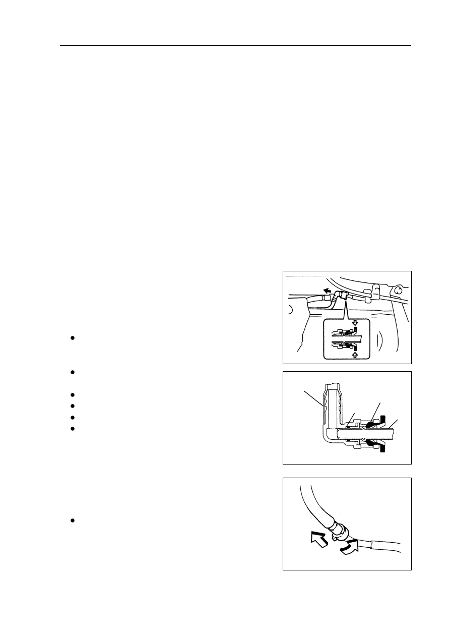
13.Disassemble fuel tank main fuel hose assembly

Clip the protrusion part of fixing ring and move lock claw toward

open direction, and then pull out the hose as shown in the

diagram.

Notes:

Check there is contaminant looked like dirt around the joint

before operating and clean it off in the case of contaminant.

 21 

Removing, installing and disassembling, assembling

Fuel pipe clip

Nylon pipe

O-ring

Pipe

Fuel  - Fuel  tank assembly

Be careful of the contaminant that looked like dirt, because

fast-joint depends on o-ring to seal fuel pipe and joint.

Do not perform this operation with tools.

Do not bend or distort nylon hose.

Cover the joint with plastic bag after removing the fuel hose.

When the joint is stuck with fuel pipe, clip the hose with

fingers and rotate carefully to release the hose, and then

remove it.

14.

Remove fuel tank assembly

(a) Remove parking brake pull cable retaining clip.

(b) Place jack under fuel tank. Remove fuel tank band harness and fuel

tank assembly.

15.

Remove fuel tank main fuel hose and oil return pipe

    assembly

16.

Remove No. 2 fuel evaporation hose assembly

17.

Remove No. 1 fuel tank gasket

18.

Remove No. 1 fuel tank protector

Remove rivet with electric drill and then remove fuel tank protector.

19.

Install No. 1 fuel tank protector

Install fuel tank protector with rivet.

20.

Install No. 1 fuel tank gasket

As shown in the diagram, install new fuel tank gasket.

21.

Install fuel tank assembly

Torque:  39 N.m

22.

Install front exhaust pipe assembly

Torque:  40 N.m

23.

Install front  floor bracket

Torque:  30 N.m

24.

Install rear floor repairing hole cover

Install rear floor service hole cover with butyl rubber cloth.

25.

Check fuel leakage (see Page 14)

26.

Check gas leakage of exhaust system

 22

Exhaust gas control

Exhaust gas control system

On-vehicle inspection

1. Check oxygen sensor.

(a) Let the engine run at idle speed for 3 minutes to ensure oxygen sensor reaches operating tempera-

ture of 350

(b) Place digital universal meter at DC voltage gear, and connect 2 terminals respectively to (gray) pin

and (black) pin of sensor, and voltage should fluctuate

quickly between 0.1-0.9V at the moment.

Warning:

Perform inspection immediately after warming

up vehicle.

If voltage change could not be confirmed,

it is necessary to heat oxygen sensor again.

Exhaust gas control - Exhaust gas control system

2. Check rotating speed after fuel cut off.

(a) Accelerate engine at least to 3500rpm.

(b) Check the operating noise of injection nozzle with listening device.

(c) When throttle is released, check the operating noise of injection nozzle recovers after stop.

3. Check fuel evaporation exhaust control system.

(a) Check the pipe clamps of connecting pipeline between

charcoal canister and carbon canister solenoid valve are

firmly clipped and check there is leakage.

(b) Check there is trouble with fuel evaporation exhaust con-

trol system with failure diagnostic instrument.

4. Visually check hose, joint and hot fin.

Check cracks, leakage and damage.

Hint: the disconnecting of engine oil level gauge, oil opening

cover and PCV hose may cause running failure of engine.

The cracks, looseness and not connecting at the intake

system between throttle and cylinder head will result in

redundant air entering and running failure of engine.

23

5. Check heater resistance of heated oxygen sensor.

(a) Uncouple oxygen sensor joint.

(b) Place digital universal meter at ohm gear, and connect 2 terminals respectively to 1# (white) pin  and

2# (black) pin, and the resistance under normal temperature is 1 6

6. Check fuel tank cover.

Visually check fuel tank cover and gasket are distorted or damaged.

Exhaust gas control - Exhaust gas control system

 24 

Oxygen sensor

Main relay


содержание   ..  1  2  3  4  5  6  7   ..