Geely FC. Manual part - 4
 

  Главная      Geely     Geely FC. Workshop Manual year 2008


поиск по сайту            


содержание   ..  1  2  3  4  5  ..


Geely FC. Manual part - 4


Engine control system·- Throttle body assembly

Throttle body assembly

Removing, installing and disassembling, assembling

1. Discharge coolant (see Page 73).

2. Remove air cleaner hose assembly.

3. Remove engine plastic hood components [4G18-1000310].

4. Remove throttle pull cable assembly.

5. remove throttle body assembly [4G18-1008240].

(a) Uncouple throttle position sensor joint and stepping motor joint.

(b) Disassemble ventilation hose.

(c) Remove 2 bolts and throttle control pull cable bracket.

(d) Remove 2 preheating water inlet and outlet hoses of throttle.

(e) Remove 2 bolts and 2 nuts, and remove throttle body from intake air manifold.

6. Remove stepping motor of throttle body [4G18-3600070].

Remove 3 screws and stepping motor.

7. Install stepping motor of throttle body.

Install stepping motor.

8. Install throttle body assembly.

(a) Install new seal gasket on intake air manifold.

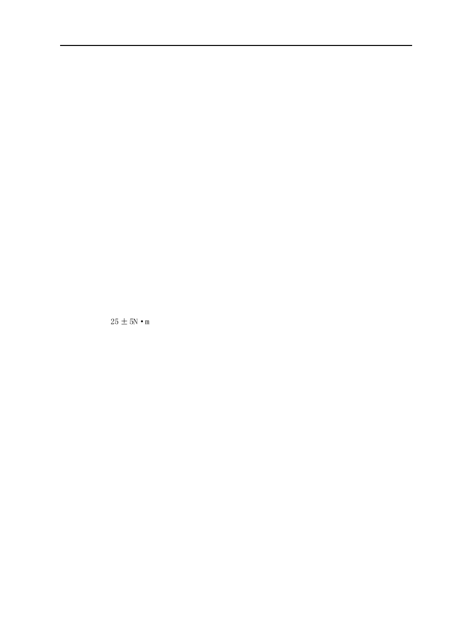
(b) Install throttle body, 2 bolts and 2 nuts.

Torque: 

9. Refill coolant.

10.Check there is leakage with coolant.

 13

Fuel

Fuel system

Precautions

1. Before repairing fuel system, uncouple battery negative (-) wire at first.

2. When operating on fuel system, do not smoke or repair near fire area.

3. Do not let gasoline come into contact with rubber or leather parts.

4. Take measures to prevent gasoline leaking.

(a) Uncouple electric fuel pump joint.

(b) Start engine and turn ignition switch to LOCK position

after the engine flames out.

(c) Uncouple battery negative (-) wire.

(d) Couple electric fuel pump joint.

5. Fuel system

(a) There will be a great amount of gasoline flowing out

when disassembling high-pressure fuel pipe,

therefore, it is required to observe the following

procedures.

(1) Take measures to prevent gasoline leaking.

(2) Disassemble fuel pipe.

(3) Completely discharge the oil in fuel pipe.

(4) Cover the fuel pipe with plastic bag to avoid pipe

damage and foreign matters entering.

(5) Place a container under the joint.

(b) When removing and installing injection nozzle, always

observe the following precautions.

Fuel-Fuel system

 14

Fuel-Fuel system

(1) It is not allowed to use o-ring repeatedly.

(2) When installing o-ring, always be careful to avoid dam-

aging o-ring.

(3) Before installing, coat o-ring with spindle oil or gasoline.

It is not allowed to coat with engine oil, gear oil or

brake fluid.

(c) As shown in the diagram, install injection nozzle to oil feed

pipe and cylinder head.

Before installing, ensure that spindle oil and gasoline are

coated at the contact position between o-ring and oil feed

pipe.

(d) When disassembling oil feed pipe, always observe the fol-

lowing precautions.

(1) Remove oil feed pipe clips.

(2) Remove oil feed hose.

(3) Cover oil inlet of fuel distribution pipe with plastic bag

to avoid foreign materials entering the fuel distribution

pipe.

injection nozzle

6. Inspection of fuel leakage

(1) After completing maintenance, check there is leakage with the whole fuel system.

(2) Connect hand-held tester to diagnostic joint.

(3) Turn ignition switch to ON and turn main switch of hand-held tester to ON.

(4) Switch hand-held tester to function test state.

(5) For further details, please see hand-held tester operating instruction.

(6) If there is no hand-held tester, connect battery anode and cathode to electric fuel pump joint.

(7) Ensure that there is no leakage with all parts of electric fuel pump.

(8) Turn ignition switch to LOCK.

(9) Disassemble hand-held tester from diagnostic interface joint.

15

o-ring

oil feed pipe

oil feed pipe

o-ring

washer

Correct

Wrong

On-vehicle inspection

1. Inspection of fuel pump function

(a) Connect hand-held tester to diagnostic joint.

(b) Turn ignition switch to ON and turn main switch of hand-

held tester to ON.

Note: do not start the engine.

(c) Switch hand-held tester to function test state.

(d) For further details, please see hand-held tester operating

instruction.

(e) If there is no hand-held tester, connect battery positive (+)

wire to P+ terminal and negative (-) wire to P- terminal.

2. Inspection of fuel pressure

(a) Preparation of inspection.

Purchase new fuel hose and take out fuel pipe joint.

(b) Take measures to prevent gasoline leaking.

(c) Disassemble fuel pipe clamp at fuel pipe joint of fuel rail

component.

(d) Disassemble fuel hose from fuel pipe of fuel rail component.

(e) As shown in the diagram, install special tool (pressure

gauge) with special tool and fuel pipe joint.

(f) Check there is fuel leakage.

(g) Start engine.

(h) Measure the fuel pressure at idle speed state.

Fuel pressure: 390~400Pa

(i) Take measures again to prevent gasoline leaking.

(j) After measuring the fuel pressure, remove special tool.

(k) Connect back fuel hose.

(l) Install fuel hose fixing clip to fuel pipe joint.

(m)Check there is fuel leakage.

Fuel-Fuel system

Special

tool

 16 


содержание   ..  1  2  3  4  5  ..