Chery A15 / 480 LHD model. Manual - part 4


  Index      Chery     Chery A15 / 480 LHD model - service repair manual


Search            


Content   ..  1  2  3  4  5  ..


Chery A15 / 480 LHD model. Manual - part 4


return  back  within  10  min,  it  indicates  that 
the system is normal and the refrigerant can 
be charged into the system. 

(6)  Restart  the  vacuum  pump,  and  turn  on  the 

low-pressure 

valve 

of  the 

manifold 

pressure  gauge  to  continuously  vacuumize 
15  min.  Then,  turn  off  the  low-pressure 
valve  to  stop  vacuumizing,  and  prepare  for 
charging the refrigerant. 

 
7. Refrigerant Recycling Equipment Operation Guide 
Recycle 

the 

refrigerant 

from 

the 

refrigeration device 
When  the  refrigerant  is  removed  from  the 
refrigeration  device  under  the  following 
conditions,  a  recycling  receiver  shall  be 
applied to recycle the refrigerant.   
Before the components on the refrigerant pipe 
are replaced. 
When  moisture  or  air  enters  into  the 
refrigerant pipe. 
When  excessive  refrigerants  are  charged  into 
the system. 


WARNING: 

(1) 

When  the  recycling  receiver  is  required,  take  care  to  operate  it  according  to  the 

requirements of device manufacturer's instructions. 

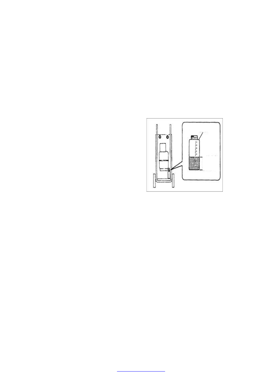
(2) After the  completion  of  recycling  work, measure the  level  of compressor oil  recycled  so 

that the same quantity of oils are added to the refrigeration device in the future. 

Operation guide for refrigerant recycling receiver 

1.  Install the manifold pressure gauge kit on the service valve. 

2.  Recycle the refrigerant from the refrigeration device. 

(a)  Connect the intermediate hose to the recycling receiver. 

(b)  Operate the recycling receiver. 

(c)  Open the manual high- and low-pressure valves on the refrigeration pressure gauge kit. 

1.  After the completion of recycling work, turn off the recycling receiver. 
2.    Remove the manifold pressure gauge kit from the service valve.


OIL BOTTLE 

DRAINED 
OIL 
QUANTITY 


A/C SYSTEM COMPONENTS 

1. Function description of A/C control panel 


2. Removal/Installation of A/C compressor 

(1)  Drain  off  the  coolant  (see  the  coolant 

recycling procedure) 

(2)  Loosen the drive belt, and remove it 

(3)  Remove the air filter and generator 

(4)  Remove the refrigerator pipes, and pull out 

the electromagnetic clutch connector 

(5)  Remove  the  two  bolts  (M10*110)  (with 

tightening  torque  of  45±5N·m)  used  to 
secure the compressor and its support. 

(6)  Install it in the reverse order of removal 


Compressor 

Position 

and 

Related 

Performance Parameters: 

Chery  A15LHD  with  the  electronic  fuel 
injection  type  engine  adopts  the  SD7V16  type 
compressor,  the  performance  parameters  of 
which are shown in the table below. 


(1) Blower switch 

(2) Temperature control switch 

(3) Air-flow distribution switch 

(4) A/C ON/OFF 

(5) Internal circulation switch


Swash Plate 

Number of cylinders 

Cylinder diameter (mm) 

29.3 

Travel (mm) 

max 

min 


34.2 

2.2 

Displacement (cm³/r) 

max 

min 


161.3 

10.4 

Allowable  maximum  instantaneous  speed 
(r/min) 

8000 

allowable 

maximum 

continuous 

speed 

(r/min) 

7000 

Coolant 

R134a 

Refrigerant oil (cm

3

115±15 

Electromagnetic clutch mass (kg) 

2.2 

Rated voltage (V) 

12 

Rated power (W) 

48 


The  compressor  is  driven  by  engine  crankshaft  pulley  via  the  M belt.  When  the  shift  lever 
on  the  A/C  control  mechanism  is  shifted  to the  refrigeration  position,  the  electromagnetic 
clutch  of  A/C  compressor  engages,  and  the  compressor  pulley  make  the  main  shaft  and 
swash  plate  rotate  and  then  pull  the  rocking  plate  to  swing.  The  swinging  of  the  rocking 
plate  pushes  the  piston  to  move,  which  creates  the  air  pumping  effect  to  compress  the 
low-temperature  and  low-pressure  air-state  coolant  into  the  high-temperature  and 
high-pressure air-state coolant. 

The motion parts of compressor are lubricated using the sputtered refrigerant oil and the oil 
in coolant. During the operation of compressor, due to the rotation and swing of the swash 
plate, the refrigerant oil will be sputtered to anywhere. In addition, due to the intersolubility 
of  coolant  and  oil,  when  the  coolant  flows  into  the  compressor,  it  also  carries  a  part  of 
refrigerant oil which is available to lubricate the motion parts inside the compressor. 

ADJUSTMENT OF ELECTROMAGNETIC CLUTCH 

1. Use a thickness gauge to measure the clearance between the platen and  A/C compressor 

pulley. 

2. Check whether the clearance is in the range specified by the technical specification. 

• If it is found that the result doesn’t conform to the requirement of technical specification, 

remove the platen, and use one or several shims to adjust the clearance. 

Clearance: 

0.6mm±0.2mm


3. Removal/Inspection of condenser 

(1). Drain  off  the  coolant  from  the  system  (see  the 

coolant recycling procedure) 

(2). Remove  the  front  bumper  and  headlamp  crossbeam 

assy. 

(3). Remove  the  fluid  reservoir  and  the  refrigeration 

pipes connecting to the condenser. 

Check the condenser: 

(1) Check the crack, damage or oily fluid leakage. 

·Replace the condenser if any failure above occurs. 

(2) Check whether the fender position is blocked by dust 
or not. 

·Clean it if blocked. 

(3) Check the bent condition of fender position. 

·Use a flat headed screwdriver to straighten the fender 


Content   ..  1  2  3  4  5  ..