Geely Emgrand X7. Manual part - 678


  Главная      Geely     Geely Emgrand X7 - Manual


поиск по сайту            


содержание   ..   674  675  676  677  678  679 ..


Geely Emgrand X7. Manual part - 678


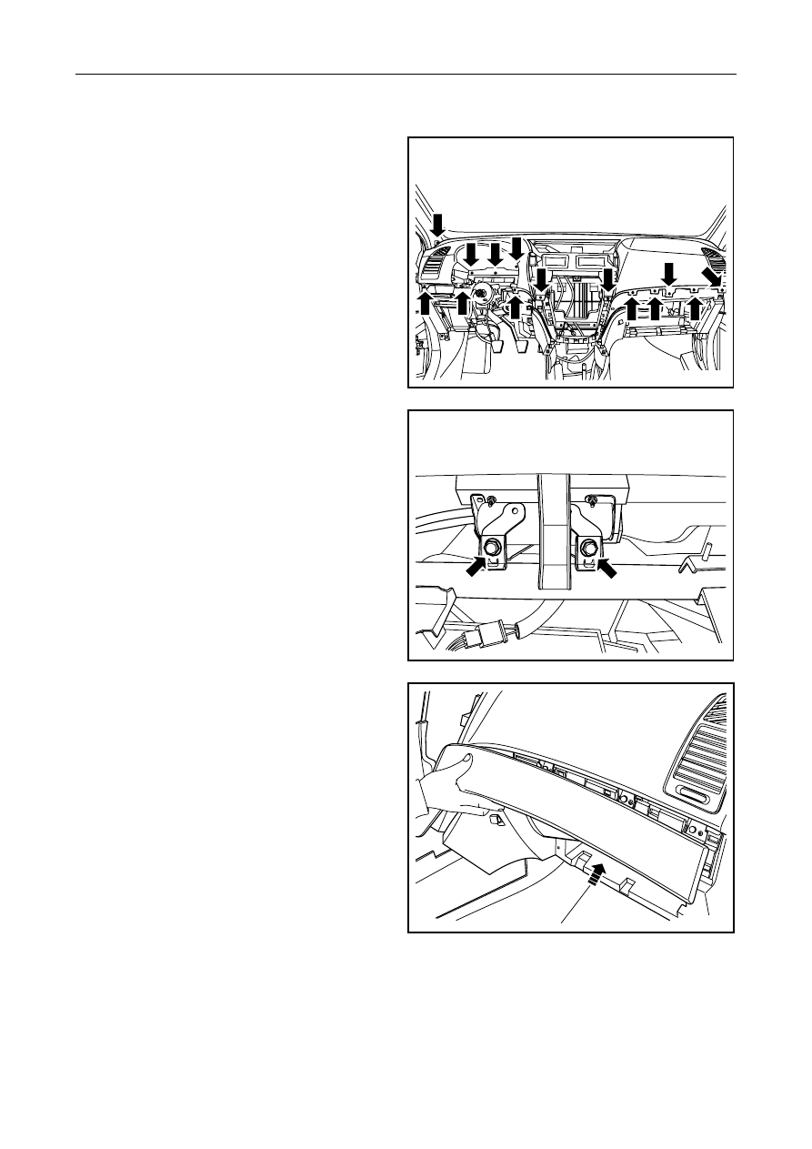
4.   Install 4 fixing bolts and 11 screws of upper 

cover of instrument table, and tighten them. 

Torque: 20Nm (Metric) 14. 8lb-ft(English system) 


NL12-0234b

5.    Install and tighten 2 bolts for the passenger side 

airbag. 

Torque: 24Nm (Metric) 17. 8lb-ft(English system) 


NL12-0233b

6.    Install the right dashboard trim panel. 


NL12-0238b

2711


7.  Connect the anti-theft indicator lamp and 

headlight height adjustment switch harness 
connectors. 


NL12-0239b

8.    Install the instrument panel switch assembly. 


NL12-0240b

9.    Install the harness connector of the knee airbag. 


NL12-0500b

2712


10.   Install instrument table left lower trimming plate, 

tighten 2 fixing screws and 2 bolts. 

Torque: 20Nm (Metric) 14. 8lb-ft(English system) 

Notes: 

2 fixing screws only need to be installed in the vehicle 
without knee SRS. 

11.   Install grove box of instrument desk. 

12.   Install front left right post trim plate 

13.   Install environment and sun sensor. 

14.   Install multi-functional instrument. 

15.   Install the audio head unit. 

16.   Install central vent port panel. 

17.   Install the air-conditioning control panel. 

18.  Install the combination instrument cover and 

combination instrument assembly. 

19.   Install combined lamp light switch and upper and 

lower protective plate. 

20.  Assemble steering wheel 

21.  Install the auxiliary instrument panel assembly. 

22.  Connect the battery negative cable. 

NL12-0229b


2713


12.8.3.2 Auxiliary instrument panel replacement 

Dismantlement Procedure 

Warning! 

Warning: Refer to "Warning on Battery 
Disconnection" in "Warnings and Precautions". 

Notes: 

Please dismantle the trim panel assembly with a 
special-purpose body repair tool; otherwise this will 
easily cause the trim panel to be damaged. 

1.   For disconnection of negative cable of battery, 

refer to 2.11.8.1 Disconnection procedures of 
battery cable.


Connecting Procedure: 

2.  Dismantle front ashtray panel of auxiliary 

instrument panel. 

NL12-0112b

3.    Dismantle standby power supply and disconnect 

wire harness connector. 


NL12-0119b

4.   Separate the shift mechanism decoration panel 

from the floor console. 

NL12-0241b

2714


содержание   ..   674  675  676  677  678  679 ..