Geely Emgrand X7. Manual part - 428


  Главная      Geely     Geely Emgrand X7 - Manual


поиск по сайту            


содержание   ..   424  425  426  427  428  429 ..


Geely Emgrand X7. Manual part - 428


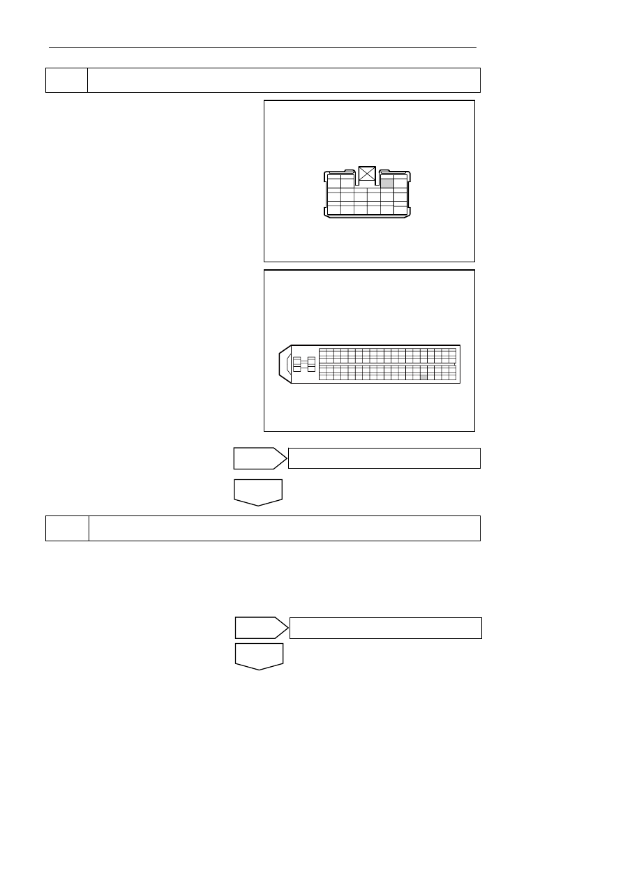
Inspect the communication between engine cabin fuse box and ECM. 

(a) Inspect whether the engine hood fuse box 

harnesses connector EN25 terminal 3 and ECM 
harnesses connector EN01 terminal 10 are 
connected. 

(b)  Make sure that engine hood fuse box    harnesses 

connector EN25 terminal 3 and ECM    harnesses 
connector EN01 terminal 10 are connected well. 

Standard resistance: less than 1 Ω 

Does the A/C clutch operate normally? 

NL08-2007b

EN25发动机舱保险丝盒线束连接器

1

2

3

4

5

6

7

8

9

10

11 12 13 14 15 16


NL08-2008b

EN01发动机控制模块线束连接器

1

2

4

5

3

81

63

44

25

6

62

43

24

23

22

21

20

19

18

17

16

15

14

13

12

11

10

9

8

7

26

42 41

40

39 38 37

36

35 34 33

32

31 30 29

28

27

45

46

61

60 59

58

57 56 55

54 53 52

51

50 49

48

47

64

65

66

80 79

78

77 76 75

74

73 72 71

70

69 68 67


10 

Inspect the ECM circuit. 

(a)  Check ECM power supply and grounding circuit. 

(b) Make sure that ECM power supply and 

grounding are connected normally. 

Does the A/C clutch operate normally? 


No 

Yes 

The system is normal. 

No 

Yes 

The system is normal. 

EN25 engine compartment fuse box harness 

connector


EN01 engine control module harness connector


1711


11 Replace 

ECM 

(a)  Replace ECM and refer to 2.2.8.6 "replacement 

of engine control module". 

Does the A/C clutch operate normally? 


12 

Replace A/C pressure switch. 

(a)  Replace A/C pressure switch. 

Does the A/C clutch operate normally? 


13 

Detect the communication of the A/C control module and the A/C pressure switch. 

(a) Inspect whether A/C control module  harnesses 

connector IP16 terminal 10 and A/C pressure 
switch  harnesses connector EN17 terminal 2 
are connected. 

(b)  Make sure that A/C control module  harnesses 

connector IP16 terminal 10 and A/C pressure 
switch  harnesses connector EN17 terminal 2 
are connected normally. 

Does the A/C clutch operate normally? 

14

13

15 16 17 18 19 20 21 22 23 24

1

2

3 4

5

6

7

8 9 10 11 12

空调控制模块线束连接器

IP16

空调压力开关线束连接器

EN17

2

1

3

4

NL08-2009b


14 

Inspect the communication of the ECM and the A/C pressure switch. 

No 

Yes 

The system is normal. 

No 

Yes 

The system is normal. 

No 

Yes 

The system is normal. 

IP16 air conditioningcontrol module harness 

connector


EN17 air conditioning pressure switchharness 

connector


1712


(a)  Check if ECM harness connector EN01 terminal 

40 connect with A/C pressure switch harness 
connector EN17 terminal 4 

(b)  Make sure that ECM    harnesses connector EN01 

terminal 40 is well connected with A/C pressure 
switch    harnesses connector EN17 terminal 4. 

Does the A/C clutch operate normally? 

空调压力开关线束连接器

EN17

2

1

3

4

1

2

4

5

3

81

63

44

25

6

62

43

24 23 22 21 20 19 18 17 16 15 14 13 12 11

10

9

8

7

26

42 41

40 39 38

37

36 35 34

33

32 31 30

29

28 27

45

46

61

60 59

58

57 56 55

54 53 52

51

50 49

48

47

64

65

66

80 79

78 77 76

75

74 73 72

71

70 69 68

67

发动机控制模块线束连接器

EN01

NL08-2010b


(a)  Replace A/C control module, refer to

 8.2.8.1 A/C 

control panel 

Confirm the completion of repair. 


16 

The system is normal. 


15 

Replace A/C control module. 

Next 

No 

Yes 

The system is normal. 

EN01 engine control module harness connector


EN17 air conditioning pressure switchharness 

connector


1713


8.2.7.9 AC Blower Does Not Work 

Circuit diagram: 

See Electrical appliance schematic diagram. 

Diagnostic steps: 

Carried out A/C self- inspection process , 

(a)  Carried out A/C self- inspection process, refer to 

8.2.7.5 Self- inspection controller. 

(b)  Repair and check all indicator fault by self 

Does the A/C blower operate normally? 


Inspect the blower relay (indoor fuse relay box R03). 


A. Perform the maintenance procedures according to 

the following list of symptoms. 

NL08-2021b

IR05

8 5

8 6

8 7

3 0

IR02

8 5

8 6

8 7

3 0

IR07

8 5

8 6

8 7

3 0

4

IR01

2

1

5

3

4

2

1

5

3

IR04

IR03

8 5

8 6

8 7

3 0

IF 1 4

IF
2

9

IF
3

2

IF
3

3

IF
3

4

IF
3

5

IF
1

8

IF 1 3

IF 11

IF
2

5

IF
2

6

IF
2

7

IF
2

0

IF
0

1

IF
0

2

IF
0

3

IF
0

4

IF
0

5

IF
0

6

IF
2

1

IF
2

2

IF
2

3

IF

3

0

IF1
2

IF1
6

IF1
7


Symptoms 

Suspected fault part 

Maintenance scheme 

Terminal 30 of the blower relay 
has no battery voltage. 

The fuse IF17 (40A) is blown. 
 harnesses fault 

Repair the    harnesses. 
Replace fuseIF17 

Terminal 85 of the blower relay 
has no battery voltage. 

The fuse IF25 (10A) is blown. 
 harnesses fault 

Repair the    harnesses. 
Replace fuseIF25 

Terminal of the blower 
assembly IP11-1 has no battery 
voltage. 

The blower relay faults. 
 harnesses fault 

Replace blower relay 
Repair the    harnesses. 

Terminal 86 of the blower relay 
is in bad contact with ground. 

 harnesses fault 
Ground point G8 faults. 

Repair the    harnesses. 
Repair the fault of poor grounding of 

No 

Yes 

The system is normal. 

1714


содержание   ..   424  425  426  427  428  429 ..