Geely Emgrand X7. Manual part - 425


  Главная      Geely     Geely Emgrand X7 - Manual


поиск по сайту            


содержание   ..  422  423  424  425  426  ..


Geely Emgrand X7. Manual part - 425


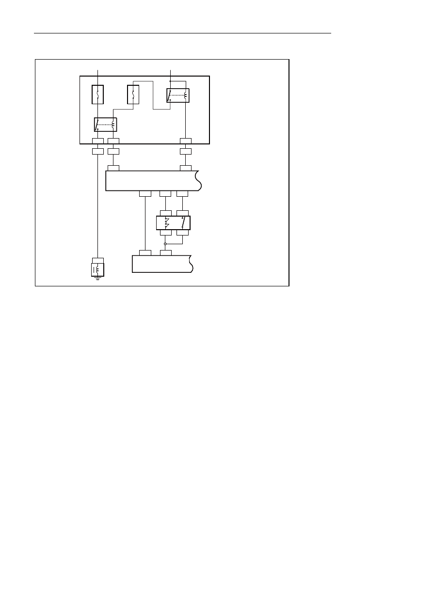
8.2.6.2 A/C system circuit sketch 

6

6 EN25

1 EN06

10 EN01

CA22 3

3 EN25

8

8

44 EN01

EN25

CA22

10A

E

F0

9

15A

E

F2

1

3

1

5

B/W

2

85

ALT

空调继电器

空调压缩机

离合器

发动机

主继电器

发动机舱
保险丝继电器盒

BAT

30

86

87

CA22

21 IP16

10 IP16

18 EN01

3

EN17

79 EN01

4

EN17

40 EN01

空调
压力
开关

1

EN17

2

EN17

PRESSURE

AC空调控制面板(自动)

RPM

ECM

ACREQ

MIDAC

NL08-2001b


Engine compartment 

fuse relay box 

Engine 

Main 

relay

Air conditioning 

relay 

Air conditioning 

pressure switch

Air 

conditioning 

compressor 

clutch 

ACAir condition control 

panel (Auto) 

1699


1 IP11

20

5

18

19

M

40

A

IF1

7

10

A

IF2

5

30

85

87

86

鼓风机

继电器

鼓风机

ALT

IG1

IP11

B

B

B

20

18

19

B

B

B

空调控制面板(自动)

室内保险丝
继电器盒

NL08-2002b


Indoor fuse 

relay box 

Blowerrelay

Blower 

Air condition control panel (Auto)

1700


23 IP16 24 IP16

5

2

3

22 IP16

12 IP16

7 IP16

6 IP16

11 IP16

15

A

IF

06

空调控制面板(自动)

至后除霜

开关
IP06-4

至组合

仪表
IP02-2

至后除霜

继电器

室内保险丝
继电器盒

IP+B

10

A

IF

25

IG1

至背光照明
BCM IP49-8

阳光传感器

环境温度传感器

IP16

IP16

IP16 9 IP16

1

2

2

CA05

CA05

IP04

1

IP04

13 IP16 14 IP16 1 IP16

GND

GND

GND

21 IP16

10 IP16

18 EN01

DEFOG SW

DEFROST

OUT PUT

VEHICLE SPEED

ILL+

SUN SENS

GND

GND

AMB SENS

B+

IG

IG

3

EN17

79 EN01

4

EN17

40 EN01

空调

压力

开关

1

EN17

2

EN17

ECM

ACREQ

MIDAC

PRESSURE

RPM

NL08-2003b


Indoor fuse 
relay box 

Ai

r condi

tioni

ng 

pr

essur

e swit

ch


Ambient 

temperature sensor


Solar sensor 

Air condition control panel (Auto)

To Backlight 

lighting BCM 

IP49-8 

To rear 

defrost 

switchIP06-4

To rear 

defrostrelay

To 

Combination 

instrument 

IP02-2 

1701


8.2.7 Diagnostic information and procedures 

8.2.7.1 Diagnosis descriptions 

Refer to 8.2.2 Description and operation, get familiar with the system functions and operation before starting 
system diagnosis, so that it will help to determine the correct diagnostic steps, more importantly, it will also help 
to determine whether the situation described by the customer is normal. 

8.2.7.2 Visual inspection 

Inspect the after-sales optional device which may affect the performance of A/C system. 

Inspect the parts and circuits of A/C system which are accessible and easy to be seen, to find out whether there is 
any damage or possible cause to fault. 

Inspect the pipelines which are accessible and easy to be seen, to find out whether there is any leakage of A/C 
system. 

8.2.7.3 List of A/C control module terminals 

NL08-2004b

14

13

15 16 17 18 19 20 21 22 23 24

1 2 3 4 5 6 7 8 9 10 11 12

IP16空调控制模块线束连接器


Note: unless otherwise specified, GND is 0V or close to 0V. 

Terminal 
No . 

Terminal definition 

Diameter/color 

Terminal 
status 

Specified conditions 
(voltage, current, 
waveform, etc.) 

Lamplet (-) 

0.3B 

Output 

GND DC signal 

Sensor Grounding 

0.3B 

Output 

GND DC signal 

Sunlight sensor 

0.3B 

Input 

0~+5v DC signal 

4 - 


Outside Temperature Sensor 

0.3V/W 

Input 

0~+5v DC signal 

Speed Detection Signal 

0.3B/R 

Input 

Pulse signal 

Rear defrost signal output 

0.3R/L 

Output 

A627 A628 DC signal 

8 - 


Sensor Testing Signal (+5) 

Output 

+5v DC signal 

10 

A/C signal 

0.3L 

Output 

A627 A628 DC signal 

11 

Battery 

0.3R/Y 

Input 

A627 A628 DC signal 

IP16 air conditioningcontrol module harness 

connector


1702


содержание   ..  422  423  424  425  426  ..