Geely Emgrand X7. Manual part - 422


  Главная      Geely     Geely Emgrand X7 - Manual


поиск по сайту          


содержание   ..   420  421  422  423  ..


Geely Emgrand X7. Manual part - 422


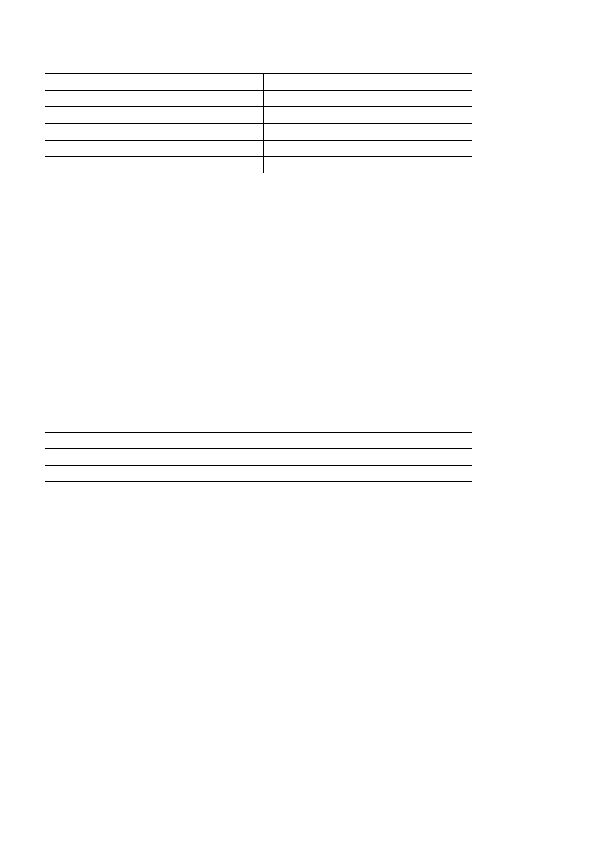
The air allocation model and actuator position (feedback voltage): 

Mode (air distribution mode) 

Actuator feedback voltage (V) 

Air supply to face 

0.3 

Both-way (surface blowing and foot blowing) 

1.4 

Air supply to feet 

2.5 

Mix (blow foot and defrost) 

3.6 

Defrost 4.7 

In the automatic control mode, the air distribution mode is controlled by a number of input signals. Input signal 
includes set value, in-vehicle temperature, out-vehicle temperature and sunlight intensity etc. When an air-out 
mode key is operated, the system will be automatically converted into the manual mode from the automatic mode. 

Certain limit of the A/C system may cause that the comfort is unable to reach under exceptional circumstances. 
The A/C control module selects one proximal mode to display on the LCD at that time. 

5.  Internal-outside circulation control 

The user can choose outside circulation mode or inside circulation mode: 

1.  Under outside circulation mode, open outside circulation vent port and close inside circulation vent. 

2.  Under interior circulation mode, interior circulation vent port must open, and exterior circulation vent port 

must close. 

In the automatic control mode, the ventilation is controlled by a number of input variables. Input signal includes 
set point, in-vehicle temperature, out-vehicle temperature and sunlight intensity etc. In the automatic control mode, 
there are two throttle positions (outside circulation and internal circuit) for ventilation. 

Under manual control mode 

– 

Press down the fresh air button, venting valve keeps the outside circulation mode 

– 

Press down the circulation button, venting valve keeps the inside circulation 

The ventilation model and actuator position (feedback voltage) 

Ventilation 

Actuator feedback voltage (V) 

Fresh air 

0.3 

Circulation 4.7 

6. Defrost 

control 

The defrosting button is used to activate the front windshield defrosting function. At this time, the fan speed 
reaches the maximum level and the internal circulation is canceled (as the internal circulation may affect the 
defrosting effect) and the compressor enabling request is made. 

– 

Air volume allocation models is defrost 

– 

Venting valve is in the new air position 

– 

A/C is "ON", and A/C mark display (only if outside temperature is too low) 

If the external temperature is too low when defrosting, the automatic controller does not send out a compressor 
start-up request signal to the engine control unit. 

When the starting temperature is in the temperature setting zone, A/C ON is optimized. 

1687


NL08-2033b

A/C Output Off

A/C Output On

C

C

0


– 

AUTO mark is "OFF" 

– 

DEF mark display. 

Under nay working condition (automatic, manual and off), the system immediately operates under the defrosting 
state in the case of pressing the defrosting button. After the defrosting is deactivated, the system will immediately 
return to the status before defrosting (automatic, manual and shut down). 

In a defrosting mode, the blower speed is adjusted to the maximum, so as to ensure that the blower voltage is 
above 6.5V. The throttle is regulated to blow glass, and the air-out temperature is increased by constant 
compensation. Start the compressor and open the circulation throttle to the outside circulation. Under the 
defrosting state, press the air speed regulating button to correspondingly increase or reduce the air speed. Keep 
defrosting in the working condition, continually operate the compressor, and keep glass blowing in the air-out 
mode. 

Rear defrosting function 

The rear defrosting is controlled upon the engine speed signal and the time check function. If the engine speed is 
lower than 750rpm, the controller shall cut off the rear defrosting output. In addition, the controller also has a time 
check function to inspect the running tie of rear defrosting; and if the running time reaches 12m, cut off the output 
of rear defrosting. LCD displays corresponding identification during rear windshield defrosting. The user can 
press the rear defrosting key again to cancel the rear defrosting function. 

7. A/C 

control 

The automatic control module provides an A/C request signal to the engine control unit to control the A/C 
compressor clutch through the engine control unit. Press down the A/C button when the system is closed; and the 
A/C can also not be opened if the blower is not opened. 

Automatic control 

When pressing down an AUTO key, select A/C automatic mode. In the automatic mode, A/C opening is 
controlled by a number of input conditions: driver set value, in-vehicle temperature, out-vehicle temperature and 
sunlight intensity, etc. When A/C opens, the display screen displays A/C identification. 

Manual control 

The A/C can be turned on or off with the A/C button. 

Closing of the compressor clutch 

When the heat in air is transmitted to the evaporator core, moisture in air will be condensed on the outer surface of 
the evaporator core to for water to flow outside. The evaporator is equipped with a temperature sensor to prevent 
from freezing. The sensor measures the surface temperature of the radiating fin on the evaporator, the compressor 
clutch will not continue to work if the temperature is lower than 2.5℃. 

Phase difference:3°C


1688


If the temperature is increased to above 4℃, the compressor will start working again. In the system with 
automatic temperature control, the sensor signal is firstly transmitted to the controller, and then is transmitted to 
the A/C pressure switch through a special line; if the A/C pressure meets requirements, the corresponding air 
starting signal is transmitted to the engine control unit, and the engine control unit controls the on/off of the 
compressor clutch. In fact, the automatic A/C controller will always provide a, "A/C ON" signal to the engine 
control unit through a simulating resistance (5kΩ) and controls the closing of "A/C". 

7.  Auto and manual work status 

The system has three states of automatic (AUTO), manual (MANU) and off (OFF). 

The following functions are realized under the manual state: 

– 

Manual wind speed adjustment 

– 

Manual air-out mode control 

– 

Manual inside and outside circulation control 

Under the automatic state, the following functions are automatically regulated by the controller according to the 
driver set value, the in-vehicle temperature, the out-vehicle temperature and the sunlight intensity: 

– Temperature 

automatic 

control 

– 

Wind speed automatic control 

– 

Air volume allocation models automatic control 

– 

A/C automatic control 

– 

Inside and outside circulation automatic control 

Screen display with auto-mode 

– 

AUTO mark display on the screen 

– 

Driver temperature setting value display on the screen 

– 

Wind speed and fan mark display in the screen 

– 

Air volume allocation models display in the screen 

– 

A/C mark displays in the screen 

– 

Inside and outside circulation mark display in the screen 

AUTO mark can only be shown in screen in automatic mode. When selecting OFF (all A/C systems are closed), 
the automatic mode is canceled. 

Part of the following operation can cancel the automatic mode: 

– 

Manual adjusting blower air speed (AUTO do not display) 

– 

Manual adjustment air volume allocation models (AUTO do not display) 

– 

Manual selecting A/C (AUTO do not display) 

– 

Manual selecting inside and outside circulation (AUTO do not display) 

– 

Defrost function option 

Notes: 

The function without manual regulation still automatically controls. 

The AUTO mode will be re-enabled when the AUTO key is pressed. 

System stop 

1689


Close system (blower, compressor and indicator lamp etc.). All throttles keep the position prior to closing the 
system. 

The LCD display screen is on and the mode and ventilation function can be operated manually. 

– 

Reset temperature: freeze and memory setting (not display in the screen). 

– 

A7-A/C: closed and stored setting value (do not display in the screen 

– 

Mode: Keep setting status and mode may be operated. 

– 

Venting: keep setting status, venting mode may be operated 

8.2.3.2 Working Principles of Automatic A/C 

NL08-2024b


1.  Refrigeration system work principle 

The compressor is driven by the belt via the engine to extract the gaseous refrigerant from the evaporator and 
compress it. The refrigerant is heated to 83°C to 110℃ at pressures up to 15 bar (1.47 MPa), and high-pressure 
superheated refrigerant is conveyed to the condenser. At this time, heate in the refrigerant is carried away by the 
air conveyed to the radiator fins, so the refrigerant is cooled down and is retained in the condenser due to the 
dissipitation of such heat. Then, the refrigerant cooling to 53℃ and 70℃ is transmitted to the refrigerant storage 
dryer under the high pressure. As an intermediate storage, the store fluid Dry filters all moisture contained in the 
refrigerant. The dry undercooling refrigerant is delivered to the entrance of the expansion value as a function of 
the pressure and temperature in the evaporator; the expansion valve performs throttle and pressure reduction 
control on the flow of the refrigerant entering into the evaporator, the pressure of the fog-like refrigerant from the 
expansion valve is 2bar, the temperature is dropped to 0℃ to 2℃, and the fog-like refrigerant is heated to 
evaporate in the evaporator. At last, the heat in the air is completely absorbed by the refrigerant in the evaporator 
when entering the passenger compartment; therefore, when the air is cooled, the moisture mingled in the air is 
condensed on the surface of the evaporator core. The low-pressure refrigerant air flow from the evaporator is 
flowed to the upper opening of the expansion valve, the refrigerant pressure at this time is 2 bar and the 
temperature is raised to 5℃ to 8℃. However, the compressor extracts the superheated refrigerant steam herein. 

2. Heating 

system 

work 

principle 

Superheated vapor

Gas-liquid mixed mist 

Supercoiled liquid

Expansion valve 

Compressor 

Superheated vapor 

Condenser 

Fluid 
reservoir 
dryer 

supercooled liquid

Superheated vapor-saturated vapor-condensation-saturation liquid 

Evaporator 

1690


содержание   ..   420  421  422  423  ..