содержание .. 420 421 422 423 424 ..
Geely Emgrand X7. Manual part - 423
NL08-2025b
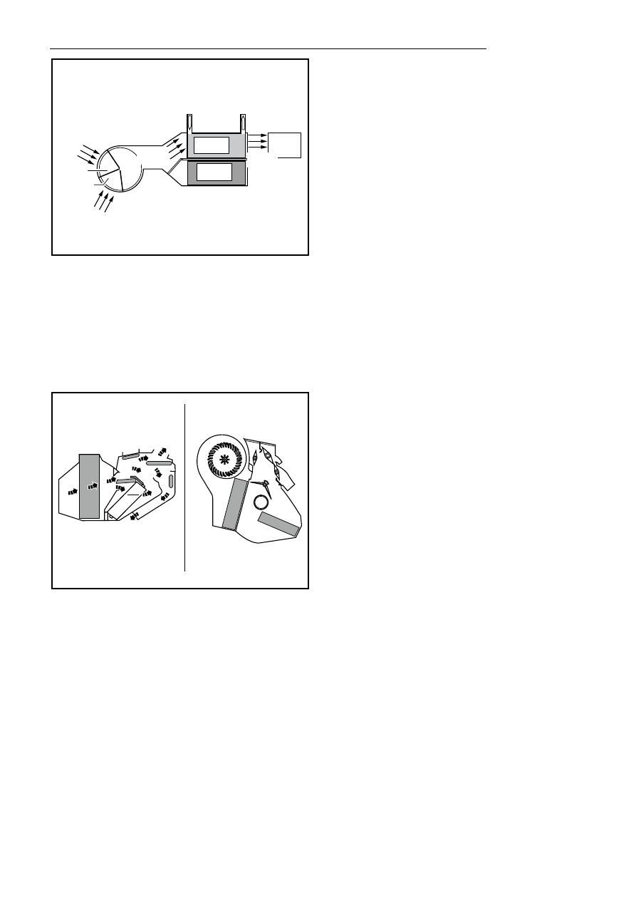
When the automatic A/C system is in the heating mode, the temperature control motor converts the temperature
control device into the heating position, so that the air entering the heater core plays the following roles in
–
Part or all air flow passes by to heating core
– Generate
heat
transmission
Any air needing not to heat will be mixed with the heated air before entering the passenger cabin to obtain the
corresponding mixed air at proper temperature.
The state of the engine coolant is the key factor that whether the heating system is working normally.
3. Venting control System work principle
NL08-2026b
Various locations on the ventilation control system can enable the mode valve to mix or induct cold air and hot air
through the air duct; and the outside air through the A/C system is transmitted to the passenger compartment via
the air duct system and the air outlet.
Automatically select the appropriate mode status in the "AUTO (automatic)" mode, and change the air supply
mode of the vehicle by using the "MODE (mode)" button. If displaying an air supply mode currently, press a
"MODE (mode)" button to select the next air supply mode.
Air flow is changed in the following mode:
–
Blowing face send wind by instrument panel
Hot-water
inlet
Warm water
outlet
Outer new
wind inlet
Inside
circulation
windinlet
Blower
Natural
wind inlet
Heating
core
Evaporation
core
Hot-wind
outlet
Wind inlet
1691