Geely Emgrand X7. Manual part - 388


  Главная      Geely     Geely Emgrand X7 - Manual


поиск по сайту            


содержание   ..   384  385  386  387  388  389 ..


Geely Emgrand X7. Manual part - 388


6.4.4 Diagnostic information and procedures 

6.4.4.1 Troubleshooting precaution 

1.    Attention should be paid when replacing each part, because it will affect performance of brake system and 

cause dangerous driving. Geely manufactured standard should be used. 

2.    When repairing brake system, it is very important to keep the parking and site clean. 

3.    If any leakage of brake fluid is found, it is necessary to disassemble it. If any abnormal situation is found, 

replace it with new components. 

4.    When dismantling the braking components, properly wrapping the brake pipeline to prevent such foreign 

matters as dust, soil, etc from entering the pipeline. 

5.    Do not damage or deform the brake line when dismantling or installing it. 

6.    Make the brake line or hose is not torsioned or bent when installing. 

7.    The flexible brake hose must be kept away from the shock absorber oil and grease. 

8.    Make sure the rigid brake pipe and flexible brake hose do not interfere with other components after they are 

installed. 

9.    Do not have the brake fluid adhere to such painted surface as the body surface. If the brake fluid is leaked to 

the painted surface, immediately remove the brake fluid. 

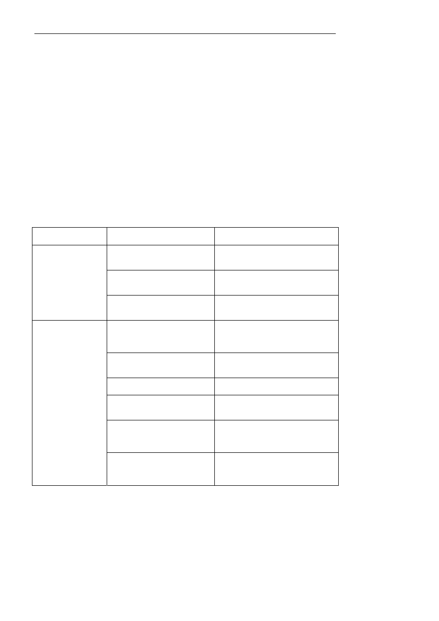
6.4.4.2 Fault Symptom Table 

Symptoms 

Suspected Parts 

Measures / Refer to 

Brake fluid level 

See 6.4.4.3 brake warning lamp keeps 
normally on. 

Brake fluid level sensor 

See 6.4.4.3 brake warning lamp keeps 
normally on. 

Brake warning lamp is 
always on 

Brake fluid level sensor harness 

See 6.4.4.3 brake warning lamp keeps 
normally on. 

1. brake lining(broken, twist, dust, 
smooth) 

See 6.2.4.1 inspection of brake pad in front 
and rear brake diagnostic information and 
procedures. 

2. brake caliper bracket fixing bolt 
(loose) 

Check brake caliper support fixing bolt 

3. brake caliper fixing bolt (loosed ) 

Check brake caliper fixing bolt 

4. brake disc (flaw) (front) 

See 6.2.4.5 brake disc surface and wear 
inspection. 

5. brake disc guide plate (loosening) 

See 6.2.4.3 inspection of brake pad guide 
plate in front and rear brake diagnostic 
information and procedures. 

The brake system has 
noise. 

6. brake caliper floating pin (wear) 

See 6.2.4.4 inspection of brake caliper 
floating pin in front and rear brake 
diagnostic information and procedures. 

1551


1. piston(fixed, stuck) 

See 6.2.4.2 inspection of brake caliper in 
front and rear brake diagnostic information 
and procedures. 

2. brake disc (with crack) 

See 6.2.4.5 brake disc surface and wear 
inspection in front and rear brake diagnostic 
information and procedures. 

3 .    Brake pad( crack .    twist or oil 
mark) 

See 6.2.4.1 inspection of brake pad in 
front and reare brake diagnostic information 
and procedures. 

Brake offset 

4 brake rigid pipe, hose (distorted, 
deformation) 

Check    brake rigid pipe and hose 

1. hydraulic brake booster system 
(vacuum leakage, fail) 

Inspect the hydraulic vacuum booster. 

The brake pedal is too 
hard. 

2.  brake rigid pipe, hose (distorted, 
deformation) 

Check    brake rigid pipe and hose 

1. brake system brake fluid leakage 

Check    brake system brake fluid leakage 

2. there is air in brake system. 

See 6.4.5.5 hydraulic brake system air 
exhausting procedures in this section 
dismantlement and installation. 

3. brake disc (with crack) 

See inspection of brake discs in front and 
reare brake diagnostic information and 
procedures. 

4. bracke lining (breakage, torsion, 
excessive wear or oil stain) 

See 6.2.4.1 inspection of brake pad in 
front and reare brake diagnostic information 
and procedures. 

The brake pedal is too 
soft and the brake is 
insufficient. 

5 brake master cylinder (internal 
leakage) 

Check  brake master pump 

1. brake pedal free stroke (shortage) 

See 6.4.5.8 replacement of brake pedal in 
this section dismantlement and installation. 

2. parking brake rod stroke (can't be 
adjusted) 

See 6.5.5.4 adjustment of parking brake 
control mechanism assembly in parking 
system dismantlement and installation. 

3 .front parking brake cable (struck) 

See 6.5.5.3 replacement of parking brake 
control mechanism assembly control cable. 

4 . left / right parking brake cable 
( stuck ) 

See 6.5.5.3 replacement of parking brake 
control mechanism assembly control cable. 

brake lag 

5 .   brake pad(clamping stagnation)

See  6.2.4.1  inspection  of  brake  pad  in 
front and reare brake diagnostic information 

1552


and procedures. 

Floating pin of brake caliper (rust) 

See 6.2.4.4  inspection of brake caliper 
floating pin. 

6. piston (fixed, jammed) 

See 6.2.4.2 inspection of brake caliper in 
front and rear brake diagnostic information 
and procedures. 

7. The vacuum booster is jammed. 

Inspect the vacuum booster. 

8. brake master pump (fault) 

Check brake master pump 


1553


6.4.4.3 Brake warning lamp is always ON 

Circuit diagram: 

NL06-1004b

1

IP01

2

IP01

9

IP02

1

CA20

2

CA20

B+

IG

IG1

IP+B

BRAKE FLUID

15A IF06

10A IF25

制动液液位
传感器

IPC

IP01

3

6

IP01

SENS GND

GND


Diagnostic Steps: 

Check brake fluid level . 

A.Check if brake fluid level is normal 


Check the harness (combination instrument    asembly power supply, ground). 


(a)    Make ignition switch turn to OFF. 

(b)   Disconnect negative cable from battery. 

(c)  Disconnect IP01 connector from combination 

instrument  

(d)   Battery negative cable connects to battery. 

(e)    Ignition switch was turned to ON (IG). 

(f)  Use multimeter to measure voltage between 

connector IP01 terminal 1 and 2 respectively with 
vehicle body groudning. 

Standard voltage:11-14V 

NL06-1014b

IP01 组合仪表线束连接器1

16

1

2

3

4

5

6

7

8

9

10

11

12

13

14

15

17

32 31 30 29 28 27 26 25 24 23 22 21 20 19 18

3

6

2

1


Fill brake fluid to MAX. 

Yes 

No 

Brake fluid 

level fluid 

IP01 combination instrument harness 

connector1


1554


содержание   ..   384  385  386  387  388  389 ..