Geely Emgrand X7. Manual part - 387


  Главная      Geely     Geely Emgrand X7 - Manual


поиск по сайту            


содержание   ..   384  385  386  387  388  ..


Geely Emgrand X7. Manual part - 387


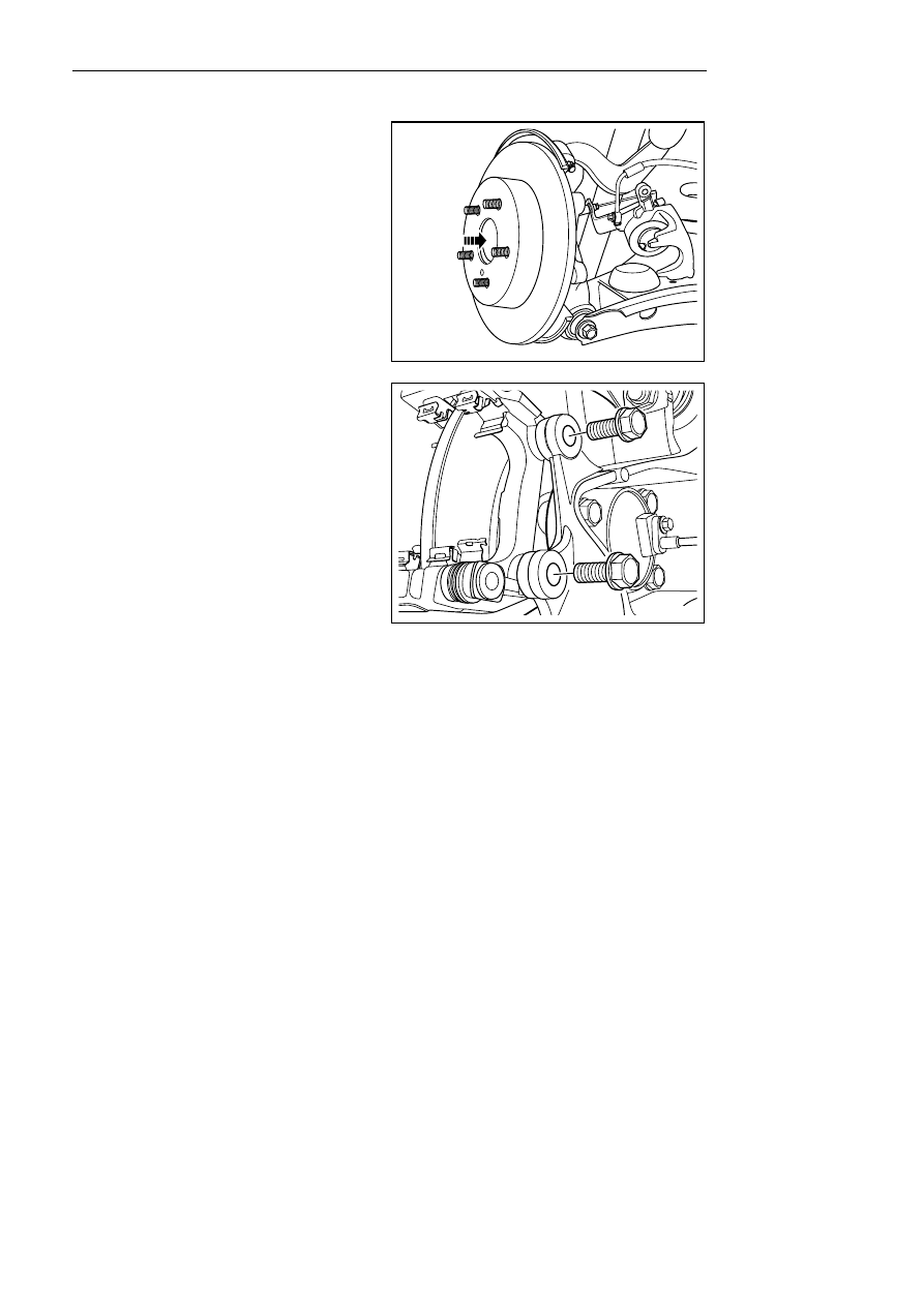
Installation procedure: 

1. Align marks of brake disc and axle wheel hub, and 

install brake disc. 


NL06-0026b


2.  Install brake caliper support and tighten bolt. 

Torque: 40Nm (Metric) 29. 6lb-ft(English system) 

3.   Install brake pad. 

4.    Install parking brake cable. 

5.    Install the rear wheels 

6.   Lower the vehicle. 

Notes: 

Similarly disassembly method of left/right rear brake 
disc. 

NL06-0027b


1547


6.4 Hydraulic Brake 

6.4.1 Specifications 

6.4.1.1 Fastener specifications 

Torque Range 

Fastener Name 

Model 

Metric (N.m) 

English system 

(lb-ft) 

Brake Master Cylinder Retaining Nut 

M8 

16 - 22 

11.8 - 16.3 

Brake hose connector nut 

M8 

16 - 22 

11.8 - 16.3 

Vacuum Booster Retaining Nut 

M8 

16 - 22 

11.8 - 19.2 

The fixing bolt of brake pedal assembly 

M8×20 

16 - 26 

11.8 - 19.2 


1548


6.4.2 Description and operation 

6.4.2.1 Description and operation 

The hydraulic brake system comprises the following parts: 

Brake pedal: receiving, amplifying and transmitting the input force of the brake system from the driver. 

Brake pedal push rod: transmitted to the vacuum booster through the amplified output force of the brake pedal. 

Vacuum booster: the input force of the brake system is increased through the brake pedal, and then transmitted to 
the vacuum booster through the brake pedal push rod, and applied to the hydraulic brake master cylinder through 
the assistance of the vacuum booster. The vacuum booster utilizes the vacuum source for assistance to reduce the 
control force of the brake pedal applied by the driver. 

Vacuum hose: used for transporting the vacuum source needed to the vacuum booster. 

Brake master cylinder fluid reservoir: the inside is equipped with brake fluid used for hydraulic brake system. 

Brake master cylinder: the mechanical input force is converted into the hydraulic output pressure which is 
distributed to two hydraulic oil paths from the master cylinder for providing oil to the diagonal wheel brake oil 
path. 

Brake hard tube and brake hose: transmit the brake fluid to flow through various parts of the hydraulic brake 
system. 

Brake wheel cylinder: converting the hydraulic input pressure into the mechanical output force. 

System operation: 

The mechanical force from the brake pedal is converted into the oil pressure via the master cylinder, which is 
conveyed to the brake cylinder through the brake hard tube and the hose after the adjustment of the hydraulic 
electronic control unit (i.e., HECU), then the oil pressure is converted into the mechanical force through the brake 
cylinder so that the brake pad compresses the brake disc to brake the vehicle. 

Brake fluid level too low warning lamp 

When detecting that the brake fluid level is too low (signal circuit is low potential), the combination instrument 
will turn on the warning lamp on low brake fluid level. 

1549


6.4.3 Component position 

6.4.3.1 Component position 

1

2

3

NL06-1003b


1.    Brake master pump fluid reservoir 

2.   Vacuum booster 

3.  Brake main pump. 


1550


содержание   ..   384  385  386  387  388  ..