Geely Emgrand X7. Manual part - 289


  Главная      Geely     Geely Emgrand X7 - Manual


поиск по сайту            


содержание   ..   284  285  286  287  288  289  290  ..


Geely Emgrand X7. Manual part - 289


3.3.6.9 Shifter replacement   

Dismantle procedure 

1.  Disconnect the battery negative cable. Refer to 2.11.8.1 battery cable disconnection/connection procedures. 

2.  Dismantle auxiliary instrument panel on the top of shifter; refer to 12.8.3.4 auxiliary instrument panel 

assembly replacement. 

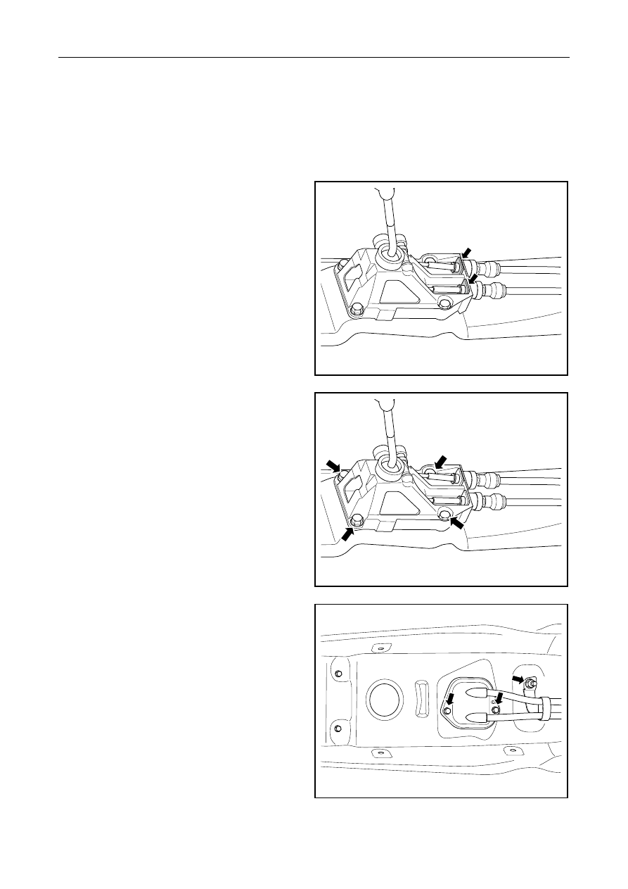
3.  Dismantle U-shaped snap plate. 

4.  Disconnect flexible shaft of gearshift and shifter. 


GC03-0012c

5.  Dismantle fixing bolts between shifter assembly 

and body. 

6.  Dismantle shifter assembly. 


GC03-0010c

7.  Dismantle retaining bolt of fixed bracket for 

flexible shaft for gear shift. 

8.  Dismantle retaining bolt of seal clip plate for 

flexible shaft for gear shift. 


GC03-0011c

1155


9.  Dismantle U-shaped snap plate. 

10.  Disconnect flexible shaft of gearshift and the 

transmission. 

11.  Dismantle flexible shaft of gear shift. 

GC03-0013c

Installation procedure: 

1.  Install flexible shaft of gear shift. 

2.  Connect flexible shaft of gearshift with the 

transmission and install lockpin. 

3.  Install U-shaped snap plate. 


GC03-0013c

4.  Install seal clip plate of flexible shaft for 

gearshift and tighten the fixing bolts. 

5.  Install throttle body bracket and tighten retaining 

bolt. 

6.  Install the outside selector assembly and tighten 

the fixing bolts. 

Torque: 16~26 N.m (Metric system)   

9.9~16.2

 lb-ft (English system) 

7.  Connect flexible shaft of gear shift with selector 

and install lock pin. 

8.  Install U-shaped snap plate. 

9.  Install subsidiary instrument desk. 

10.  Connect battery negative cable. 

GC03-0010c


1156


3.4 S170BManual transmission 

3.4.1 Specifications 

3.4.1.1 Fastener tightening specification 

Torque: 

Fastener name 

Model 

(Metric) 

(N·M) 

English 

system(ft ,lbf) 

Fixing support bolt of shift control rod 

M8×18 

20-26 

15-19 

Engine and transmission connecting bolt 

(Upper) 

M12×50 96-110  71-81 

Engine and transmission connecting bolt 

(middle) 

M10×45 53-65  39-48 

Engine and transmission connecting bolt 

(lower) 

M10×40 53-65  39-48 

Left support fixing bolt of transmission 

M10×22 

47-57 

35-42 

Left support through screw rod and nut 

M10×100 

47-57 

35-42 

Front support fixing bolt of transmission 

M10×22 

47-57 

35-42 

Through screw rod and nut of front support of 

transmission 

M10×90 47-57  35-42 

Drive gear lock bolt of speed sensor 

M8×15 

20-26 

15-19 

Rear support fixing nut of transmission 

M10 

47-57 

35-42 

Rear support through screw rod and nut of 

transmission 

M12×100 70-90  52-67 

Outer housing mounting bolt of transmission 

M8×35 

20-26 

15-19 

Mounting bolt of shift control mechanism 

M8×35 

20-26 

15-19 

End-cover connecting bolt 

M6×15 

7-11 

5-8 

Shift shaft self-lock bolt 

M18×25 

37-40 

27-30 

Lock bolt of reverse idling wheel shaft 

M8×35 

20-26 

5-19 

Fork fixing bolt 

M8×15 

20-26 

5-19 

Check hole bolt of oil level 

M18×10 

28-30 

21-22 

oil exhaust hole bolt 

M18×10 

28-30 

21-22 

1157


3.4.1.2 Manual transmission specifications 

Applications Specification 

Gear ratio 


1st speed   

3.182 

2nd speed   

1.895 

3rd speed   

1.25 

speed 0.909 

5th speed   

0.8235 

Reverse gear 

3.133 

Main reduction ratio 

4.308 

Gear oil capacity 

2.0~2.2L 

Lubrication oil 

SAE 75W/90 GL-4 

Type and model 

JLS170BⅡ 


1158


содержание   ..   284  285  286  287  288  289  290  ..