Geely Emgrand X7. Manual part - 290


  Главная      Geely     Geely Emgrand X7 - Manual


поиск по сайту            


содержание   ..  289  290  291  ..


Geely Emgrand X7. Manual part - 290


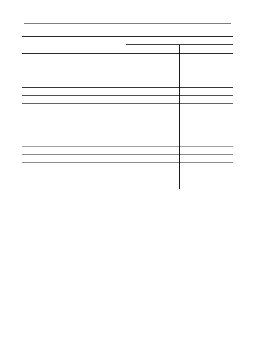
3.4.1.3 Size parameter specification 

Specification 

Dimensional parameter 

Metricmm English 

system(in×10-3)

Input shaft 3rd speed gear axial clearance 

0.1~0.35 

3.937 ~13.780 

Input shaft 5th speed gear axial clearance 

0.1~0.50 

3.937~19.685 

Input shaft 4th speed , 5th speed gear radial clearance

0.058

 2.146


Input shaft 4th speed gear axial clearance 

0.1~0.55 3.937~21.654 

Input shaft run out 

0.03

 1.181


Distance synchronous ring back and gear end-face 

0.8

 31.496


Distance between gear bushing and shift fork 

0.35

 13.780


Min.diameter under the input shaft worn condition 

33.985 and 30.985 

1337.989 and 1219.879 

Gear axial clearance of main shaft 1st speed and 2nd 

speed 

0.1~0.35 3.937~13.780 

Gear radial runout of main shaft 1st speed and 2nd 

speed 

0.056

 2.205


main bearing radial runout 

0.03

 1.181


Worn condition of main shaft:Min,diameter 

33.985 

1337.989 

Distance from shift gear cove oil(sideward) seal end 

-face to oil seal hole end-face 

2.0~2.5 78.740~98.425 

Distance from shift gear cove oil(upper side) seal end 

-face to oil seal hole end-face 

0~0.5 0~19.685 


1159


3.4.2 Description and operation 

3.4.2.1 Transmission system and operated description 

Warning: in the course of diagnosis and maintenance, it is necessary to strictly comply with the safety and 
normative operation standard in order to avoid from personal injury and vehicle damage. See Warning for 
lifting vehicle and warning for road test in warning and precaution . During maintenance of disassembling 
the transmission, a special tool for repairing the transmission must be used for prevented dust from mixing; 
therefore, not only the maintenance efficiency and quality can be improved, but also the vehicle is 
prevented from unnecessary damage. 

The transmission is manual constant mesh 5the speed all synchronizer transmission 

Control gears as shown in figure: 

1

3

5

2

4

R

FE03-2001b


Basic part included: 

z  Transmission housing 

z  Gear ring and differential assembly 

z  Shift control mechanism 

z  Input shaft 

z  Input shaft gear 

z  Main shaft   

z  Main shaft gear 

Shift control mechanism 

The shift control mechanism selects the shift fork shaft through moving the shift pin of the shift control 
mechanism up and down via the shift operation mechanism and selects the gear to be put into through moving left 
and right. Prevent out-of-gear through the self-locking bolt of the shift shaft. An interlocking pin is installed 
among the fifth reverse gear fork shaft and the first and 2nd speed    fork shaft as well as among the 5th speed 
reverse gear fork shaft and the third and fourth gear fork shaft to prevent from putting into two gears at the same 
time; thereby ensuring the normal operation of the transmission. 

1160


Forward gear 

The implementation of the forward gear is completed in combination with a group of shift sliding fork that 
controls the synchronizer with a lock ring. 

Reverse gear 

The Reverse gear is not synchronized, and a sliding idle gear is adopted; when putting into the Reverse gear, the 
sliding idle gear is engaged with the input shaft revering gear and the main shaft reversing output gear at the same 
time; the input torque is transmitted to the main shaft to output; and the steering of the main shaft is reverse to that 
of the main shaft put into the forward gear, thereby reversing the vehicle. 


1161


3.4.3 System operating principle 

3.4.3.1 System operating principle 

z  Operating principle of gearshift 

It is unable to meet of requiring the vehicle has fairly large traction and speed change in a complicated service 
condition because the variation range of the engine output torque and revolution speed is narrower. The function 
of the transmission is to change the transmission ratio of the output torque and RPM of the engine to widen the 
variation range of the torque and RPM of the driving wheel so as to adapt to frequently changing service 
conditions. 

The transmission of the vehicle is a manual five-speed two-axis transmission, including five forward gears, 
reverse gear and neutral. The shift control mechanism is controlled by the shift lever and pushes the fork shaft and 
the fork to engage the gear synchronizer to be selected and the gear synchronously; the input shaft torque and the 
speed are transmitted to the spindle and are transfer to the differential through the spindle; and the half shaft and 
the wheels are driven. 

1.  Idle working status: gearshifting control mechanism doesn't push fork shaft and shifting yoke. Synchronizer 

and gear engagement are synchronous. Reversing idle wheel doesn't arrange with input shaft reversing gear 
and main shaft output gear. main shaft has not torque and speed output.       

FE03-2002b


1162


содержание   ..  289  290  291  ..