Geely Emgrand X7. Manual part - 46


  Главная      Geely     Geely Emgrand X7 - Manual


поиск по сайту            


содержание   ..  40  41  42  43  44  45  46  47  ..


Geely Emgrand X7. Manual part - 46


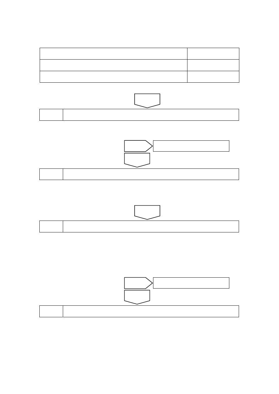
terminal No.1 and a reliable ground. Inspect whether the circuit is short to power supply. 
Otherwise, repair the faulty part. 

Test Items 

Standard Value 

EM23(3)-EM01(29) Less 

than 

Ω 

Voltage Between EM23 (3) and a Reliable Ground 

0V 

Execute next step as per normal. 


Step 7 

Inspect the ECM Power Supply Circuits. 

(a)  Inspect whether ECM power supply circuit is normal. 

(b)  Inspect whether ECM ground circuit is normal. 


Step 8 

Replace ECM 

(a)  Refer to 2.2.8.1 Replacement of Engine Control Module to Replace ECM. 

(b)  Carry out the crankshaft position sensor learning, refer to 2.2.7.11 “Crankshaft Position 

Sensor (CKP) Learning. 


Step 9 

Use fault diagnosis tester to confirm if DTC is stored again . 

(a)  Connect the fault diagnosis tester to the diagnostic interface. 

(b)  Turn ignition switch to ON position. 

(c)  Clear DTC code. 

(d)  Start and run the engine at idle speed to warm up the engine for at least 5 min. 

(e)  Read control system DTC code again to confirm that the system has no DTC code exported. 


Step 10 

Troubleshooting 

5. Maintenance 

guide 

Replace the temperature sensor of engine coolant. Refer to 2.2.8.2 Replacement of temperature 
sensor of engine coolant. 

No 

Refer to 2.2.7.3 Intermittent Fault 
Inspection for intermittent fault. 

Yes 

Next 

No 

Repair the faulty part. 

Yes 

Next 

183

2.2.7.21 DTC P0122 P0123 

1. DTC 

description: 

DTC P0122  Electronic Throttle Position Sensor #1 Circuit Low Voltage 


DTC P0123  Electronic Throttle Position Sensor 1 Circuit High Voltage or open 

TPS1 sensor sends signal through ECT harness connector EM13 terminal B to ECM through ECM 
harness connector EM01 terminal No.52. If the TPS1 sensor signal is lost, but ECM is able to 
receive the normal TPS2 sensor signal, then ECM controls the engine to enter reliability of 
determining the driver's intention decline or no high power output mode. Engine responds to the 
pedal changes slowly and engine power output will be significantly weaker, although the vehicle 
can still be able to drive in normal traffic. 

2.  Conditions For Setting DTC and The Fault Location: 

DTC Code 

DTC Detection 
Strategy 

Conditions For Setting The DTC 
(Control Strategy) 

Fault Locations 

P0122 

Hardware 
Circuit 
Malfunction 

TPS signal end short to ground or 
open, the input signal is less than 
3.5%, DTC code set. 

P0123 

Hardware 
Circuit 
Malfunction 

TPS signal end short to power supply, 
input signal is greater than 96.5%, 
DTC code set. 

1. Electronic 

Throttle Body 

2. Electronic 

Throttle Circuit 

3. ECM 

3. Circuit 

sketch 


电子节气门体

20

EM01 MR-

H

M

21

EM01 MR+

E

52

EM01 TPS1

B

70

EM01 V5REF1

D

27

EM01 TPS2

C

74

EM01 V5RTN1

A

NL02-0038c


4. Diagnostic 

Steps: 

Note: Before carrying out this diagnosis step, observe the data list on fault diagnosis tester and 
analyze the accuracy of the data, as these will help with quick diagnosis. 

Electric throttle body

Engi

ne

 co

ntr

ol mo

dul

184

Step 1 

Inspect for DTC code P0641, P0651, P0222, P0223. 

(a)  Connect fault diagnosis tester to the vehicle diagnostic interface. 

(b)  Turn ignition switch to ON position. 

(c)  Press the fault diagnosis tester power button. 

(d)  Select the following menu items: Engine/Read DTC codes. 

(e)  Read DTC codes. 

Results 

DTC Codes Shown 

To Step 

Only P0122 and P0123 

Yes 

With P0222, P0223, P0641, P0651 

No 


Step 2 

Inspect EM13 terminal B. 


(a)  Rotated ignition switch to OFF 

position . 

(b) 

Disconnect ETC harness 
connector EM13. 

(c) 

Disconnect ECM harness 
connector EM01. 

(d) Measure  resistance  between 

EM13 terminal B and a reliable 
ground. 

(e)  Measure voltage between EM13 

terminal B and a reliable ground. 

(f)  Test continuity between EM13 

terminal B and EM01 terminal 
No.52. 

电子节气门线束连接器 EM28

A

E

B

F

C

G

D

H

NL02-0029c

Results 

Test Items 

Standard Value 

EM13 (B) and a Reliable Ground 

10 kΩ or higher 

Voltage Between EM13 (B) and a Reliable Ground 

0V 

EM13 (B) and EM01 (52) Continuity 

Less than 1 Ω 

Does it conform to the standard value? 

No 

Refer to2. 12.7.46 DTC P0641 
P0651

Yes 

Electric throttle harness connectorEM28 

185


Step 3 

Inspect terminal B voltage output signal. 

(a) Connect 

ETC 

harness connector EM13. 

(b)  Connect ECM harness connector EM01. 

(c)  Measure ETC harness connector EM13 terminal B output voltage. 

Standard Value: Refer to 2.2.7.12 Electronic Throttle Body (ETC) Inspection. 

Is the output voltage value accorded with the standard value? 


Step 4 

Inspect ECM Power Supply Circuit and ground circuit. 

(a)  Refer to 2.2.7.43 DTC P0562 P0563 to inspect ECM Power Supply Circuit and ground 

circuit. 

ECM power and ground circuits normal? 


Step 5 

Replace ECM 

(a)  Refer to 2.2.8.1 Replacement of Engine Control Module to Replace ECM. 

(b)  Carry out the crankshaft position sensor learning, refer to 2.2.7.11 “Crankshaft Position 

Sensor (CKP) Learning. 


Step 6 

Use fault diagnosis tester to confirm if DTC is stored again . 

(a)  Connect the fault diagnosis tester to the diagnostic interface. 

(b)  Turn ignition switch to ON position. 

(c)  Clear DTC code. 

(d)  Start and run the engine at idle speed to warm up the engine for at least 5 min. 

(e)  Read control system DTC code again to confirm that the system has no DTC code exported. 


Step 7 

Troubleshooting 

No 

Refer to 2.2.7.3 Intermittent Fault 
Inspection for intermittent fault. 

Yes 

Next 

No 

Repair power and ground circuits fault. 

Yes 

No 

Refer to Replacement of Electrical Throttle Body 
Assembly to replace the Electrical Throttle Body (ETC). 

Yes 

No 

Refer to2. 12.7.46 DTC P0641 
P0651

Yes 

186


содержание   ..  40  41  42  43  44  45  46  47  ..