Volkswagen 4-cyl. injection engine (1.8 and 2.0 l engine, chain drive). Manual (Edition 08.2018) - page 7
 

  Index      Manuals     Volkswagen 4-cyl. injection engine (1.8 and 2.0 l engine, chain drive). Manual (Edition 08.2018). Workshop Manual (Edition 08.2018)


Search            copyright infringement  


Content      ..     5      6      7      8     ..


Volkswagen 4-cyl. injection engine (1.8 and 2.0 l engine, chain drive). Manual (Edition 08.2018) - page 7


3.2

Removing and installing camshaft

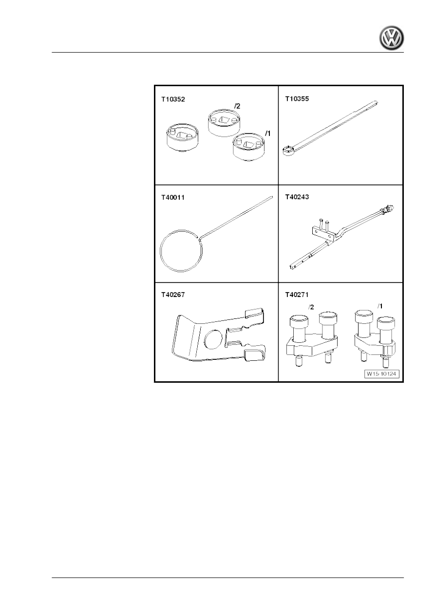
Special tools and workshop

equipment required

♦ Assembly tool - T10352-
♦ Engine codes CCZA, CCZB, CCZC, CCZD, CDAA, CDAB:

assembly tool - T10352/1-

♦ Counter-hold tool - T10355-
♦ Pin - T40011-
♦ Assembly lever - T40243-
♦ Locking tool - T40267-
♦ Camshaft clamp - T40271-

185

♦ Thrust piece - T10174-

♦ Puller - T40039-

♦ Silicone sealant - D 154 103 A1-

Note

Sealing surfaces at bottom of cylinder head cover and top of

cylinder head must not be machined.

Camshaft bearings are integrated in cylinder head and in cyl‐

inder head cover. The camshaft timing chain must be relieved

of tension before you remove the cylinder head cover.

Renew sealing cap if cylinder head cover has been detached

⇒ Item 15 (page 184)

 .

Fit cable ties in the original positions when installing.

Removing:
– Pull off engine cover panel 

⇒ page 141

 .

– Remove vacuum pump 

⇒ page 180

 .

– Remove noise insulation ⇒  General body repairs, exterior;

Rep. gr.  66 ; Noise insulation; Assembly overview - noise in‐

sulation .

– Remove right wheel housing liner ⇒  General body repairs,

exterior; Rep. gr.  66 ; Wheel housing liner; Removing and

installing wheel housing liner .

     Rep. gr.15 - Cylinder head, valve gear

– Unscrew bolts -arrows-.
– Remove air pipe (lift clips -items 1 and 2-).

– Pull off connector -1- from camshaft control valve 1 - N205- .
– Unscrew bolts -arrows- and remove inlet camshaft control

valve 1 - N205- .

– Remove upper timing chain cover 

⇒ page 91

 .

– Remove control valve using assembly tool - T10352- (engine

codes CCZA, CCZB, CDAA, CDAB: assembly tool -

T10352/1- ) in -direction of arrow-.

Caution

The control valve has a left-hand thread.

– Remove bolts -arrows- and detach bearing saddle.

187

– Turn vibration damper to “TDC” position -arrow- using coun‐

terhold - T10355- .

• Notch on vibration damper must align with arrow marking on

cover for timing chains (bottom).

• The markings -1- on the camshafts must face upwards.

– Mark positions of sprocket markings -1- on camshaft timing

chain and cylinder head -arrows- using a permanent felt tip

marker.

– Also mark alignment of camshaft timing chain -2- relative to

guide rail of camshaft timing chain using a permanent felt tip

marker.

– Remove sealing plug -arrow-.

– Unscrew bolts -arrows-.

     Rep. gr.15 - Cylinder head, valve gear

– Unscrew bolt -arrow-.

Depending on version, either of two different chain tensioners

may be installed. Version 1:
– Screw in lever - T40243- -arrows-.

Note

If it is not possible to insert the lever - T40243- , the distance

between the timing chain and the oil deflector on the lower

cover is too small. It is then necessary to remove the lower

cover.

Passat, CC 

⇒ page 93

Golf, Eos, Scirocco 

⇒ page 99

Tiguan 

⇒ page 106

– Raise locking element of chain tensioner -arrow 1-. To do this,

grind the tip of the locking pin - T40011- to a point. A screw‐

driver with a blade width of approx. 1.5 mm can also be used.

Caution

Avoid damage to chain tensioner! Proceed with great care.

– Slowly push valve lever - T40243- in -direction of arrow 2- and

hold it in that position.

– Secure chain tensioner with locking pin - T40011- .

189

Version 2:
– Screw in lever - T40243- -arrows-.

Note

If it is not possible to insert the lever - T40243- , the distance

between the timing chain and the oil deflector on the lower

cover is too small. It is then necessary to remove the lower

cover.

Passat, CC 

⇒ page 93

Golf, Eos, Scirocco 

⇒ page 99

Tiguan 

⇒ page 106

– Press together securing clip -arrow- of chain tensioner. Then,

slowly push lever - T40243- in -direction of arrow- and hold it

in that position.

– Secure chain tensioner with locking pin - T40267- .
All
– Remove lever - T40243- .

– Bolt camshaft clamp - T40271/2- to cylinder head and insert it

in direction of arrow -2- between teeth of sprocket. If necessary

turn inlet camshaft slightly in direction of arrow -1- using span‐

ner.

     Rep. gr.15 - Cylinder head, valve gear

– Bolt camshaft clamp - T40271/1- to cylinder head. Counter‐

hold camshaft clockwise -arrow- using open-end spanner.

– Remove bolt -A- and take out tensioning rail downwards. In

the process, continue to counterhold the camshaft.

– Turn exhaust camshaft clockwise -1- until camshaft clamp -

T40271/1- can be inserted into sprocket splines.

– Use screwdriver to release catch and press off top guide rail

-1- forwards. Mark position of sprockets -arrow- relative to

camshaft clamp.

– Remove camshaft timing chain from camshaft sprockets.

Caution

Risk of damaging valves, piston crowns and lower timing chain

cover.

♦ Ensure the timing chain is always under tension when

turning the crankshaft.

♦ Plates to prevent the chain falling down are attached to

the lower timing chain cover. If the crankshaft is turned

when the chain is loose, the plates may bend.

191

If the camshafts are renewed, the markings which you applied

earlier must be transferred. To do so, proceed as follows:
– Before removing camshafts, mark alignment of camshaft

sprockets relative to camshaft clamp - T40271/1- and cam‐

shaft clamp - T40271/2- -arrow-.

Note

The following measurement of distances is later used to check

whether the markings have been correctly transferred.

– Measure distance from left outer edge of web -A- to marking

-B- on inlet camshaft and record figure.

– Measure distance from marking on inlet camshaft -B- to mark‐

ing on exhaust camshaft -C- and record figure.

– Turn inlet camshaft in -direction of arrow 1- using spanner,

remove camshaft clamp - T40271/2- in -direction of arrow 2-

from between teeth of sprocket and bring camshaft into rest

position.

     Rep. gr.15 - Cylinder head, valve gear

– Turn exhaust camshaft in -direction of arrow 1- using spanner,

remove camshaft clamp - T40271/1- in -direction of arrow 2-

from between teeth of sprocket and bring camshaft into rest

position.

– Removing ignition coils with output stages 

⇒ page 562

 .

Engine codes CCZA, CCZB, CDAA, CDAB:
– Separate crankcase breather hoses -1 and 2-.
– Remove bolts -arrows- and remove crankcase breather.

Engine codes CBFA, CCTA:
– Disconnect crankcase breather hose -1-.
– Unscrew bolts -arrows-.

– Unscrew bolt -arrow- for air pipe.
– Loosen hose clip -1- and remove air pipe together with crank‐

case breather.

193

All:
– Disconnect vacuum line -1- and move line to one side.
– Detach and remove electrical connector -2- from Hall sender

- G40- .

– Undo and remove cylinder head cover bolts in the sequence

-1 … 6-.

– Remove cylinder head cover.
– Detach camshafts.
– Prevent dirt and residual sealant from entering cylinder head.
Installing camshafts
If new camshafts are to be fitted, transfer the markings which you

made on the removed camshafts to the new ones.
• Specified torques 

⇒ page 182

Note

After installing camshafts wait for approx. 30 minutes before

starting engine. The hydraulic compensation elements must

settle (otherwise valves will strike pistons).

After working on the valve gear, turn the engine carefully at

least 2 rotations to ensure that none of the valves make con‐

tact when the starter is operated.

Sealing surfaces must be free of oil and grease.

The pistons cannot be positioned at TDC.

Ensure that all roller rocker fingers are properly seated on

valve stem ends.

Note expiry date of silicone sealant.

The cover must be installed within 5 minutes after applying the

silicone sealant.

Prevent dirt and residual sealant from entering cylinder head.

– Remove sealant remaining on cylinder head with flat scraper.

WARNING

Wear protective goggles.

     Rep. gr.15 - Cylinder head, valve gear

– Remove sealant left in groove of cylinder head cover and on

sealing surfaces, e.g. using a rotating plastic brush.

– Clean sealing surfaces. They must be oil and grease free.

– Cut off nozzle on tube at front marking (∅ of nozzle approx. 2

mm).

– Oil running surfaces of both camshafts.

– Install camshafts in cylinder head. Recesses -arrows- must be

vertical to each other.

– Renew bolts for cylinder head cover.

– Apply silicone sealant - D 154 103 A1- onto clean sealing sur‐

face of cylinder head cover, as illustrated -arrows-.

♦ Thickness of sealant bead: 2 to 3 mm.

Note

The cylinder head cover must be installed within 5 minutes

after applying the silicone sealant.

The bead of sealant must not be thicker than specified, other‐

wise excess sealant can enter the sump and obstruct the

strainer in the oil intake pipe.

Check the expiry date of the sealant.

– Tighten bolts in several stages; tightening sequence

⇒ page 184

 .

195

Note

Take care to keep cylinder head cover level.

Use thrust piece - T10174- to drive in sealing cap -1- without

sealant.

Dimension -a-: 1 to 2 mm

Caution

Risk of damaging valves, piston crowns and lower timing chain

cover.

♦ Ensure the timing chain is always under tension when

turning the crankshaft.

♦ Plates to prevent the chain falling down are attached to

the lower timing chain cover. If the crankshaft is turned

when the chain is loose, the plates may bend.

– Turn vibration damper to »TDC« position -arrow- using coun‐

terhold - T10355- .

• Notch on vibration damper must align with arrow marking on

cover for timing chains (bottom).

– Turn inlet camshaft in -direction of arrow 1- until marking -3-

aligns with camshaft clamp - T40271/2- .

– Insert camshaft clamp - T40271/2- into teeth of sprocket -2-.

     Rep. gr.15 - Cylinder head, valve gear

– Turn exhaust camshaft in direction of arrow -1- until marking

-3- aligns with camshaft clamp - T40271/1- .

– Insert camshaft clamp - T40271/1- in -direction of arrow 2- be‐

tween teeth of sprocket.

Procedure for new camshafts:

– Compare distance from left outer edge of web -A- to marking

-B- with figure recorded earlier.

– Compare distance from marking on inlet camshaft -B- to mark‐

ing on exhaust camshaft -C- with figure recorded earlier.

Continued for all:

– Fit camshaft timing chain on sprockets. To do this, align mark‐

ings on chain links -arrows- with markings on sprockets -1-.

– Install upper guide rail -2-.

Note

Have a second mechanic hold the exhaust camshaft.

197

– Slowly turn exhaust camshaft in direction of arrow -1- until

camshaft clamp - T40271/1- can be withdrawn from sprocket

teeth.

– Carefully relieve load on camshaft until camshaft timing chain

lies against upper guide rail. Hold camshaft in this position.

– Continue to hold camshaft and install tensioning rail for cam‐

shaft timing chain. Tighten bolt -A-.

– Remove camshaft clamp - T40271/1- .

– Slide camshaft clamp - T40271/2- out of sprocket teeth -2-, if

necessary turning inlet camshaft slightly using spanner -1-.

– Remove camshaft clamp - T40271/2- .

     Rep. gr.15 - Cylinder head, valve gear

– Check valve timing. Markings on camshaft timing chain and

cylinder head -arrows- must align with markings on sprockets

-1-.

– Markings on camshaft timing chain and on guide rail of cam‐

shaft timing chain -2- must also align.

– Notch on vibration damper must align with marking on lower

timing chain cover -3-.

Note

If the previously marked markings are no longer visible, check

valve timing 

⇒ page 135

 .

– Fit bearing saddle carefully. Do not cant bearing saddle! Screw

in bolts -arrows- and tighten by hand.

– Depending on version, remove locking pin - T40011- or locking

tool - T40267- .

– Tighten bolts -arrows- for bearing saddle 

⇒ page 112

 .

– Screw in bolt -arrow-.
– Install control valve 

⇒ Item 6 (page 113)

 .

Note

If the markings on the camshaft timing chain and the guide rail

-2- no longer align even though the engine is at »TDC«, the drive

chain may have jumped on the crankshaft sprocket. Check valve

timing 

⇒ page 135

 If the timing is not correct, the camshaft timing

chain has to be taken off and fitted »again« 

⇒ page 114

 .

Further assembly is basically a reverse of the dismantling se‐

quence.

199

3.3

Checking axial clearance of camshafts

Special tools and workshop equipment required
♦ Universal dial gauge holder - VW 387-

♦ Dial gauge - VAS 6079-

Test sequence
– Perform measurement with retaining frame removed.
– Fit camshaft to be tested in retaining frame.
– Attach dial gauge - VAS 6079- with universal dial gauge holder

- VW 387- to cylinder head.

– Press camshaft against dial gauge by hand.
– Set dial gauge to “0”.
– Press camshaft away from dial gauge and read off value:
• Axial clearance: 0.05 to 0.17 mm

3.4

Renewing valve stem seals

⇒ “3.4.1 Removing and installing valve stem seals (cylinder head

installed)”, page 200
⇒ “3.4.2 Removing and installing valve stem seals (cylinder head

removed)”, page 205

3.4.1

Removing and installing valve stem seals (cylinder head installed)

     Rep. gr.15 - Cylinder head, valve gear

Special tools and workshop

equipment required

♦ Spark plug socket - 3122 B-
♦ Valve stem seal puller - 3364-
♦ Valve stem seal fitting tool - 3365-
♦ Adapter - T40012-
♦ Torque wrench - V.A.G 1331-
♦ Dismantling and assembling device for valve cotters - VAS

5161-

♦ Guide plate - VAS 5161/19C-
Removing valve stem oil seals
– Remove camshafts 

⇒ page 185

 .

– Mark allocation of roller rocker fingers and hydraulic compen‐

sation elements for reinstallation.

– Remove roller rocker fingers together with hydraulic compen‐

sation elements and place down on a clean surface.

– Unscrew spark plugs using spark plug socket and extension -

3122 B- .

201

Reworking guide plate
Check if recess -arrow- is present.
– If necessary, rework guide plate - VAS 5161/19C- -arrow-, until

it rests against cylinder head and guide plate -1- is free.

– Bolt guide plate - VAS 5161/19C- to cylinder head using

knurled screws - VAS 5161/12- .

Installation position:

-E- points towards intake side
-A- points towards exhaust side

– Set piston of respective cylinder to “bottom dead centre”.

– Screw adapter - T40012- into spark plug thread.
– Connect compressed air with pressure rating of at least 6 bar.
– Strike tight valve cotters with drift - VAS 5161/3- and a plastic

hammer.

For inlet side
– Screw retainer - VAS 5161/6- with guide fork - VAS 5161/5-

into centre thread of guide plate - VAS 5161/19C- .

– Insert assembly cartridge - VAS 5161/8- into guide plate - VAS

5161/19C- .

– Attach pressure fork - VAS 5161/2- to retainer - VAS 5161/6- .

     Rep. gr.15 - Cylinder head, valve gear

For exhaust side
– Screw retainer - VAS 5161/6- with guide fork - VAS 5161/5-

into outer thread of guide plate - VAS 5161/19C- .

– Press installation cartridge - VAS 5161/8- down and turn

knurled screw of installation cartridge - VAS 5161/8- to right

until tips engage in valve cotters.

– Move knurled screw back and forth slightly to press apart valve

cotters and capture them in the assembly cartridge.

– Release pressure fork - VAS 5161/2- .
– Remove installation cartridge - VAS 5161/8- .

– Pull off valve stem seals using valve stem seal puller - 3364- .

– If valve stem seal puller - 3364- cannot be used on account of

restricted space, drive out roll pin -arrow- with a drift and re‐

move impact extractor attachment.

– Place lower part of valve stem seal puller - 3364- onto valve

stem seal.

– Insert punch -1- into bore in lower part of puller.
– Place installation lever on puller and pull out valve stem seal

-arrow-.

203

Installing valve stem seals
– Place plastic sleeve -A-, enclosed with new valve stem seals

-B-, onto valve stem.

– Lightly oil sealing lip of valve stem seal.
– Push valve stem oil seal onto plastic sleeve.
– Carefully press valve stem oil seal onto valve guide using

valve stem seal fitting tool - 3365- .

– Take out plastic sleeve.
– Insert valve spring and valve spring plate.
– Install removal and installation device for valve cotters - VAS

5161- as shown.

Inlet side

Exhaust side

     Rep. gr.15 - Cylinder head, valve gear

Note

If the valve cotters have been removed from the installation

cartridge, they must first be inserted into the insertion device

- VAS 5161/18- .

Press assembly cartridge -VAS 5161/8- onto insertion device

from above and pick up valve cotters.

– Press installation cartridge - VAS 5161/8- down with pressure

fork - VAS 5161/2- , and turn installation cartridge knurled

screw back and forth whilst pulling upwards.

– Relieve pressure fork - VAS 5161/2- whilst pulling on knurled

screw.

– Remove removal and installation device - VAS 5161- .
The remaining assembly steps are basically a reverse of the dis‐

mantling procedure, when doing this note as follows:
– Install camshafts 

⇒ page 185

 .

3.4.2

Removing and installing valve stem seals (cylinder head removed)

Special tools and workshop

equipment required

205

♦ Valve stem seal puller - 3364-
♦ Valve stem seal fitting tool - 3365-
♦ Dismantling and assembling device for valve cotters - VAS

5161-

♦ Guide plate - VAS 5161/19C-
♦ Engine and gearbox support - VAS 6095-
♦ Cylinder head tensioning device - VAS 6419-
Removing valve stem oil seals
– Remove camshafts 

⇒ page 185

 .

– Mark allocation of roller rocker fingers and hydraulic compen‐

sation elements for reinstallation.

– Remove roller rocker fingers together with hydraulic compen‐

sation elements and place down on a clean surface.

– Insert cylinder head tensioning device - VAS 6419- into engine

and gearbox support - VAS 6095- .

– Tension cylinder head on cylinder head tensioning device as

shown in illustration.

– Connect cylinder head tensioning device to compressed air.
– Use lever -arrow- to slide air cushion under combustion cham‐

ber from which valve stem seal is to be removed.

– Allow compressed air to flow into air cushion until it lies against

valve disc.

Reworking guide plate
Check if recess -arrow- is present.
– If necessary, rework guide plate - VAS 5161/19C- -arrow-, until

it rests against cylinder head and guide plate -1- is free.

– Bolt guide plate - VAS 5161/19C- to cylinder head using

knurled screws - VAS 5161/12- .

Installation position:

-E- points towards intake side
-A- points towards exhaust side

– Insert drift -VAS 5161/3- into guide plate and use a plastic

hammer to knock loose the firmly seated valve cotters.

     Rep. gr.15 - Cylinder head, valve gear

For inlet side
– Screw retainer - VAS 5161/6- with guide fork - VAS 5161/5-

into centre thread of guide plate - VAS 5161/19C- .

– Insert assembly cartridge - VAS 5161/8- into guide plate - VAS

5161/19C- .

– Attach pressure fork - VAS 5161/2- to retainer - VAS 5161/6- .

For exhaust side
– Screw retainer - VAS 5161/6- with guide fork - VAS 5161/5-

into outer thread of guide plate - VAS 5161/19C- .

– Press installation cartridge - VAS 5161/8- down and turn

knurled screw of installation cartridge - VAS 5161/8- to right

until tips engage in valve cotters.

– Move knurled screw back and forth slightly to press apart valve

cotters and capture them in the assembly cartridge.

– Release pressure fork - VAS 5161/2- .
– Remove installation cartridge - VAS 5161/8- .

– Pull off valve stem seals using valve stem seal puller - 3364- .

Installing valve stem seals
– Place plastic sleeve -A-, enclosed with new valve stem seals

-B-, onto valve stem.

– Lightly oil sealing lip of valve stem seal.
– Push valve stem oil seal onto plastic sleeve.
– Carefully press valve stem oil seal onto valve guide using

valve stem seal fitting tool - 3365- .

– Remove plastic sleeve.
– Insert valve spring and valve spring plate.
– Remove removal and installation device for valve cotters -

VAS 5161- as shown.

207

Inlet side

Exhaust side

Note

If the valve cotters have been removed from the installation

cartridge, they must first be inserted into the insertion device

- VAS 5161/18- .

Press assembly cartridge -VAS 5161/8- onto insertion device

from above and pick up valve cotters.

– Press installation cartridge - VAS 5161/8- down with pressure

fork - VAS 5161/2- , and turn installation cartridge knurled

screw back and forth whilst pulling upwards.

– Relieve pressure fork - VAS 5161/2- whilst pulling on knurled

screw.

– Remove removal and installation device for valve cotters -

VAS 5161- .

Further assembly is basically a reverse of the dismantling se‐

quence. During this procedure, observe the following:
– Install camshafts 

⇒ page 185

 .

3.5

Checking valve guides

Special tools and workshop equipment required

     Rep. gr.15 - Cylinder head, valve gear

♦ Universal dial gauge bracket - VW 387-

♦ Dial gauge - VAS 6079-

Test sequence
– Insert valve in guide. Valve stem end must be flush with guide.

On account of differing stem diameters, only use inlet valve in

inlet guide and exhaust valve in exhaust guide.

– Determine rock.
Wear limit

Inlet valve guide

Exhaust valve guide

0.80 mm

0.80 mm

Note

If the wear limit is exceeded, repeat the measurement with

new valves. If the wear limit is exceeded again, renew the cyl‐

inder head.

If the valve is to be renewed as part of a repair, use a new

valve for the calculation.

209

17 – Lubrication

1

Sump and oil pump

Note

Finding metal shavings or a large quantity of small metal par‐

ticles during engine repair could indicate that the crankshaft

bearings or conrod bearings are damaged. To prevent this

from causing further damage, perform the following repairs:

Thoroughly clean oil channels.

Renew oil spray jets.

Renew engine oil cooler.

Renewing oil filter.

The oil level must be at or below the max. mark - danger of

damage to catalytic converter!

Assembly overview - sump, oil pump 

⇒ page 210

 .

Removing and installing coarse oil separator 

⇒ page 213

 .

Removing and installing lower part of sump 

⇒ page 213

 .

Removing and installing oil pump 

⇒ page 216

 .

Removing and installing sump upper part 

⇒ page 218

 .

Removing and installing oil pressure control valve - N428- (engine

codes CCZA, CCZB, CCZC, CCZD, CDAA, CDAB)

⇒ page 222

 .

1.1

Assembly overview - sump, oil pump

     Rep. gr.17 - Lubrication

1 - Oil level and oil temperature

sender - G266-

❑ Not in the case of engine

codes CBFA, CCTA,

CCTB

2 - Seal

❑ Renew

3 - Bolt

❑ Renew
❑ Tightening sequence

⇒ page 212

4 - Lower part of sump

❑ Removing and installing

⇒ page 213

5 - Bolt

❑ 9 Nm

6 - Baffle plate

❑ If the upper part of the

sump is renewed, the

baffle plate must also be

renewed.

7 - Securing bolts for sump

❑ Specified torque:

M6 = 9 Nm

M8 = 20 Nm

8 - Oil pump

❑ Removing and installing

⇒ page 216

9 - Centring sleeve
10 - Chain tensioner
11 - Bolt

❑ 9 Nm

12 - Bolt

❑ Only engine codes CCZA, CCZB, CCZC, CCZD, CDAA, CDAB
❑ 9 Nm

13 - Valve for oil pressure control - N428-

❑ Only engine codes CCZA, CCZB, CCZC, CCZD, CDAA, CDAB
❑ Removing and installing 

⇒ page 222

14 - O-ring

❑ Only engine codes CCZA, CCZB, CCZC, CCZD, CDAA, CDAB
❑ Renew

15 - Drive chain for oil pump

❑ Mark direction of rotation before removing.

16 - Seal

❑ Renew

17 - Coarse oil separator

❑ Removing and installing 

⇒ page 213

211

18 - Bolt

❑ Tightening sequence 

⇒ page 213

19 - Upper part of sump

❑ Removing and installing 

⇒ page 218

20 - Bolt

❑ 9 Nm

21 - Bolt

❑ Renew
❑ Tightening sequence 

⇒ page 212

22 - Oil intake tube

❑ Clean strainer if soiled

23 - O-ring

❑ Renew

24 - O-ring

❑ Renew

25 - O-ring

❑ Renew

26 - Non-return valve
27 - Oil drain plug

❑ Renew
❑ 30 Nm

28 - Nut

❑ 9 Nm

Tightening sequence for sump (bottom section)
– Tighten bolts in sequence -1 to 20- in 3 stages as follows:
1 - Tighten bolts by hand.
2 - Tighten bolts to 8 Nm.
3 - Turn bolts 45° further.

Tightening sequence for sump (top section)
– Tighten bolts in sequence -1 to 14- in 3 stages as follows:
1 - Tighten bolts by hand.
2 - Tighten bolts to 15 Nm.
3 - Turn bolts 90° further.

     Rep. gr.17 - Lubrication

Tightening sequence for coarse oil separator
– Tighten bolts in the sequence -1 … 9- to 9 Nm.

1.2

Removing and installing coarse oil sep‐

arator

Removing
– Remove noise insulation ⇒  General body repairs, exterior;

Rep. gr.  50 ; Noise insulation .

– Unscrew bolts -1 … 9- and remove coarse oil separator.

Caution

Danger of soiling lubrication system.

♦ Close opening with clean cloth.

Installing

Note

Renew gaskets and seals.

Secure all hose connections with the correct type of hose clips

(same as original equipment) ⇒  EKTA (Electronic parts cata‐

logue) .

Installation is basically carried out in the reverse sequence; note

the following when doing this:

– Tighten bolts in the sequence -1 … 9- to 9 Nm.

1.3

Removing and installing lower part of

sump

Special tools and workshop equipment required

213

♦ Used oil collector and extractor - V.A.G 1782-

♦ Hand drill with plastic brush
♦ Scraper
♦ Commercially available scraper
♦ Safety glasses
♦ Silicone sealant ⇒  Electronic parts catalogue (ETKA)
Removing
– Remove noise insulation ⇒  General body repairs, exterior;

Rep. gr.  50 ; Noise insulation .

– If fitted, disconnect electrical connector -1- for oil level and oil

temperature sender - G266- .

– Drain engine oil.

Note

Please observe disposal instructions!

     Rep. gr.17 - Lubrication

– Remove bolts -1 to 20-.
– Carefully detach lower part of sump from adhesive bond using

a commercially available scraper.

– Remove sump. If necessary, loosen using light blows with a

rubber-headed hammer.

Installing
• Specified torques 

⇒ page 210

Note

Note expiry date of silicone sealant.

The sump must be installed within 5 minutes of applying sili‐

cone sealing compound.

– Remove residual sealant from upper part of sump using a flat

scraper.

WARNING

Risk of eye injury.

♦ Wear safety goggles.

– Remove sealant residue from sump (bottom section) using a

rotating plastic brush, for example.

– Clean sealing surfaces. They must be oil and grease free.

– Cut off nozzle on tube at front marking (∅ of nozzle approx. 3

mm).

215

– Apply the bead of silicone sealant to the clean sealing surface

of the sump (bottom section), as illustrated.

Note

The sump must be installed within 5 minutes after applying the

silicone sealant.

The bead of sealant must not be thicker than specified, other‐

wise excess sealant can enter the sump and obstruct the

strainer in the oil intake pipe.

♦ Thickness of sealant bead: 2 to 3 mm.

– Fit bottom part of sump immediately and tighten bolts

-1 to 20- in 3 stages as follows:

1 - Tighten bolts by hand.
2 - Tighten bolts to 8 Nm.
3 - Turn bolts 45° further.

Note

Let sealing compound dry for approx. 30 minutes after installing

oil sump. Only then fill with engine oil.

– Replenish engine oil; oil capacities 

⇒ page 224

 .

Further assembly is basically a reverse of the dismantling se‐

quence.

1.4

Removing and installing oil pump

Special tools and workshop equipment required
♦ Assembly tool - T10118-

     Rep. gr.17 - Lubrication


Content      ..     5      6      7      8     ..