Volkswagen 4-cyl. injection engine (1.8 and 2.0 l engine, chain drive). Manual (Edition 08.2018) - page 6
 

  Index      Manuals     Volkswagen 4-cyl. injection engine (1.8 and 2.0 l engine, chain drive). Manual (Edition 08.2018). Workshop Manual (Edition 08.2018)


Search            copyright infringement  


Content      ..     4      5      6      7     ..


Volkswagen 4-cyl. injection engine (1.8 and 2.0 l engine, chain drive). Manual (Edition 08.2018) - page 6


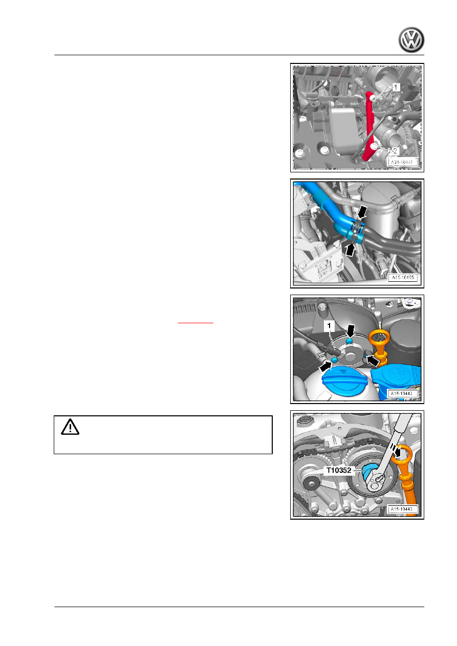
– Remove intake manifold support (remove securing nut -1- and

bolt -2-).

– Removing oil filter

– Disconnect coolant hoses -arrows- and move clear.

– Unscrew bolts -arrows- and remove inlet camshaft control

valve 1 - N205- .

– Remove timing chain cover (top) 

⇒ page 91

 .

Caution

The control valve has a left-hand thread.

– Remove control valve using assembly tool - T10352- (engine

codes CCZA, CCZB, CDAA, CDAB: assembly tool -

T10352/1- ) in -direction of arrow-.

153

– Remove bolts -arrows- and detach bearing saddle.

– Turn vibration damper to “TDC” position -arrow- using coun‐

terhold - T10355- .

• Notch on vibration damper must align with arrow marking on

cover for timing chains (bottom).

• The markings -1- on the camshafts must face upwards.

– Mark positions of sprocket markings -1- on camshaft timing

chain and cylinder head -arrows- using a permanent felt tip

marker.

– Also mark alignment of camshaft timing chain -2- relative to

guide rail of camshaft timing chain using a permanent felt tip

marker.

– Remove sealing plug -arrow-.

     Rep. gr.15 - Cylinder head, valve gear

– Unscrew bolts -arrows-.

– Unscrew bolt -arrow-.

Depending on version, either of two different chain tensioners

may be installed. Version 1:
– Screw in lever - T40243- -arrows-.

Note

If it is not possible to insert the lever - T40243- , the distance

between the timing chain and the oil deflector on the lower

cover is too small. It is then necessary to remove the lower

cover.

Passat, CC 

⇒ page 93

Golf, Eos, Scirocco 

⇒ page 99

Tiguan 

⇒ page 106

– Raise locking element of chain tensioner -arrow 1-. To do this,

grind the tip of the locking pin - T40011- to a point. A screw‐

driver with a blade width of approx. 1.5 mm can also be used.

Caution

Avoid damage to chain tensioner! Proceed with great care.

– Slowly push valve lever - T40243- in -direction of arrow 2- and

hold it in that position.

155

– Secure chain tensioner with locking pin - T40011- .

Version 2:
– Screw in lever - T40243- -arrows-.

Note

If it is not possible to insert the lever - T40243- , the distance

between the timing chain and the oil deflector on the lower

cover is too small. It is then necessary to remove the lower

cover.

Passat, CC 

⇒ page 93

Golf, Eos, Scirocco 

⇒ page 99

Tiguan 

⇒ page 106

– Press together securing clip -arrow- of chain tensioner. Then,

slowly push lever - T40243- in -direction of arrow- and hold it

in that position.

– Secure chain tensioner with locking pin - T40267- .
Continued for all:
– Remove lever - T40243- .

     Rep. gr.15 - Cylinder head, valve gear

– Bolt camshaft clamp - T40271/2- to cylinder head and insert it

in direction of arrow -2- between teeth of sprocket. If necessary

turn inlet camshaft in direction of arrow -1- using spanner.

– Bolt camshaft clamp - T40271/1- to cylinder head. Counter‐

hold camshaft clockwise -arrow- using open-end spanner.

– Remove bolt -A- and take out tensioning rail downwards. In

the process, continue to counterhold the camshaft.

– Turn exhaust camshaft clockwise -1- until camshaft clamp -

T40271/1- can be inserted into sprocket splines -2-.

157

– Use screwdriver to release catch and press off top guide rail

-1- forwards. Mark position of sprockets -arrow- relative to

camshaft clamp.

– Remove camshaft timing chain from camshaft sprockets.

Caution

Avoid damage to valves and piston crowns.

♦ Do not turn the crankshaft after the camshaft timing chain

has been removed from the cylinder head.

– If a cylinder head cover without sealing plugs for the cylinder

head bolts -5- is installed, remove the camshafts

⇒ page 185

 .

– If a cylinder head cover with sealing plugs for all cylinder head

bolts is installed, turn sealing plugs -arrows- anti-clockwise in

direction of -arrow- by 90° and remove.

– Unscrew ball head -1 … 2-.
– Remove filler cap.

Multi-point socket head bolt with shoulder:
– Remove camshafts 

⇒ page 185

 .

– Unscrew bolts -arrows-.
– Unscrew and remove cylinder head bolts in the sequence

-1 to 10-.

     Rep. gr.15 - Cylinder head, valve gear

Polydrive bolts:
– Unscrew bolts -arrows-.
– Unscrew cylinder head bolts using polydrive bit and socket -

T10070- in sequence -1 to 5-.

Note

Make sure all hoses/pipes and wiring are removed.

Ensure tensioning rail and guide rail are not damaged when

lifting off cylinder head.

– Remove cylinder head.
– Place cylinder head onto soft surface (foam plastic).
Install cylinder head 

⇒ page 162

 .

If the camshafts are renewed, the markings which you applied

earlier must be transferred. To do so, proceed as follows:
– Mark alignment of camshaft sprockets relative to camshaft

clamp - T40271/1- and camshaft clamp - T40271/2- on re‐

moved cylinder head -arrow-.

Note

The following measurement of distances is later used to check

whether the markings have been correctly transferred.

– Measure distance from left outer edge of web -A- to marking

-B- on inlet camshaft and record figure.

– Measure distance from marking on inlet camshaft -B- to mark‐

ing on exhaust camshaft -C- and record figure.

159

– Turn inlet camshaft in direction of arrow -1- using spanner,

slide camshaft clamp - T40271/2- from between teeth of

sprocket -2-and move camshaft into rest position.

– Remove camshaft clamp - T40271/2- .

– Turn exhaust camshaft in direction of arrow -1- using spanner,

slide camshaft clamp - T40271/1- from between teeth of

sprocket -2-and move camshaft into rest position.

– Remove camshaft clamp - T40271/1- .

Now complete cylinder head which is to be installed and transfer

markings applied when removing.

     Rep. gr.15 - Cylinder head, valve gear

– Bolt camshaft clamp - T40271/2- to cylinder head to be instal‐

led.

– Turn inlet camshaft in direction of arrow -1- until marking -3-

aligns with camshaft clamp - T40271/2- .

– Insert camshaft clamp - T40271/2- into teeth of sprocket -2-.

– Compare distance from left outer edge of web -A- to marking

-B- with figure recorded earlier.

– Bolt camshaft clamp - T40271/1- to cylinder head.
– Turn exhaust camshaft in direction of arrow -1- until marking

-3- aligns with camshaft clamp - T40271/1- .

– Insert camshaft clamp - T40271/1- into teeth of sprocket -2-.

161

– Compare distance from marking on inlet camshaft -B- to mark‐

ing on exhaust camshaft -C- with figure recorded earlier.

Installing cylinder head:
• Specified torques 

⇒ page 137

 .

Caution

Avoid damage to sealing surfaces.

♦ Carefully remove sealant residue from cylinder head and

cylinder block.

♦ Ensure that no long scores or scratches are made on the

surfaces.

Avoid damage to cylinder block.

♦ No oil or coolant must be allowed to remain in the blind

holes for the cylinder head bolts in the cylinder block.

Ensure that cylinder head gasket seals properly:

♦ Carefully remove remains of emery and abrasives.
♦ Do not remove new cylinder head gasket from packaging

until it is ready to be fitted.

♦ Handle the cylinder head gasket very carefully to prevent

damage to the silicone coating or the indented area of the

gasket.

Avoid damage to open valves.

♦ When installing an exchange cylinder head, the plastic

protectors fitted to protect the open valves should not be

removed until the cylinder head is ready to be fitted.

Avoid damage to valves and piston crowns after working on

valve gear.

♦ Turn the engine carefully at least 2 rotations to ensure that

none of the valves make contact when the starter is op‐

erated.

Note

Renew bolts which must be tightened further to a torque angle.

Renew self-locking nuts as well as gaskets, seals and O-rings.

When installing a exchange cylinder head, the contact surfa‐

ces between hydraulic compensation elements, roller rocker

fingers and cams must be oiled before installing the cam‐

shafts.

Hose connections and air duct pipes must be free of oil and

grease before assembly.

Secure all hose connections with the same type of hose clips

as original equipment ⇒  Electronic parts catalogue .

In order to be in a position to securely attach the charge air

hoses on their connections, the worm screws of the used hose

clips have to the sprayed with penetrating spray before instal‐

ling.

     Rep. gr.15 - Cylinder head, valve gear

– Position cylinder head gasket.
♦ Note centring pins in cylinder block -arrows-.
♦ Check installation position of cylinder head gasket. Charac‐

teristic: the part number should be legible from the inlet side.

Caution

When  turning  the  crankshaft,  pull  the  timing  chain  upwards

until taut so that it does not become jammed.

– If crankshaft has since been turned, position cylinder number

1 piston to TDC and then turn crankshaft back slightly.

– Fit cylinder head.
– Insert cylinder head bolts, and tighten them by hand.
– Tighten cylinder head:

Tightening sequence

⇒ Fig. ““Cylinder head - tightening sequence, camshaft instal‐

led”“ , page 140

Tightening sequence

⇒ Fig. ““Cylinder head - tightening sequence, camshaft re‐

moved”“ , page 140

– Install camshafts if removed 

⇒ page 185

 .

Caution

When  turning  the  crankshaft,  pull  the  timing  chain  upwards

until taut so that it does not become jammed.

– Turn vibration damper to “TDC” position -arrow- using coun‐

terhold - T10355- .

• Notch on vibration damper must align with arrow marking on

cover for timing chains (bottom).

– Fit camshaft timing chain on sprockets. To do this, align mark‐

ings on chain links -arrows- with markings on sprockets -1-.

– Install upper guide rail -2-.

Note

Have a second mechanic hold the exhaust camshaft.

163

– Slowly turn exhaust camshaft in direction of arrow -1- until

camshaft clamp - T40271/1- can be withdrawn from sprocket

teeth -2-.

– Carefully relieve load on camshaft until camshaft timing chain

lies against upper guide rail. Hold camshaft in this position.

– Continue to hold camshaft and install tensioning rail for cam‐

shaft timing chain. Tighten bolt -A-.

– Remove camshaft clamp - T40271/1- .

– Slide camshaft clamp - T40271/2- out of sprocket teeth -2-, if

necessary turning inlet camshaft slightly using spanner -1-.

– Remove camshaft clamp - T40271/2- .

     Rep. gr.15 - Cylinder head, valve gear

– Check markings. Markings on camshaft timing chain and cyl‐

inder head -arrows- must align with markings on sprockets

-1-.

– Markings on camshaft timing chain and on guide rail of cam‐

shaft timing chain -2- must also align.

– Notch on vibration damper must align with marking on lower

timing chain cover -3-.

Note

If the previously marked markings are no longer visible, check

valve timing 

⇒ page 135

 .

– Fit bearing saddle uniformly. Do not cant bearing saddle!

Screw in bolts -arrows- and tighten by hand.

– Tighten bolts -arrows- for bearing saddle 

⇒ page 112

 .

– Depending on version, remove locking pin - T40011- or locking

tool - T40267- .

– Screw in bolt -arrow-.
– Install control valve 

⇒ Item 6 (page 113)

 .

Now continue installing in reverse order of removal, observing the

following:
– Change engine oil.
– Add coolant 

⇒ page 241

 .

2.4.2

Removing and installing cylinder head and camshaft timing chain

165

Special tools and workshop

equipment required

♦ Assembly tool - T10352-
♦ Engine codes CCZA, CCZB, CCZC, CCZD, CDAA, CDAB:

assembly tool - T10352/1-

♦ Counter-hold tool - T10355-
♦ Pin - T40011-
♦ Assembly lever - T40243-
♦ Locking tool - T40267-
♦ Camshaft clamp - T40271-

     Rep. gr.15 - Cylinder head, valve gear

♦ Torque wrench - V.A.G 1331-
♦ Torque wrench - V.A.G 1332-
♦ Workshop hoist - VAS 6100-
♦ Engine plug set - VAS 6122-
♦ Drip tray for workshop hoist - VAS 6208-
♦ Polydrive cylinder head bolts: Special wrench, long reach -

T10070-

♦ Cylinder head bolts with multi-point socket: Multi-point socket

12 mm

167

♦ Lifting tackle - 2024 A-

♦ Puller - T40039-

Removing:

Note

Before the cylinder head is removed, the engine support and

engine mounting must be reinstalled temporarily, because the

eyes of the support bracket are secured to the cylinder head.

Fit the cable ties in the original position when installing.

Seal open channels of intake and exhaust system with suitable

plugs from engine bung set - VAS 6122- .

– Pull off engine cover panel 

⇒ page 141

 .

– Remove air filter housing 

⇒ page 467

 .

     Rep. gr.15 - Cylinder head, valve gear

– Release hose clip -2-.
– Unscrew bolt -4-.
– Disconnect electrical connector -arrow- and move electrical

wires clear.

WARNING

Danger of scalding by steam and hot coolant.
On a warm engine, the cooling system is under high pressure.
Cover filler cap on expansion tank with a cloth and open care‐

fully to release pressure.

– Open filler cap on expansion tank.
– Remove front exhaust pipe with catalytic converter:

Passat, CC 

⇒ page 526

Golf, Eos, Scirocco 

⇒ page 542

Tiguan 

⇒ page 552

– Remove front right wheel.
– Remove noise insulation ⇒  General body repairs, exterior;

Rep. gr.  50 ; Noise insulation .

– Remove right wheel housing liner ⇒  General body repairs,

exterior; Rep. gr.  66 ; Wheel housing liner .

– Drain coolant 

⇒ page 241

 .

– Remove charge air hose -A-.

– Remove bolt -1- and take out air pipe downwards.

169

– Unscrew bolts -arrows-.
– Remove air pipe (lift clips -items 1 and 2-).

– Separate electrical wiring connections -1 and 2- and place

electrical wiring to one side -arrows-.

Vehicles with auxiliary heater:
– Unscrew bolts -1 and 2- and move coolant pipes to the left.
Vehicles with all-wheel drive:
– Remove right drive shaft ⇒  Running gear, axles, steering;

Rep. gr.  40 ; Removing and installing drive shafts .

All vehicles:
– Remove bolts -1 and 2- and detach support for turbocharger.

     Rep. gr.15 - Cylinder head, valve gear

– Remove banjo bolt -2- and move coolant pipe clear to one

side.

Vehicles with front-wheel drive:
– Remove bolts -1- on oil return line.
Vehicles with all-wheel drive:
– Remove bolts of oil return line at crankcase.
All vehicles:
– Remove bolt -3- on oil supply line.

– Pull connector -1- off camshaft control valve 1 - N205- .

– Detach connectors from ignition coils and place wiring harness

to one side.

– Remove ignition coils using puller - T40039- .

Engine codes BZB, CAWA, CAWB, CGYA, CDAA:
– Unscrew bolt -arrow- for air pipe.
– Remove air pipe, loosening hose clip -1- to do so.
– Press release tabs -2-, and pull crankcase breather off air

hose.

171

– Disconnect crankcase breather hose -1-.
– Remove bolts -arrows- and remove crankcase breather.

Engine codes CBFA, CCTA, CCTB:
– Disconnect crankcase breather hose -1-.
– Unscrew bolts -arrows-.

– Unscrew bolt -arrow- for air pipe.
– Loosen hose clip -1- and remove air pipe together with crank‐

case breather.

All:

WARNING

The fuel line is under pressure.
Fuel poses danger of injury to eyes and skin.
Wear protective goggles and protective clothing to avoid injury

and contact with the skin. Wrap a cloth around the connection

before loosening hose connections. Then reduce pressure by

carefully opening the connection.

– Detach lines -1 to 3- from the fuel transfer point.

1) Breather hose
2) Vacuum line (only CBFA, CCTA, CCTB)
3) Fuel supply line

     Rep. gr.15 - Cylinder head, valve gear

– Disconnect coolant line to coolant expansion tank -arrow-.

– Remove coolant hoses -arrows- from coolant pipe.
– Unbolt earth cable -3- and loosen bolt -4-.

– Pull off vacuum hoses -arrows-.

– Unscrew bolts -1…3- and remove heat shield together with

coolant pipe.

– Unscrew oil supply line -4- from turbocharger.

173

Note

Unscrew bolt -2- from heat shield using a 6 mm hex key -A-. The

hexagon faces must be at least 5 cm long -B-. A socket which

tapers to 6 mm at the tip is too thick.

– Pull electrical connector -2- from fuel pressure regulating valve

- N276- .

Engine code CBFA:
– Pull connector -A- and hose -B- from secondary air inlet valve

- N112- .

– Loosen coolant pipe by unscrewing bolts -arrows-.

     Rep. gr.15 - Cylinder head, valve gear

All:
– Pull coolant hose from union on side of cylinder head.
– Separate electrical connectors -1 to 4-.
– Expose electric cable -5-.
– Pull off vacuum line -6- leading to activated charcoal filter.

Golf, Scirocco:
– Pull off breather line -1-, release activated charcoal filter -A-

and remove upwards -B-.

All:
– Disconnect electrical connectors -1- and detach connectors

from retainer.

– Separate electrical connectors -2 to 4-.

– Unscrew bolts -arrows- and detach coolant pipes from intake

manifold.

175

– Remove intake manifold support (remove securing nut -1- and

bolt -2-).

– Removing oil filter

– Disconnect coolant hoses -arrows- and move clear.
– Remove camshaft timing chain 

⇒ page 114

 .

– Reinstall engine support and engine mounting, and tighten

bolts by hand.

– Detach spindles of support bracket - 10 - 222 A- .

– If a cylinder head cover without sealing plugs for the cylinder

head bolts -5- is installed, remove the camshafts

⇒ page 185

 .

– If a cylinder head cover with sealing plugs for all cylinder head

bolts is installed, turn sealing plugs -arrows- anti-clockwise in

direction of -arrow- by 90° and remove.

– Unscrew ball head -1 … 2-.
– Remove filler cap.

     Rep. gr.15 - Cylinder head, valve gear

Multi-point socket head bolt with shoulder:
– Remove camshafts 

⇒ page 185

 .

– Unscrew bolts -arrows-.
– Unscrew and remove cylinder head bolts in the sequence

-1 to 10-.

Polydrive bolts:
– Unscrew bolts -arrows-.
– Unscrew cylinder head bolts using polydrive bit and socket -

T10070- in sequence -1 to 5-.

Note

Make sure all hoses/pipes and wiring are removed.

– Remove cylinder head.
– Place cylinder head onto soft surface (foam plastic).
Installing cylinder head:
• Specified torques 

⇒ page 137

 .

Note

Replace bolts that are tightened with specified tightening an‐

gle.

Renew gaskets, oil seals and self-locking nuts.

Hose connections and air duct pipes must be free of oil and

grease before assembly.

Secure all hose connections with the correct type of hose clips

(same as original equipment) ⇒  Electronic parts catalogue .

Spray the worm screws of the used hose clips with penetrating

spray before installing.

– Do not remove new cylinder head gasket from packaging until

it is ready to be fitted. The silicone coating and the indented

area of the cylinder head gasket must not be damaged.

– Carefully remove sealant residue from cylinder head and cyl‐

inder block. Ensure that no long scores or scratches are made

on the surfaces, while doing so. Carefully remove remains of

emery and abrasives.

– Clean blind holes for cylinder head bolts. Blow out with com‐

pressed air if necessary.

177

– Position cylinder head gasket.
♦ Note centring pins in cylinder block -arrows-.
♦ Check installation position of cylinder head gasket. Charac‐

teristic: the part number should be legible from the inlet side.

– If crankshaft has since been turned, position cylinder number

1 piston to TDC and then turn crankshaft back slightly.

– Fit cylinder head.
– Insert cylinder head bolts, and tighten them by hand.
– Tighten cylinder head:

Tightening sequence

⇒ Fig. ““Cylinder head - tightening sequence, camshaft instal‐

led”“ , page 140

Tightening sequence

⇒ Fig. ““Cylinder head - tightening sequence, camshaft re‐

moved”“ , page 140

– Using support bracket - 10 - 222 A- , support engine in instal‐

lation position again.

– Removing engine mounting and engine support.
– Install camshafts if removed 

⇒ page 185

 .

– Install drive chain for balance shaft and camshaft timing chain

⇒ page 121

 .

The remaining assembly steps are basically a reverse of the dis‐

mantling procedure, when doing this note as follows:
– Change engine oil ⇒ Maintenance ; Booklet  ; Engine oil:

Draining; Renewing oil filter and replenishing engine oil .

– Fill with new coolant 

⇒ page 241

 .

2.5

Checking compression

     Rep. gr.15 - Cylinder head, valve gear

Special tools and workshop

equipment required

♦ Spark plug socket - 3122 B-
♦ Puller - T40039-
♦ Torque wrench - V.A.G 1331-
♦ Compression tester - V.A.G 1763-
♦ Adapter - V.A.G 1381/5A-
♦ Adapter - V.A.G 1381/1-
Test sequence

Note

Observe all relevant safety precautions 

⇒ page 561

 .

Engine oil temperature min. 30 °C

Battery voltage at least 12.7 V

Proceed as follows:
– Pull off engine cover panel 

⇒ page 141

 .

– Removing ignition coils with output stages 

⇒ page 562

 .

179

– Unscrew spark plugs using spark plug socket - 3122 B- .
– Check compression using compression tester - V.A.G 1763- ,

adapter - V.A.G 1381/1- and adapter - V.A.G 1381/5A- .

Note

Using compression tester: ⇒  Operating instructions .

– Start engine until tester shows no further pressure increase.
Compression pressures:

New bar pressure Wear limit bar pres‐

sure

Difference between

cylinders bar pres‐

sure

11.0 … 14.0

7.0

max. 3.0

– Install spark plugs, specified torque 

⇒ page 562

 .

– Install ignition coils with output stages 

⇒ page 562

 .

Note

Faults will have been stored in the memory because connectors

have been disconnected. Read and, if necessary, clear the event

memory after the test.

– Read event memory of engine control unit ⇒  vehicle diagnos‐

tic tester .

2.6

Removing and installing vacuum pump

Removing:
Proceed as follows:
– Remove engine cover panel 

⇒ page 141

 .

– Remove air filter 

⇒ page 467

 .

– Remove high-pressure pump with »roller tappet«

⇒ page 491

 .

– Unbolt earth cable -3- and remove bolt -4-.

     Rep. gr.15 - Cylinder head, valve gear

– Remove vacuum hose -1- from vacuum pump.

– Unscrew bolts -arrows- and remove vacuum pump.

Note

Dismantling of the vacuum pump is not permitted.

Installing:
• Specified torques 

⇒ page 137

Perform assembly in reverse order of removal, observing the fol‐

lowing:
– Clean sealing surfaces.
– Position gasket on vacuum pump, insert 2 bolts and then po‐

sition on cylinder head.

181

3

Valve gear

Note

Cylinder head and cylinder head cover must be renewed to‐

gether.

After installing camshafts wait for approx. 30 minutes before

starting engine. The hydraulic compensation elements must

settle (otherwise valves will strike pistons).

After working on the valve gear, turn the engine carefully at

least 2 rotations to ensure that none of the valves make con‐

tact when the starter is operated.

Always renew gaskets and seals.

Assembly overview - valve gear 

⇒ page 182

 .

Removing and installing camshafts 

⇒ page 185

 .

Checking axial clearance of camshafts 

⇒ page 200

 .

Renewing valve stem seals 

⇒ page 200

 .

Checking valve guides 

⇒ page 208

 .

3.1

Assembly overview - valve gear

     Rep. gr.15 - Cylinder head, valve gear

1 - Outlet valve

❑ Do not rework. Only lap‐

ping in is permitted.

❑ Valve dimensions

⇒ page 184

❑ Checking valve guides

⇒ page 208

2 - Cylinder head

❑ Renew oil non-return

valve in cylinder head

⇒ page 140

3 - Valve guide

❑ Checking 

⇒ page 208

4 - Valve stem seal
5 - Valve springs
6 - Valve spring plate
7 - Cotters
8 - Hydraulic compensation el‐

ement

❑ Do not interchange
❑ Oil contact surfaces.

9 - Exhaust camshaft

❑ Check radial clearance

with Plastigage (roller

rocker fingers removed)

❑ Radial clearance with

bearing ∅ of 24 mm:

0.024 … 0.066 mm

❑ Radial clearance with

bearing ∅ of 32 mm:

0.030 … 0.051 mm

❑ Runout: max. 0.04 mm
❑ Removing and installing 

⇒ page 185

10 - Cylinder head cover

❑ With integrated camshaft bearings.
❑ Clean sealing surface; reworking not permitted.
❑ Remove sealant residue.

11 - Bolt

❑ Renew
❑ Tightening sequence 

⇒ page 184

12 - O-ring

❑ Renew
❑ Lubricate with engine oil

13 - Plug
14 - Inlet camshaft

❑ Check radial clearance with Plastigage (roller rocker fingers removed)
❑ Radial clearance with bearing ∅ of  24 mm: 0.024 … 0.066 mm
❑ Runout: max. 0.04 mm
❑ Removing and installing 

⇒ page 185

183

15 - Cap

❑ Renew
❑ Removing sealing cap with cylinder head cover installed: pierce on one side with an awl and pry out
❑ Installing: press in 1 to 2 mm deep without sealant using thrust piece - T10174-

16 - Inlet valve

❑ Do not rework. Only lapping in is permitted.
❑ Valve dimensions 

⇒ page 184

❑ Checking valve guides 

⇒ page 208

Tightening sequence for cylinder head cover
– Renew bolts.
1.

Fit bolts in the sequence -1 … 6- and hand-tighten in several

stages.

2.

Tighten bolts in the sequence -1 … 6- to 8 Nm using torque

wrench.

3.

Turn 90° further in the sequence -1 … 6- using a fixed

wrench.

Note

Take care to keep retaining frame straight.

Valve dimensions

Note

Never rework the inlet and exhaust valves. Only lapping-in is per‐

mitted.

Dimension

Inlet valve

Outlet valve

∅ a

mm

33.85 ± 0.10

28.0 ± 0.1

∅ b

mm

5.98 ± 0.007

5.955 ± 0.007

c

mm

103.97

101.87

α

∠°

45

45

     Rep. gr.15 - Cylinder head, valve gear


Content      ..     4      5      6      7     ..