Volkswagen 4-cyl. injection engine (1.8 and 2.0 l engine, chain drive). Manual (Edition 08.2018) - page 5
 

  Index      Manuals     Volkswagen 4-cyl. injection engine (1.8 and 2.0 l engine, chain drive). Manual (Edition 08.2018). Workshop Manual (Edition 08.2018)


Search            copyright infringement  


Content      ..     3      4      5      6     ..


Volkswagen 4-cyl. injection engine (1.8 and 2.0 l engine, chain drive). Manual (Edition 08.2018) - page 5


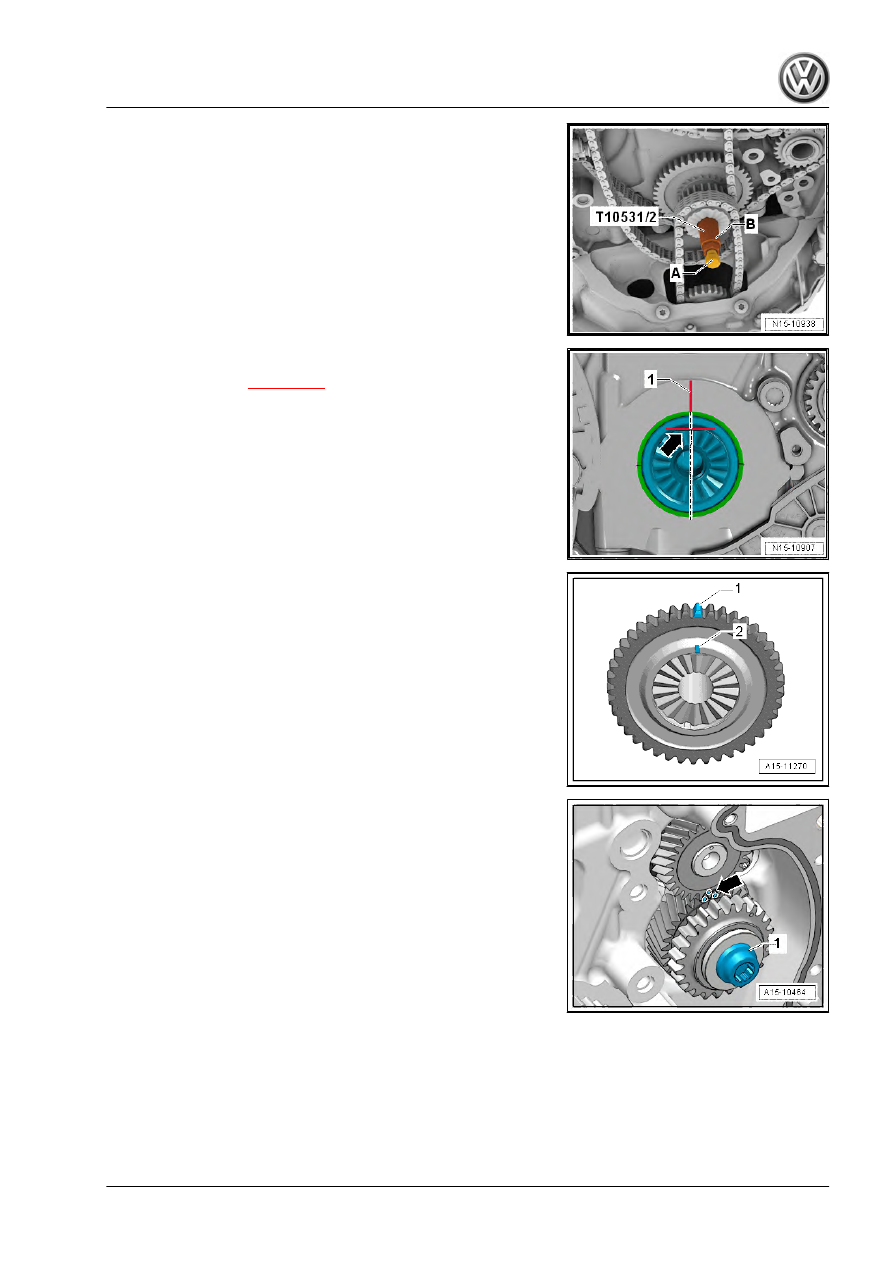
– Loosen tensioning bolt -A-, and unscrew cotter pin -B-.
– Remove triple chain sprocket. To do this, remove drive chain

for oil pump.

– Remove camshaft timing chain.

Installing
• Specified torques 

⇒ page 112

 .

– Check if crankshaft is positioned at TDC. The flat section on

crankshaft -arrow- must be in horizontal position.

– Using a permanent felt tip marker, make a marking on cylinder

block -1-, as shown in illustration.

– Mark tooth -1- of triple chain sprocket which is aligned with

marking -2- using a permanent felt tip marker.

– Turn idler gear and balance shaft so that markings -arrow- are

aligned as shown in illustration. Do not loosen bolt -1-. The

markings on idler gear and balance shaft are difficult to see

and align only after every 7th turn.

121

– Fit drive chain for balance shafts. Position chain links with col‐

oured markings -arrows- at markings on chain sprockets.

– Install guide rail -1-, and tighten bolts -arrows-.

– Fit camshaft timing chain onto camshaft journals with coloured

markings -arrows- properly aligned.

– Fit drive chain for oil pump onto triple chain sprocket.
– Swing triple sprocket towards engine (-direction of arrow-),

and fit it onto crankshaft. The markings -arrows- must align.

     Rep. gr.15 - Cylinder head, valve gear

Volkswagen Technical Site:   http://vwts.ru   http://vwts.info

I - Screw clamping pin - T10531/2- into crankshaft, and tighten it

by hand.
II - Fit turning over tool - T10531/3- . Screw on flange nut -

T10531/4- by hand. Slightly move turning over tool back and forth

with a 32 mm open-end spanner. While doing so, retighten flange

nut until the chain sprocket is securely seated on the crankshaft

splines. Now, tighten tensioning bolt -A-.

– Position link of drive chain for balance shafts with coloured

marking -arrow- at marking of triple sprocket. Install tensioning

rail -1- and guide rail -2-. Tighten bolts -3-.

– Install chain tensioner -1-.

– Make sure that adjustment has been carried out correctly:

chain links with coloured markings -arrows- must be posi‐

tioned at markings on chain sprockets.

123

– Fit camshaft timing chain on inlet camshaft, exhaust camshaft

and crankshaft. Position chain links with coloured markings

-arrows- at the markings on chain sprockets.

– Fit guide rail for camshaft timing chain and tighten bolts -A-.

Note

Have a second mechanic hold the exhaust camshaft.

– Slowly turn exhaust camshaft in direction of arrow -1- until

camshaft clamp - T40271/1- can be withdrawn from sprocket

teeth.

– Carefully relieve load on camshaft until camshaft timing chain

lies against upper guide rail. Hold camshaft in this position.

Caution

Before installing the tensioning plate it is essential to check

whether the coloured chain link is still aligned with the crank‐

shaft marking.

     Rep. gr.15 - Cylinder head, valve gear

– Continue to hold camshaft and install tensioning rail for cam‐

shaft timing chain. Tighten bolt -A-.

– Remove camshaft clamp - T40271/1- .

– Slide camshaft clamp - T40271/2- out of sprocket teeth -2-, if

necessary turning inlet camshaft slightly using spanner -1-.

– Remove camshaft clamp - T40271/2- .

– Depending on version, remove locking pin - T40011- or locking

tool - T40267- .

125

– Check position of coloured chain links relative to markings.

– Install chain tensioner -2-. The retaining clip -arrow- must be

seated in recess in top section of sump. Tighten bolt -1-, and

remove locking pin - T40011- .

– Screw in and tighten bolts -arrows-.

– Fit bearing saddle carefully. Do not cant bearing saddle! Screw

in bolts -arrows- and tighten by hand.

– Tighten bolts -arrows- for bearing saddle 

⇒ page 112

 .

– Install control valve 

⇒ Item 6 (page 113)

 .

     Rep. gr.15 - Cylinder head, valve gear

– Using a 32 mm open-jaw spanner on assembly tool -

T10531/3- , rotate crankshaft 2 full turns in direction of engine

rotation. At “TDC position” the flat section -1- faces upwards.

Note

Due to the ratio, the coloured chain links no longer align with the

markings after the engine has been turned.

Further assembly is basically a reverse of the dismantling se‐

quence.

1.9

Assembly overview - drive chain for balance shaft

1 - Bolt

❑ 9 Nm

2 - Balancer shaft

❑ Renew after removal
❑ Exhaust side
❑ Lubricate bearing with

engine oil

❑ Removing 

⇒ page 132

3 - Tube for balancer shaft

❑ Fitting position

⇒ page 128

4 - Chain tensioner

❑ 85 Nm

5 - Cylinder block
6 - Balancer shaft

❑ Renew after removal
❑ Inlet side
❑ Lubricate bearing with

engine oil

❑ Removing 

⇒ page 129

7 - O-ring

❑ Lubricate with engine oil

8 - Bearing mounting

❑ Lubricate with engine oil
❑ Fitting position

⇒ page 128

9 - Intermediate shaft sprocket

❑ For balancer shaft.
❑ If the securing bolt has

been loosened, the intermediate shaft sprocket must be renewed.

10 - Bolt

❑ 9 Nm

11 - Washer
12 - Securing bolt

❑ If the securing bolt has been loosened, the intermediate shaft sprocket must be renewed.
❑ Tightening sequence 

⇒ page 129

127

13 - Slide rail

❑ For drive chain.

14 - Guide pin

❑ 20 Nm

15 - Tensioning rail

❑ For drive chain.

16 - Guide pin

❑ 20 Nm

17 - Drive chain for balance shafts

❑ Removing and installing 

⇒ page 129

18 - Sprocket

❑ Fitting position 

⇒ page 114

19 - Slide rail

❑ For drive chain.

20 - Guide pin

❑ 20 Nm

Tube for balancer shaft - installation position
• Lug on tube for balance shaft must engage in slot -arrow-.

Bearing mounting - installation position
• Renew O-ring -1- and lubricate with oil
• Dowel pin -arrow- for bearing mounting must engage in bore

in cylinder block

• Lubricate bearing mounting.

     Rep. gr.15 - Cylinder head, valve gear

Chain sprocket - tightening sequence

Caution

The intermediate shaft sprocket must be replaced. Otherwise

no tooth backlash is set - engine damage. The new intermedi‐

ate shaft sprocket is coated with a solid film lubricant that wears

off after a short period and thus automatically sets the tooth

backlash.

– Tighten bolt as follows:
1.

Pre-tighten to 10 Nm using torque wrench.

2.

Turn sprocket.

Chain sprocket must be without play; otherwise loosen bolt and

tighten again.
3.

Tighten to 30 Nm using torque wrench.

4.

Use fixed wrench to turn 90° further.

1.10

Removing and installing drive chain for

balance shaft

The procedure “Removing and installing drive chain for balance

shaft” is part of the procedure “Removing and installing camshaft

timing chain” 

⇒ page 114

 .

1.11

Removing and installing inlet side bal‐

ance shaft

Special tools and workshop equipment required
♦ Puller - T10394-

♦ Puller - T10055-

129

Note

The balance shaft must always be renewed after removing.

Removing:
– Remove toothed belt for coolant pump 

⇒ page 253

 .

– Remove timing chain cover (top) 

⇒ page 91

 .

– Remove lower timing chain cover:

Passat CC 

⇒ page 93

Golf, Eos, Scirocco 

⇒ page 99

Tiguan 

⇒ page 106

– Remove camshaft timing chain and drive chain for balance

shaft 

⇒ page 114

 .

– Remove intermediate gear -1-.

– Unscrew bolt -2- for inlet camshaft balance shaft and pull out

balance shaft.

If balance shaft cannot be pulled out by hand, use puller -

T10394- :

– Insert shell half - T10394/1- from puller - T10394- and turns

upwards in direction of arrow.

     Rep. gr.15 - Cylinder head, valve gear

– Insert puller - T10394- and push locking collar in

-direction of arrow-.

– Screw puller - T10055- into puller - T10394- and force out bal‐

ance shaft in -direction of arrow-.

Installing

Note

Due to the small amount of play between the balance shaft and

cylinder block, the balance shaft may need to be installed chilled.

Check whether the balance shaft can be fitted into the cylinder

block without exerting force. If this is not the case, the balance

shaft must be chilled before installing.

• Specified torques 

⇒ page 127

 .

– Place new balance shaft in freezer compartment for 30 mi‐

nutes or spray with commercially available chilling spray.

– Lubricate balancer shaft bearing with engine oil.

– Install new balancer shaft for inlet camshaft and tighten bolt

-2-.

– Renew O-ring -1- and lubricate with engine oil.
– Lubricate bearing mounting with engine oil and insert

-arrow-; bearing mounting must engage in bore in cylinder

block.

Caution

The intermediate shaft sprocket must be replaced. Otherwise

no tooth backlash is set - engine damage. The new intermedi‐

ate shaft sprocket is coated with a solid film lubricant that wears

off after a short period and thus automatically sets the tooth

backlash.

131

– Mark faces of gear teeth of idler gear with paint -arrows-.
– Insert intermediate gear; marking on balance shaft must be

positioned between markings on faces of gear teeth.

– Tighten bolt for sprocket -1-: tightening sequence

⇒ page 129

 .

– Check markings on intermediate shaft sprocket/balancer shaft

-arrow-.

Note

Due to the ratio, the markings align only after every 7th turn.

– Install drive chain for balance shaft and camshaft timing chain

⇒ page 121

 .

The remaining installation steps are carried out in the reverse se‐

quence. Note the following:
– Renew oil seal for coolant pump drive 

⇒ page 255

 .

1.12

Removing and installing exhaust side

balance shaft

Special tools and workshop equipment required
♦ Puller - T10394-

     Rep. gr.15 - Cylinder head, valve gear

♦ Puller - T10055-

Note

The balance shaft must always be renewed after removing.

Removing:
– Remove timing chain cover (top) 

⇒ page 91

 .

– Remove lower timing chain cover:

Passat CC 

⇒ page 93

Golf, Eos, Scirocco 

⇒ page 99

Tiguan 

⇒ page 106

– Remove camshaft timing chain and drive chain for balance

shaft 

⇒ page 114

 .

– Unscrew bolt -1- and pull out balance shaft.
If balance shaft cannot be pulled out by hand, use puller -

T10394- :

– Insert shell half -T10394/1- from puller - T10394- .

133

– Insert puller - T10394- and push locking collar in

-direction of arrow-.

– Screw puller - T10055- into puller - T10394- and force out bal‐

ance shaft.

Installing:

Note

Due to the small amount of play between the balance shaft and

cylinder block, the balance shaft may need to be installed chilled.

Check whether the balance shaft can be fitted into the cylinder

block without exerting force. If this is not the case, the balance

shaft must be chilled before installing.

• Specified torques 

⇒ page 127

 .

– Check installation position of tube for balancer shaft -arrow-.
The lug -arrow- must be on top. It functions as an anti-twist device.

Note

To get the tube into installation position, it must be squeezed to‐

gether slightly. Insert 2-hole pin wrench - 3212- in front bores of

tube and press together. Then insert pipe with 2-hole pin wrench

- 3212- .

– Place new balance shaft in freezer compartment for 30 mi‐

nutes or spray with commercially available chilling spray.

– Lubricate balancer shaft bearing with engine oil.
– Install balance shaft for exhaust camshaft.

– Before tightening bolt -1-, check that balance shaft rests flat

against crankcase.

Note

If the balancer shaft does not rest flat, the pipe for balancer shaft

must be inserted again.

– Install drive chain for balance shaft and camshaft timing chain

⇒ page 121

 .

Further assembly is basically a reverse of the dismantling se‐

quence.

     Rep. gr.15 - Cylinder head, valve gear

1.13

Checking valve timing

Special tools and workshop equipment required
♦ Dial gauge - VAS 6079-

♦ Dial gauge adapter - T10170 A-

♦ Depth gauge
– Remove timing chain cover (top) 

⇒ page 91

 .

– Remove right wheel and right wheel housing liner.
– Using 24 mm socket, turn crankshaft via vibration damper in

normal direction of rotation until markings -arrows- are almost

at top.

– Remove spark plug from cylinder 1.

135

– Screw dial gauge adapter - T10170/A- into spark plug hole to

stop.

– Insert dial gauge - VAS 6079- with extension - T10170A/1- as

far as it will go and secure in place with self-locking nut

-arrow-.

– Slowly turn crankshaft in engine DOR to maximum needle de‐

flection. Once maximum needle deflection is reached (reverse

point of needle), piston is at »TDC«.

Note

If the crankshaft has been turned beyond »TDC« turn engine an‐

other two revolutions in direction of engine rotation. Do not turn

engine in opposite direction of engine rotation!

– Measure distance from left outer edge of web -A- to marking

-B- on inlet camshaft.

• Specification: 61 to 64 mm.

– If the specified value is achieved, measure the distance be‐

tween the marking on the inlet camshaft -B- and the marking

on the exhaust camshaft -C-.

• Specification: 124 to 126 mm

Note

An offset of one tooth results in a deviation of approx. 6 mm from

the specified value. If an offset is found, the timing chain must be

re-fitted.

     Rep. gr.15 - Cylinder head, valve gear

2

Cylinder head

Assembly overview - cylinder head 

⇒ page 137

 .

Removing and installing engine cover panel 

⇒ page 141

 .

Removing and installing cylinder head 

⇒ page 142

 .

Compression test 

⇒ page 178

 .

Removing and installing vacuum pump 

⇒ page 180

 .

2.1

Assembly overview - cylinder head

Note

If the cylinder head bolts have multi-point sockets and a shoul‐

der, the camshafts must be removed before the cylinder head

bolts are unscrewed.

When assembling, renew self-locking nuts, bolts that are tight‐

ened by turning further angle, as well as seals and gaskets.

The plastic protectors fitted to protect the open valves must

only be removed immediately before fitting the cylinder head.

1 - Cylinder head gasket

❑ Renew
❑ Observe installation po‐

sition: Part number to

cylinder head

2 - Bolt

❑ 25 Nm

3 - Transportation shackle
4 - Bolt

❑ Tightening sequence

⇒ page 140

5 - Cylinder head

❑ Removing and installing

⇒ page 142

❑ Check for distortion

⇒ page 140

 .

❑ Renew oil non-return

valve in cylinder head

⇒ page 140

6 - Cylinder head bolt

❑ Renew
❑ Note sequence when

loosening 

⇒ page 139

 .

❑ Note correct sequence

when tightening

⇒ page 140

 .

7 - O-ring

❑ Renew
❑ Lubricate with engine oil

8 - Plug

❑ 5 Nm

137

❑ With ball head for engine cover panel

9 - Cap

❑ With seal

10 - O-ring

❑ Renew
❑ Lubricate with engine oil

11 - Plug
12 - Bracket
13 - Bolt

❑ 9 Nm

14 - Heat shield
15 - Bolt

❑ 20 Nm

16 - Bolt

❑ 20 Nm

17 - To intake hose/turbocharger
18 - Breather pipe
19 - O-ring

❑ No replacement part

20 - Seal

❑ No replacement part

21 - Engine cover panel
22 - Bolt

❑ Self-tapping
❑ Tightening sequence 

⇒ page 139

23 - Crankcase ventilation

❑ Note correct sequence when tightening 

⇒ page 139

 .

24 - To intake manifold
25 - Seal

❑ Renew if damaged

26 - Seal

❑ Renew

27 - Vacuum pump

❑ Removing and installing 

⇒ page 180

28 - Securing bolts for vacuum pump

❑ Engine codes CAWA, CAWB, CBFA, CCTA, CCTB, BZB, CGYA: 9 Nm
❑ Engine codes CCZA, CCZB, CCZC, CCZD, CDAA, CDAB: 8 Nm + additional 180° turn

Renew after removal

29 - 9 Nm

❑ Only engine code CBFA

30 - Secondary air inlet valve - N112-

❑ Only engine code CBFA
❑ Removing and installing 

⇒ page 559

31 - Seal

❑ Only engine code CBFA

     Rep. gr.15 - Cylinder head, valve gear

❑ Renew

32 - Retaining plate
33 - Bolt

❑ 9 Nm

34 - Union

❑ Engine code CBFA: before removal, secondary air inlet valve - N112- must be removed 

⇒ page 559

35 - O-ring

❑ Renew
❑ Lubricate with coolant

36 - Bolt

❑ 25 Nm

37 - Transportation shackle
38 - Bolt

❑ 9 Nm

39 - Hall sender - G40-
40 - Partition

Crankcase breather system - tightening torque
– Tighten bolts for crankcase breather in the sequence

-1 … 10- to 11 Nm.

Loosening cylinder head bolts

Note

If the cylinder head bolts have multi-point sockets and a shoul‐

der, the camshafts must be removed before the cylinder head

bolts are unscrewed.

If a cylinder head cover without sealing plugs for the cylinder

head bolts -5- is installed, the camshafts must be removed.

– Unscrew bolts -arrows-.
– Slacken cylinder head bolts in the sequence -1 … 5-.

139

Cylinder head - tightening sequence, camshaft installed
– Tighten cylinder head bolts in the sequence -1 … 5- as follows:
1 - Tighten initially to 40 Nm using torque wrench
2 - Turn 90° further using rigid wrench
3 - Turn 90° further using rigid wrench
– Then tighten bolts -arrows-.
1 - Pre-tighten bolts to 8 Nm
2 - Turn bolts 90° further using rigid wrench

Cylinder head - tightening sequence, camshaft removed
– Tighten cylinder head bolts in the sequence -1 … 10- as fol‐

lows:

1 - Tighten initially to 40 Nm using torque wrench
2 - Turn 90° further using rigid wrench
3 - Turn 90° further using rigid wrench
– Then tighten bolts -arrows-.
1 - Pre-tighten bolts to 8 Nm
2 - Turn bolts 90° further using rigid wrench

Checking cylinder head for distortion
– Use straight edge 500 mm - VAS 6075- and feeler gauge to

measure cylinder head for distortion at several points.

♦ Max. permissible distortion: 0.05 mm.

2.2

Renewing oil non-return valve in cylin‐

der head

Special tools and workshop equipment required
♦ Hooks e.g. assembly tool - T10118-

     Rep. gr.15 - Cylinder head, valve gear

Removing
– Remove cylinder head 

⇒ page 142

 .

– Pull out oil non-return valve -arrow- with a suitable hook, e.g. 

assembly tool - T10118- .

Installing
– Clean oil channels.
– Moisten seal for new oil non-return valve with clean engine oil.
– Insert oil non-return valve by hand into cylinder head to stop.
– Install cylinder head 

⇒ page 142

 .

2.3

Removing and installing engine cover

Removing
– Pull engine cover panel off upwards at securing points

-arrows-.

Installing

– When fitting, make sure that rubber buffers are correctly in‐

serted in mountings.

– Press engine cover panel back carefully into its retainers.
– To prevent damage, do not strike engine cover panel with your

fist or a tool.

141

2.4

Removing and installing cylinder head

Note

If the cylinder head bolts have multi-point sockets and a shoul‐

der, the camshafts must be removed before the cylinder head

bolts are unscrewed.

If cylinder head bolts with a multipoint socket head and shoul‐

der are used for installation, the cylinder head bolts must be

inserted before the camshafts are installed.

If a cylinder head cover without sealing plugs for the cylinder

head bolts -5- is or is going to be installed, the camshafts must

be removed.

Checking guide rail version:

Note

Depending on the respective repair work to be carried out and on

the version of the guide rail, different procedures apply. Please

check which guide rail is installed before starting work.

– Remove timing chain cover (top) 

⇒ page 91

 .

– Check guide rail -1- in area indicated by -arrow-.
A - Long guide rail
B - Short guide rail
Removing cylinder head, if a »short« guide rail is installed and the

camshaft timing chain shall remain installed:

Procedure

⇒ “2.4.1 Removing and installing cylinder head”, page 142

 .

Removing cylinder head, if a »short« guide rail is installed and the

camshaft timing chain is to be removed as well:

Procedure

⇒ “2.4.2 Removing and installing cylinder head and camshaft

timing chain”, page 165

 .

Removing cylinder head, if a »long« guide rail is installed:

Procedure

⇒ “2.4.2 Removing and installing cylinder head and camshaft

timing chain”, page 165

 .

2.4.1

Removing and installing cylinder head

     Rep. gr.15 - Cylinder head, valve gear

Special tools and workshop

equipment required

♦ Assembly tool - T10352-
♦ Engine codes CCZA, CCZB, CCZC, CCZD, CDAA, CDAB:

assembly tool - T10352/1-

♦ Counter-hold tool - T10355-
♦ Pin - T40011-
♦ Assembly lever - T40243-
♦ Locking tool - T40267-
♦ Camshaft clamp - T40271-

143

♦ Torque wrench - V.A.G 1331-
♦ Torque wrench - V.A.G 1332-
♦ Workshop hoist - VAS 6100-
♦ Engine plug set - VAS 6122-
♦ Drip tray for workshop hoist - VAS 6208-
♦ Polydrive cylinder head bolts: Special wrench, long reach -

T10070-

♦ Cylinder head bolts with multi-point socket: Multi-point socket

12 mm

     Rep. gr.15 - Cylinder head, valve gear

♦ Lifting tackle - 2024 A-

♦ Bracket - T10014-

♦ Puller - T40039-

Removing:

Note

Fit cable ties in the original positions when installing.

Always seal open channels of the intake and exhaust systems

with suitable plugs. For example, those from engine bung set

- VAS 6122- .

– Pull off engine cover panel 

⇒ page 141

 .

– Remove air filter housing 

⇒ page 467

 .

145

– Release hose clip -2-.
– Unscrew bolt -4-.
– Disconnect electrical connector -arrow- and move electrical

wires clear.

WARNING

Danger of scalding by steam and hot coolant.
On a warm engine, the cooling system is under high pressure.
Cover filler cap on expansion tank with a cloth and open care‐

fully to release pressure.

– Open filler cap on expansion tank.
– Remove front exhaust pipe with catalytic converter:

Passat, CC 

⇒ page 526

Golf, Eos, Scirocco 

⇒ page 542

Tiguan 

⇒ page 552

– Remove front right wheel.
– Remove noise insulation ⇒  General body repairs, exterior;

Rep. gr.  50 ; Noise insulation .

– Remove right wheel housing liner ⇒  General body repairs,

exterior; Rep. gr.  66 ; Wheel housing liner .

– Drain coolant 

⇒ page 241

 .

– Remove charge air hose -A-.

– Remove bolt -1- and take out air pipe downwards.

     Rep. gr.15 - Cylinder head, valve gear

– Unscrew bolts -arrows-.
– Remove air pipe (lift clips -items 1 and 2-).

– Separate electrical wiring connections -1 and 2- and place

electrical wiring to one side -arrows-.

Vehicles with auxiliary heater:
– Unscrew bolts -1 and 2- and move coolant pipes to the left.
Vehicles with all-wheel drive:
– Remove right drive shaft ⇒  Running gear, axles, steering;

Rep. gr.  40 ; Removing and installing drive shafts .

All vehicles:
– Remove bolts -1 and 2- and detach support for turbocharger.

147

– Remove banjo bolt -2- and move coolant pipe clear to one

side.

Vehicles with front-wheel drive:
– Remove bolts -1- on oil return line.
Vehicles with all-wheel drive:
– Remove bolts of oil return line at crankcase.
All vehicles:
– Remove bolt -3- on oil supply line.
– Only vehicles with sound generator: Remove charge air duct

to sound generator.

– Pull connector -1- off camshaft control valve 1 - N205- .

– Detach connectors from ignition coils and place wiring harness

to one side.

– Remove ignition coils using puller - T40039- .

Engine codes BZB, CAWA, CAWB, CGYA, CDAA:
– Unscrew bolt -arrow- for air pipe.
– Remove air pipe, loosening hose clip -1- to do so.
– Press release tabs -2-, and pull crankcase breather off air

hose.

     Rep. gr.15 - Cylinder head, valve gear

– Disconnect crankcase breather hose -1-.
– Remove bolts -arrows- and remove crankcase breather.

Engine codes CBFA, CCTA, CCTB:
– Disconnect crankcase breather hose -1-.
– Unscrew bolts -arrows-.

– Unscrew bolt -arrow- for air pipe.
– Loosen hose clip -1- and remove air pipe together with crank‐

case breather.

All:

WARNING

The fuel line is under pressure.
Fuel poses danger of injury to eyes and skin.
Wear protective goggles and protective clothing to avoid injury

and contact with the skin. Wrap a cloth around the connection

before loosening hose connections. Then reduce pressure by

carefully opening the connection.

– Detach lines -1 to 3- from the fuel transfer point.

1) Breather hose
2) Vacuum line (only CBFA, CCTA, CCTB)
3) Fuel supply line

149

– Disconnect coolant line to coolant expansion tank -arrow-.

– Remove coolant hoses -arrows- from coolant pipe.
– Unbolt earth cable -3- and loosen bolt -4-.

– Pull off vacuum hoses -arrows-.

– Unscrew bolts -1…3- and remove heat shield together with

coolant pipe.

– Unscrew oil supply line -4- from turbocharger.

     Rep. gr.15 - Cylinder head, valve gear

Note

Unscrew bolt -2- from heat shield using a 6 mm hex key -A-. The

hexagon faces must be at least 5 cm long -B-. A socket which

tapers to 6 mm at the tip is too thick.

– Pull electrical connector -2- from fuel pressure regulating valve

- N276- .

Engine code CBFA:
– Pull connector -A- and hose -B- from secondary air inlet valve

- N112- .

– Loosen coolant pipe by unscrewing bolts -arrows-.

151

All:
– Pull coolant hose from union on side of cylinder head.
– Separate electrical connectors -1 to 4-.
– Place electrical cable -5- to one side.
– Pull off vacuum line -6- leading to activated charcoal filter.

Golf, Scirocco:
– Pull off breather line -1-, release activated charcoal filter -A-

and remove upwards -B-.

All:
– Separate electrical connectors -1- and pull out connectors

from retainer.

– Separate electrical connectors -2 to 4-.

– Unscrew bolts -arrows- and detach coolant pipes from intake

manifold.

     Rep. gr.15 - Cylinder head, valve gear


Content      ..     3      4      5      6     ..