Volkswagen 4-cyl. injection engine (1.8 and 2.0 l engine, chain drive). Manual (Edition 08.2018) - page 3
 

  Index      Manuals     Volkswagen 4-cyl. injection engine (1.8 and 2.0 l engine, chain drive). Manual (Edition 08.2018). Workshop Manual (Edition 08.2018)


Search            copyright infringement  


Content      ..     1      2      3      4      ..


Volkswagen 4-cyl. injection engine (1.8 and 2.0 l engine, chain drive). Manual (Edition 08.2018) - page 3


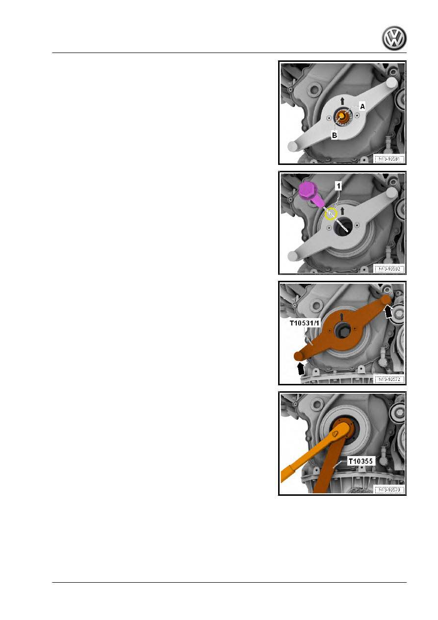
– Unscrew flange nut -A-, and loosen clamping pin -B-. Unscrew

clamping pin , and remove it together with turning over tool .

– Screw in new vibration damper bolt with lubricated O-ring -1-

by hand.

– Unscrew knurled screws -arrows-, and remove support -

T10531/1- .

– Tighten vibration damper bolt using counter hold tool -

T10355- .

57
– Screw in new securing bolts -arrows-.
Further assembly is basically a reverse of the dismantling se‐

quence.
Specified torques

⇒ “1.1 Assembly overview - poly V-belt drive”, page 37

1.8

Renewing oil seal for vibration damper

Special tools and workshop equipment required
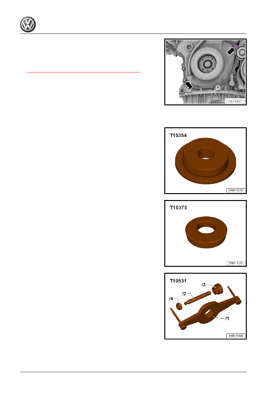
♦ Thrust piece - T10354-

♦ Thrust plate - T10375-

♦ Flange nut - 10531/4- from assembly tool - T10531-

     Rep. gr.13 - Crankshaft group

♦ Extractor hook - T40274-

Removing
– Remove vibration damper 

⇒ page 51

 .

• Clamping pin - T10531/2- is inserted.
– Using extractor hook - T40274- , pull out seal -arrow-.

Installing
– Clean contact surface and sealing surface.
– Slide seal -arrow- onto thrust piece - T10354- .
• Closed side of oil seal faces towards thrust piece - T10354- .

– Slide seal -arrow- with thrust piece - T10354- onto clamping

pin - T10531/2- , and fit it to lower timing chain cover.

59

– In addition, fit thrust pad - T10375- , and screw on flange nut

- 10531/4- .

– Using open-end spanner, AF 21, tighten flange nut until seal

has been pressed in as far as stop.

Note

Renew bolt for vibration damper.

Renew O-ring.

Further assembly is basically a reverse of the dismantling se‐

quence. During this procedure, observe the following:
– Install vibration damper 

⇒ page 51

 .

     Rep. gr.13 - Crankshaft group

2

Cylinder block, gearbox end

Assembly overview - sealing flange on gearbox side and dual-

mass flywheel/drive plate 

⇒ page 61

 .

Removing and installing dual-mass flywheel 

⇒ page 62

 .

Removing and installing drive plate 

⇒ page 63

Removing and installing sealing flange on gearbox side

⇒ page 65

 .

2.1

Assembly overview - sealing flange on gearbox side and dual-mass fly‐

wheel/drive plate

1 - Cylinder block

❑ Removing and installing

crankshaft

⇒ page 72

 .

❑ Dismantling and assem‐

bling pistons and con‐

rods 

⇒ page 80

2 - Dowel pin

❑ Not installed

3 - Sealing flange on gearbox

side

❑ With seal
❑ Renew only as com‐

plete unit

❑ Removing and installing

⇒ page 65

4 - Bolt

❑ Tightening sequence

⇒ page 62

5 - Intermediate plate

❑ Must seat on dowel

sleeves.

❑ Do not damage or bend

when assembling.

❑ Is fitted onto sealing

flange 

⇒ page 62

6 - Bolt

❑ For dual-mass flywheel/

drive plate

❑ 60 Nm + 90° (

1

/4 turn)

further

❑ Renew

7 - Dual mass flywheel/drive plate

❑ Removing and installing dual-mass flywheel 

⇒ page 62

❑ Removing and installing drive plate 

⇒ page 63

❑ Drive plate installation position: »collar« points towards engine
❑ Can only be installed in one position, holes are offset.

8 - Dowel pin

❑ Not installed

61

Sealing flange at gearbox end - tightening sequence
– Tighten bolts -1 to 8- in the sequence shown:
♦ 1. Screw in and tighten bolts by hand.
♦ 2. Tighten bolts to 9 Nm.

Installing intermediate plate
– Hook intermediate plate onto sealing flange and slide onto

dowel sleeves -arrows-.

2.2

Removing and installing dual-mass fly‐

wheel

Special tools and workshop equipment required
♦ Counter-hold tool - 3067-

Removing
– Remove gearbox ⇒  Power transmission; Rep. gr.  37 ; Re‐

moving and installing gearbox .

Caution

In order to avoid destruction of the dual-mass flywheel, you are

not  allowed  to  undo  the  bolts  -B-  with  a  pneumatic/impact

screwdriver. It is only permissible to remove the bolts by hand.

     Rep. gr.13 - Crankshaft group

– Rotate the dual-mass flywheel -A- so that the bolts -B- align

centrally with the holes -arrows-.

– When unscrewing bolts -B-, ensure that none of the bolt heads

come into contact with the dual-mass flywheel -arrows-. The

flywheel will otherwise be damaged when the bolts are un‐

screwed further.

– Insert counterhold - 3067- in hole on cylinder block -B-.
– Unscrew dual-mass flywheel.
Installing
Installation is carried out in the reverse order. When installing,

note the following:
• Specified torque 

⇒ Item 6 (page 61)

– Use new bolts for securing.

– Insert counter hold - 3067- in hole on cylinder block -A-.

2.3

Removing and installing drive plate

Special tools and workshop equipment required

63

♦ Counter-hold tool - VW 558-

♦ Depth gauge
♦ Hexagon bolt M8×40 and hexagon nut M8
– Remove gearbox ⇒  Power transmission; Rep. gr.  37 ; Re‐

moving and installing gearbox .

Preparing counter hold tool - VW 558- :
– Tighten hexagon bolt M8x40 -A- with hexagon nut on clutch

counter-hold tool - VW 558- .

Loosening and tightening drive plate:

– Insert counter hold - VW 558- in cylinder block and drive plate

as shown.

Installation position of counter hold: -A- to loosen, -B- to tighten.

Installing drive plate:
– Fit drive plate without washer -A- first.
– Fit used securing bolts -3- and tighten to 30 Nm.

     Rep. gr.13 - Crankshaft group

– Check dimension between drive plate and cylinder block at

three points and calculate average.

Note

Measure through hole in drive plate to milled surface of cylinder

block. If measuring on the intermediate plate, the plate thickness

must be taken into account.

• Specification measured without intermediate plate: 19.5…

21.1 mm

• Specification measured with intermediate plate: 18.8…

20.4 mm

If the specification is not reached, replace all securing bolts and

tighten.

If specification is not attained:
– Remove drive plate again and fit shim -A-. Tighten bolts -3-

again to 30 Nm.

– Repeat measurement. If the specification is not reached, re‐

place all securing bolts and tighten.

• Specified torque 

⇒ Item 6 (page 61)

2.4

Removing and installing sealing flange

on gearbox side

Note

There are 2 versions of the sealing flange. Check which ver‐

sion must be installed.

Version -A-: Sealing lip -1- faces gearbox (outwards).

Version -B-: Sealing lip -1- faces engine. This sealing flange

also has a dust lip -2-.

Removing and installing version -A- 

⇒ page 65

 .

Removing and installing version -B- 

⇒ page 68

 .

2.4.1

Removing and installing sealing flange

on gearbox side, version A sealing lip

faces outwards

Special tools and workshop equipment required

65

♦ Assembly sleeve - T20097-

♦ Hand drill with plastic brush attachment
♦ Safety glasses
♦ Sealant ⇒  Electronic parts catalogue (ETKA)
Removing
• Gearbox is removed.
• Dual mass flywheel removed 

⇒ page 62

 or drive plate removed

⇒ page 63

 .

– Detach intermediate plate from sealing flange and dowel pins

-arrows-.

– Unscrew bolts -1 to 8-.
– Remove sealing flange.
Installing

Note

Observe use-by date of silicone sealant.

The sealing flange must be installed within 5 minutes of ap‐

plying the silicone sealant.

In order to prevent the lubrication system from being soiled

with sealant residue cover the open section of the sump with

a clean cloth.

Caution

Risk of eye injury caused by sealant residue.

♦ Wear protective goggles.

     Rep. gr.13 - Crankshaft group

– Remove sealant residue from cylinder block, e.g. with rotating

plastic brush.

– Clean sealing surfaces. They must be oil and grease free.

– Cut off nozzle on tube at front marking (∅ of nozzle approx. 2

mm).

– Apply silicone sealing compound bead, as shown in diagram,

to clean sealing surface of sealing flange.

♦ Thickness of sealant bead: 2 to 3 mm

– Clean crankshaft pins carefully.
– Check assembly sleeve ; it must be free of any deformation or

sharp edges.

– Fit assembly sleeve - T20097- onto crankshaft journal -A-.
– Fit sealing flange over assembly sleeve - T20097- onto crank‐

shaft journal.

– Remove assembly sleeve - T20097- .

67

– Tighten new bolts evenly in the sequence shown.

Stage

Bolts

Specified torque/turning further angle

1.

-1 … 8-

Screw in by hand as far as stop

2.

-1 … 8-

9 Nm

Note

After installing the sealing flange, wait about 30 minutes for the

sealant to dry. Only then fill with engine oil.

Further assembly is basically a reverse of the dismantling se‐

quence.
Specified torques

⇒ “2.1 Assembly overview - sealing flange on gearbox side

and dual-mass flywheel/drive plate”, page 61

2.4.2

Removing and installing sealing flange

on gearbox side, version B sealing lip

faces engine

Special tools and workshop equipment required
♦ Guide piece - T10122/6- or -T10122/6A- from fitting tools -

T10122B- or -T10122C-

♦ Assembly aid - T10122/1- from fitting tools - T10122B- or -

T10122C-

♦ Hand drill with plastic brush attachment
♦ Safety glasses
♦ Sealant ⇒  Electronic parts catalogue (ETKA)
Removing
• Gearbox is removed.

     Rep. gr.13 - Crankshaft group

• Dual mass flywheel removed 

⇒ page 62

 or drive plate removed

⇒ page 63

 .

– Detach intermediate plate from sealing flange and dowel pins

-arrows-.

– Unscrew bolts -1 to 8-.
– Prise off sealing flange.
Installing

Note

Observe use-by date of silicone sealant.

The sealing flange must be installed within 5 minutes of ap‐

plying the silicone sealant.

In order to prevent the lubrication system from being soiled

with sealant residue cover the open section of the sump with

a clean cloth.

Caution

Risk of eye injury caused by sealant residue.

♦ Wear protective goggles.

– Remove sealant remaining on cylinder block with flat scraper

or rotating plastic brush.

– Clean sealing surfaces. They must be oil and grease free.
– Clean crankshaft journal. If there is any rust, lightly coat crank‐

shaft journal with oil.

– Cut off nozzle on tube at front marking (∅ of nozzle approx.

2 mm).

69

– Apply silicone sealant as shown to clean sealing surface of

sealing flange.

♦ Thickness of sealant bead: 2 to 3 mm.

Note

The sealing flange must be installed within 5 minutes after ap‐

plying the silicone sealant.

The bead of sealant must not be thicker than specified, other‐

wise excess sealant can enter the sump and obstruct the

strainer in the oil intake pipe.

Check sealing flange; it must be free of kinks and damage.

The sealing lip must face engine following installation. If the

sealing lip »folds out« during installation, oil leaks may occur.

– Check guide - T10122/6- -(B)-; it must be clean and free of

sharp edges.

– Attach assembly aid - T10122/1- -(A)- to guide - T10122/6-

-(B)-.

– Push sealing flange -C-, leading with the outer side, onto guide

-B-.

– Remove assembly aid -A-.

     Rep. gr.13 - Crankshaft group

– Put guide -A- with sealing flange -B- onto crankshaft journal.
– It is not necessary to tighten the bolts -arrows-.
– Push sealing flange -B- over guide -A- onto crankshaft journal.
– Remove guide -A-.

– Tighten new bolts evenly in the sequence shown.

Stage

Bolts

Specified torque/turning further angle

1.

-1 … 8-

Screw in by hand as far as stop

2.

-1 … 8-

9 Nm

Note

After installing the sealing flange, wait about 30 minutes for the

sealant to dry. Only then fill with engine oil.

Further assembly is basically a reverse of the dismantling se‐

quence.
Specified torques

⇒ “2.1 Assembly overview - sealing flange on gearbox side

and dual-mass flywheel/drive plate”, page 61

71

3

Crankshaft

Assembly overview - crankshaft 

⇒ page 72

 .

Tightening sequence - crankshaft 

⇒ page 73

 .

Removing and installing sender wheel 

⇒ page 73

 .

Allocation of crankshaft bearing shells 

⇒ page 74

 .

Pulling needle bearing out of and driving into crankshaft

⇒ page 75

 .

Crankshaft dimensions 

⇒ page 77

 .

Measuring axial clearance of crankshaft 

⇒ page 77

 .

Measuring radial clearance of crankshaft 

⇒ page 78

 .

3.1

Assembly overview - crankshaft

Note

Secure engine to repair stand using engine and gearbox support

- VAS 6095- when dismantling/assembling engine 

⇒ page 18

 .

1 - Cylinder block

❑ If the cylinder block is re‐

newed, the bearing

shells must be realloca‐

ted to cylinder block

⇒ page 74

2 - Bearing shell for cylinder

block

❑ With oil groove.
❑ Do not interchange

used bearing shells

(mark).

❑ Marking of crankshaft

bearing shells

⇒ page 74

3 - Crankshaft

❑ After removing, place it

down so that the sender

wheel -item 5- is not

damaged and the crank‐

shaft does not rest on

the sender wheel

❑ If the crankshaft is re‐

newed, the bearing

shells must be realloca‐

ted to bearing cap

⇒ page 74

❑ Axial clearance

⇒ page 77

❑ Radial clearance

⇒ page 78

❑ Do not rotate crankshaft

when checking radial

clearance

❑ Crankshaft dimensions

⇒ page 77

 .

     Rep. gr.13 - Crankshaft group

❑ Removing and installing 

⇒ page 73

4 - Bearing shell

❑ Without oil groove.
❑ Do not interchange used bearing shells (mark).
❑ Marking of crankshaft bearing shells 

⇒ page 74

5 - Bolt

❑ Observe tightening sequence 

⇒ page 73

❑ Renew

6 - Bearing cap

❑ Bearing cap 1: belt pulley end.
❑ Bearing shell retaining lugs in cylinder block and bearing caps must align.

7 - Bolt

❑ 10 Nm + 

1

/4 turn (90°) further

❑ Renew
❑ Sender wheel must be renewed if bolts are loosened 

⇒ page 73

8 - Sender wheel

❑ For engine speed sender - G28-
❑ Can only be installed in one position, holes are offset.
❑ Always renew sender wheel if securing bolts have been unscrewed
❑ Removing and installing 

⇒ page 73

9 - Thrust washers

❑ For bearing 3

10 - Bolt

❑ Observe tightening sequence 

⇒ page 73

❑ Renew

Crankshaft tightening sequence
– Tighten crankshaft bolts in the sequence -1 … 5- as follows:
1 - Tighten bolts -1 to 10- and -arrows- by hand.
2 - Pre-tighten bolts -1 to 10- to 65 Nm.
3 - Turn bolts -1 to 10- 90° further using a rigid wrench.
4 - Pre-tighten bolts -arrows- to 20 Nm.
5 - Turn bolts -arrows- 90° further using a rigid wrench.

3.1.1

Removing and installing sender wheel

– Remove engine.
– Remove crankshaft sealing flange 

⇒ page 65

 .

– Remove upper part of sump 

⇒ page 218

 .

73

– Remove camshaft timing chain and drive chain for balance

shaft 

⇒ page 114

 .

– Unscrew conrod bearing cap.
– Remove crankshaft bearing cap.
– Remove crankshaft and unscrew sender wheel.
– Renew sender wheel -2- each time bolts -1- are loosened.

Note

The second time the bolts are tightened, the contact points in

the sender wheel for the countersunk heads are deformed so

far that the bolt heads seat on the crankshaft -3-, -arrows- and

the sender wheel is »loose« under the bolts.

Sender wheel can only be installed in one position. The holes

are offset.

• Specified torque 

⇒ page 72

3.1.2

Allocation of crankshaft bearing shells

(classification)

Bearing shells of the correct thickness are allocated to the cylin‐

der block at the factory. Coloured dots are used to identify the

thickness of the bearing shells.
Which bearing shell is to be inserted at each place in the cylinder

block (upper bearing shell) is marked by letters on the lower seal‐

ing surface or on the front side of cylinder block.
Which bearing shell is to be inserted at each place in bearing cap

(lower bearing shell) is marked by letters on the crankshaft.
The first letter is allocated to bearing cap 1, the second to bearing

cap 2, etc.
Cylinder block:
The marking on the cylinder block can be found engraved either

in the sump sealing surface or in the front end (gearbox side) of

the cylinder block.

     Rep. gr.13 - Crankshaft group

Identification on cylinder block is allocated to upper bearing shell

(bearing shell for cylinder block).
– Make a note of the letters and determine the colour marking

for installation with regard to the table.

Crankshaft:
Identification on crankshaft is allocated to lower bearing shell

(bearing shell for bearing cap).
– Make a note of the letters and determine the colour marking

for installation with regard to the table.

S

=

black

R

=

red

G

=

yellow

B

=

blue

W

=

white

3.2

Pulling needle bearing out of and driving

into crankshaft

Only vehicles with a dual clutch gearbox
Special tools and workshop equipment required
♦ Counter support, e.g. KUKKO 22-1 - VAS 251 621-

75

♦ Internal puller - VAS 251 635-

♦ Drift - VW 207 C-

Condition:
• The front edges of the inner puller must be free of chips.
• Gearbox has been removed.
Pulling out needle roller bearing
– Pull out needle bearing -1- with internal puller - VAS 251 635-

-A- and counter support, e.g. KUKKO 22-1 - VAS 251 621-

-B- from crankshaft -2-.

– The internal puller must be positioned behind the needle-and-

cage assembly -arrow-.

     Rep. gr.13 - Crankshaft group

Installing
– Clean bearing seat in crankshaft and apply as thin coating of

grease.

– Drive needle bearing into crankshaft to installation depth using

drift - VW 207 C- .

Installation depth: dimension -a- = 2.0 mm

Note

If the needle bearing is inadvertently driven in too far, it must be

renewed because it will be damaged when it is pulled out again.

3.3

Crankshaft dimensions

(Dimensions in mm)

Honing dimension

1)

Main journal ∅

Conrod journal ∅

Basic dimension

  58.00

    47.80


1)

 No provision has yet been made to recondition worn crank‐

shafts.

3.4

Measuring axial clearance of crankshaft

Special tools and workshop equipment required

77

♦ Universal dial gauge holder - VW 387-

♦ Dial gauge - VAS 6079-

Procedure
– Screw dial gauge - VAS 6079- with universal dial gauge holder

- VW 387- onto cylinder block and set against crankshaft

cheek with 2 mm projection.

– Push crankshaft against dial gauge by hand and set dial gauge

to “0”.

– Press crankshaft away from dial gauge and read value.
Axial clearance:
• New: 0.07 to 0.23 mm
• Wear limit: 0.30 mm.

3.5

Measuring radial clearance of crank‐

shaft

Special tools and workshop equipment required
♦ Plastigage
Procedure

Note

Do not interchange used bearings.

Bearing shells worn down to nickel layer must be renewed.

– Remove main bearing caps and clean bearing caps and jour‐

nals.

– Place Plastigage onto bearing journal or into bearing shells

according to width of bearing.

• The Plastigage must rest in the middle of the bearing shell.

     Rep. gr.13 - Crankshaft group

– Fit main bearing caps and tighten to 60 Nm without rotating

crankshaft.

– Remove main bearing caps again.
– Compare width of Plastigage with measurement scale:
Radial clearance:
• New: 0.017 to 0.037 mm
• Wear limit: 0.15 mm.

79

4

Pistons and conrods

⇒ “4.1 Assembly overview - pistons and conrods”, page 80
⇒ “4.2 Removing and installing pistons”, page 83
⇒ “4.3 Checking pistons and cylinder bores”, page 84
⇒ “4.4 Separating new conrod”, page 86
⇒ “4.5 Checking radial clearance of conrods”, page 87

4.1

Assembly overview - pistons and conrods

1 - Bolts

❑ Renew after removal
❑ Apply engine oil to

thread and contact sur‐

face

❑ Use old bolts to meas‐

ure radial clearance.

❑ 45 Nm +90°

2 - Conrod bearing cap

❑ Observe installation po‐

sition

❑ Conrod bearing cap on‐

ly fits in one position and

only on the appropriate

conrod due to the break‐

ing procedure (crack‐

ing) separating the cap

from the conrod

❑ Mark allocation to cylin‐

der and conrod in colour

-A-

❑ Installation position:

Marking -B- faces to‐

wards pulley end.

❑ Separating new conrod

⇒ page 86

 .

3 - Bearing bushes

❑ Fitting position

⇒ page 81

❑ Renew worn bearing

shells

❑ Apply engine oil before

installing

❑ Axial clearance

♦ New: 0.10 … 0.35 mm
♦ Wear limit: 0.40 mm

❑ Measuring radial clearance 

⇒ page 87

4 - Connecting rod

❑ Renew as set only.
❑ Mark allocation to cylinder and to conrod bearing cap
❑ Installation position: Marking -B- faces towards pulley end.
❑ Separating new conrod 

⇒ page 86

 .

❑ Measuring radial clearance 

⇒ page 87

     Rep. gr.13 - Crankshaft group

5 - Pressure relief valve

❑ 27 Nm

6 - Oil spray jet

❑ For piston cooling

7 - Retaining ring

❑ Renew after removal

8 - Piston pin

❑ Apply engine oil before installing

9 - Piston

❑ Installing with piston installation sleeve -T40347- 

⇒ page 83

❑ Installation position: arrow on piston crown faces towards pulley end
❑ Mark allocation to cylinder
❑ Checking piston and cylinder bore 

⇒ page 84

10 - Compression rings

❑ Offset gaps by 120°
❑ Installation position: “TOP” or “R” marking must face upwards towards piston crown.

⇒ Fig. ““Installing compression rings”“ , page 82

⇒ Fig. ““Checking piston ring gap”“ , page 85

⇒ Fig. ““Checking ring-to-groove clearance”“ , page 85

⇒ Fig. ““Allocation of piston rings only in connection with 3-part oil scraper ring”“ , page 82

11 - Oil scraper ring

❑ 2-part or 3-part, depending on version
❑ Install in such a way that upper gap of three-part oil scraper ring is offset by 120° relative to adjacent

compression ring

⇒ Fig. ““Checking piston ring gap”“ , page 85

⇒ Fig. ““Checking ring-to-groove clearance”“ , page 85

⇒ Fig. ““Installing oil scraper ring, 3-part”“ , page 82

⇒ Fig. ““Allocation of piston rings only in connection with 3-part oil scraper ring”“ , page 82

Bearing shells - installation position
– Position bearing shells in centre of conrod and conrod bearing

cap when fitting.

Distance -a- must be identical on both sides.

81

Allocation of piston rings only in connection with 3-part oil scraper

ring
1 - Compression ring with chamfer -arrow A- on upper inner

side. »TOP« marking and lettering point inwards

2 - Compression ring shoulder -arrow B- on lower outer side.

»TOP« marking and lettering point inwards

3 - Oil scraper ring, three-part

Installing compression rings
• »TOP« marking and lettering point upwards.
• Compression ring -2- should not be opened using piston ring

pliers -VAS 211 003- any further than necessary to just push

it over piston -1-.

Installing oil scraper ring, 3-part
– Note installation position of spring:
• Butts of plates -2, 3- and spring -1- must have an offset of at

least 90° to each other.

– Install by hand.
Installation sequence:
1.

 Insert spring -1- into groove.

2.

Insert plate -3- in bottom of groove.

3.

Insert plate -2- in top of groove.

     Rep. gr.13 - Crankshaft group

4.2

Removing and installing pistons

Note

If pistons with 3-part oil scraper ring are installed without the pis‐

ton installation sleeve - T40347- , the oil scraper ring will be

damaged.

Special tools and workshop equipment required
♦ Drift - VW 222 A-

♦ Piston installation sleeve - T40347- (not shown)
Removing
– Remove engine, and secure it to engine and gearbox support

- VAS 6095- .

– Remove cylinder head 

⇒ page 142

 .

– Remove upper part of sump 

⇒ page 218

 .

– Mark piston installation position and corresponding cylinder

number.

– Mark conrod installation position and corresponding cylinder

number 

⇒ Item 4 (page 80)

 .

– Remove conrod bearing cap and withdraw piston and conrod

upwards.

83

– Remove retaining ring from piston pin eye.
– Remove retaining ring -2- from piston pin eye.
– Drive out piston pin -3- using drift - VW 222A- .

Note

If the piston pin is difficult to move, heat the piston to approx. 60°

C.

– Remove piston -1- from conrod -4-.
Installing
Installation is carried out in the reverse order. When installing,

note the following:
• Renew bolts that are tightened with turning further angle after

each removal.

• Arrow on piston crown points to belt pulley end.
– Install oil scraper ring: procedure for 3-part oil scraper ring

⇒ page 82

 .

– Install compression rings 

⇒ page 82

 .

– Oil contact surfaces of bearing shells and cylinder wall with

engine oil.

– Carefully push piston -1- into cylinder -arrow- by hand using

piston installation sleeve -T40347- .

– Install conrod bearing cap, noting installation position

⇒ Item 2 (page 80)

 .

– Install cylinder head 

⇒ page 142

 .

– Install upper part of sump 

⇒ page 218

 .

Specified torques

⇒ page 80

4.3

Checking pistons and cylinder bores

Checking piston

Special tools and workshop equipment required
♦ Micrometre 75 - 100 mm - VAS 6071-
– Using a micrometer, measure approx. 15 mm from the lower

edge, perpendicular to the piston pin axis.

♦ Difference between actual and nominal diameter max.

0.04 mm.

     Rep. gr.13 - Crankshaft group


Piston ∅

Basic dimension

mm

82.42

1)

1)

 Dimensions without graphite coating (thickness 0.02

mm). The graphite coating will wear down.

Checking piston ring gap
– Push ring at right angles to cylinder wall from above down to

approx. 15 mm from bottom end of cylinder. Push in using a

piston without rings.

Piston ring gap in connection

with two-part oil scraper ring

New

Wear limit

compression ring

0.20 to

0.40 mm

0.8 mm

Oil scraper ring

0.25 to

0.50 mm

0.8 mm

Piston ring gap in connection

with three-part oil scraper ring

New

Wear limit

1st compression ring

0.30 to

0.40 mm

0.60 mm

2nd compression ring

0.40 to

0.50 mm

0.70 mm

Oil scraper ring

Cannot be

measured

Cannot be

measured

Checking ring-to-groove clearance
– Clean annular groove of piston before check.

Ring-to-groove clearance

in connection with two-

part oil scraper ring

New

Wear limit

1st compression ring

0.06 to 0.09 mm

0.20 mm

2nd compression ring

0.03 to 0.06 mm

0.15 mm

Oil scraper rings

Cannot be measured

Ring-to-groove clearance

in connection with three-

part oil scraper ring

New

Wear limit

1st compression ring

Cannot be measured

2nd compression ring

Cannot be measured

Oil scraper rings

Cannot be measured

Checking cylinder bores

Note

Do not measure cylinder bores when cylinder block is mounted

on engine and gearbox support - VAS 6095- , as measurements

may be incorrect.

Special tools and workshop equipment required
♦ Cylinder gauge - VAS 6078-

85

Volkswagen Technical Site:   http://vwts.ru   http://vwts.info

Caution

The cylinder bore may not be worked on (reboring, honing,

grinding) may not be carried out using workshop tools! This will

damage the surface of the cylinder bore.

– Take measurements at 3 positions in both lateral direction

-A- and longitudinal direction -B-.

♦ Deviation from nominal dimension: max. 0.08 mm


Piston ∅

Cylinder bore ∅

Basic dimension

mm

82.42

1)

82.51

1)

 Dimensions without graphite coating (thickness

0.02 mm). The graphite coating wears away.

4.4

Separating new conrod

On a new conrod, it is possible that the breaking point has not

fully separated. Proceed as follows if the conrod bearing cap can‐

not be removed by hand:
– Mark allocation of conrod to cylinder.
– Clamp conrod -1- in a vice below the dashed line using alu‐

minium vice clamps.

– Unscrew both bolts -2- about 5 turns.

– Using a plastic hammer, carefully knock against conrod bear‐

ing cap in -direction of arrow- until it is loose.

     Rep. gr.13 - Crankshaft group

4.5

Checking radial clearance of conrods

Special tools and workshop equipment required
♦ Plastigage
Procedure
– Remove conrod bearing cap.
– Clean bearing cap and bearing journal.
– Place a Plastigage corresponding to the width of the bearing

on the journal or into the bearing shells.

– Fit conrod bearing cap and tighten it using old bolts

⇒ Item 1 (page 80)

 . When tightening, make sure not to rotate

crankshaft.

– Remove conrod bearing cap again.
– Compare width of Plastigage with the measurement scale.
Radial clearance:
• New: 0.02 to 0.06 mm
• Wear limit: 0.09 mm.
– Renew conrod bolts.

87

15 – Cylinder head, valve gear

1

Chain drive

Assembly overview - timing chain covers 

⇒ page 88

 .

Removing and installing inlet camshaft control valve 1 - N205-

⇒ page 91

 .

Removing and installing upper timing chain cover 

⇒ page 91

 .

Removing and installing lower timing chain cover (Passat, CC)

⇒ page 93

 .

Removing and installing lower timing chain cover (Golf, Eos, Scir‐

occo) 

⇒ page 99

 .

Removing and installing lower timing chain cover (Tiguan)

⇒ page 106

 .

Assembly overview - camshaft timing chain 

⇒ page 112

 .

Removing and installing camshaft timing chain 

⇒ page 114

 .

Assembly overview – drive chain for balance shaft 

⇒ page 127

 .

Removing and installing drive chain for balance shaft

⇒ page 129

 .

Removing and installing balance shaft for inlet camshaft

⇒ page 129

 .

Removing and installing balance shaft for exhaust camshaft

⇒ page 132

 .

Check valve timing 

⇒ page 135

 .

1.1

Assembly overview - timing chain covers

     Rep. gr.15 - Cylinder head, valve gear


Content      ..     1      2      3      4      ..