Volkswagen 4-cyl. injection engine (1.8 and 2.0 l engine, chain drive). Manual (Edition 08.2018) - page 2
 

  Index      Manuals     Volkswagen 4-cyl. injection engine (1.8 and 2.0 l engine, chain drive). Manual (Edition 08.2018). Workshop Manual (Edition 08.2018)


Search            copyright infringement  


Content      ..      1      2      3      ..


Volkswagen 4-cyl. injection engine (1.8 and 2.0 l engine, chain drive). Manual (Edition 08.2018) - page 2


Special tools and workshop

equipment required


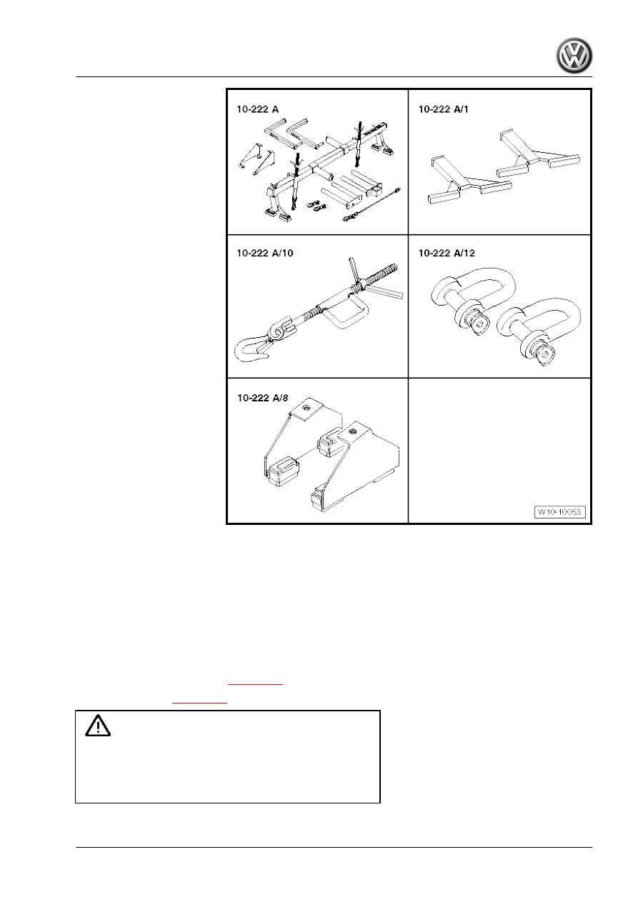
♦ Support - 10 - 222 A-
♦ 2x Hook - 10 - 222 A /10-
♦ Shackle - 10 - 222 A /12-
♦ Rack - 10 - 222 A /1-
Adjusting
Proceed as follows:
– Remove engine cover panel 

⇒ page 141

 .

– Remove air filter 

⇒ page 467

 .

Caution

Risk  of  irreparable  damage  to  electronic  components  when

disconnecting battery.

♦ Observe the necessary measures when disconnecting the

battery.

25
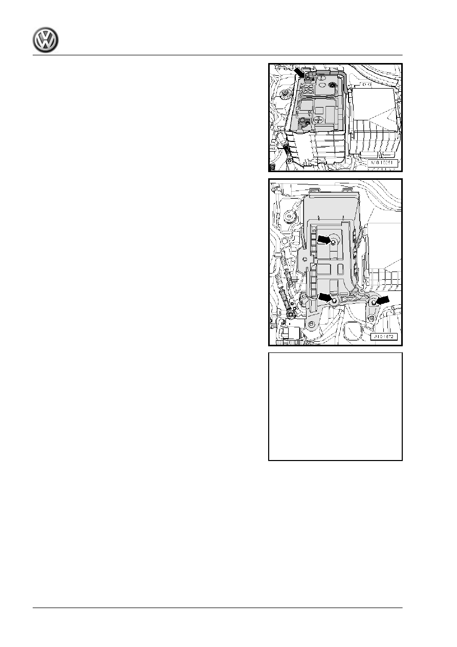
– Disconnect earth cable -arrow- from battery when ignition is

switched off.

– Remove battery ⇒  Rep. gr.  27 .

– Remove battery tray -arrows-.
– Fit support bracket - 10 - 222 A- , as shown, with the following

tool parts.

Passat:
♦ Rack - 10 - 222 A /1- , qty. 2
♦ 2x Hook - 10 - 222 A /10-
♦ Shackle - 10 - 222 A /12-

     Rep. gr.10 - Removing and installing engine

CC:
♦ Adapter - 10 - 222 A /8- , qty. 2
♦ 2x Hook - 10 - 222 A /10-
♦ Shackle - 10 - 222 A /12-

Note

The adapters - 10 - 222 A /8- must not be located on the screw

plates of the wings, as this will otherwise cause damage to

them.

The shackle - 10 - 222 A /12- is needed so the engine is raised

in its installation position and does not »fall back«.

All:
– Support engine with gearbox, but do not raise.

– Renew assembly mounting bolts -arrows- on engine side one

after the other (if not already carried out during engine instal‐

lation) and screw in hand-tight.

Vehicles with manual gearbox:
– Renew assembly mounting bolts -arrows- on gearbox side one

after the other (if not already carried out during engine instal‐

lation) and screw in hand-tight.

Vehicles with automatic gearbox
– Renew assembly mounting bolts -arrows- on gearbox side one

after the other (if not already carried out during engine instal‐

lation) and screw in hand-tight.

All:
– Slacken bolts on left and right-hand support arms by about two

turns each.

– Adjust assembly mounting and tighten securing bolts hand-

tight.

27

• There must be a distance -a- of at least 10 mm between engine

support and longitudinal member (right side).

• The side surface of the engine support -2- should be located

parallel to the support arm -1-.

Vehicles with manual gearbox:
• Ensure that edges of support arm (on gearbox side) -1- and

gearbox mounting -2- are parallel.

• Dimension -x- must be identical on both sides of mounting.

Vehicles with automatic gearbox:
• Ensure that edges of support arm (on gearbox side) -A- and

gearbox mounting -B- are parallel.

• Dimension -x- must be identical on both sides of mounting.
All:
– Tighten bolts for assembly mounting to required specified tor‐

que 

⇒ page 21

 .

Continue installation in reverse order of removal.

2.5

Adjusting assembly mountings (Golf,

Eos, Scirocco)

Note

If just the assembly mounting on the engine side is to be adjusted,

one hook - 10 - 222 A /10- will suffice on the engine side. There

is also no need to remove air filter, battery and battery carrier.

     Rep. gr.10 - Removing and installing engine

Special tools and workshop

equipment required

♦ Support - 10 - 222 A-
♦ 2x Hook - 10 - 222 A /10-
♦ Shackle - 10 - 222 A /12-
♦ Torque wrench - V.A.G 1331-
♦ Torque wrench - V.A.G 1332-
♦ Golf: Adapter - 10 - 222 A /13-

♦ Eos, Scirocco: Rack - 10 - 222 A /1-

29

Adjusting
Proceed as follows:
– Remove engine cover panel 

⇒ page 141

 .

– Remove air filter 

⇒ page 467

 .

– If fitted, remove charge air duct to sound generator

⇒ page 455

 .

Caution

Risk  of  irreparable  damage  to  electronic  components  when

disconnecting battery.

♦ Observe the necessary measures when disconnecting the

battery.

– Disconnect earth cable -arrow- from battery when ignition is

switched off.

– Remove battery ⇒  Rep. gr.  27 .

– Remove battery tray -arrows-.
– Fit support bracket - 10 - 222 A- with the following tool parts:

     Rep. gr.10 - Removing and installing engine

Golf:
♦ Adapter - 10 - 222 A /13- , qty. 2
♦ 2x Hook - 10 - 222 A /10-
♦ Shackle - 10 - 222 A /12- , qty. 2

Eos, Scirocco:
♦ Rack - 10 - 222 A /1- , qty. 2
♦ 2x Hook - 10 - 222 A /10-
♦ Shackle - 10 - 222 A /12-

Note

The rack feet - 10 - 222 A /1- must not be placed on the bolted

on sheet metal of the wings, or these might be damaged.

The shackle - 10 - 222 A /12- is needed so the engine is raised

in its installation position and does not »fall back«.

All:
– Support engine with gearbox, but do not raise.

– Renew assembly mounting bolts -arrows- on engine side one

after the other (if not already carried out during engine instal‐

lation) and screw in hand-tight.

Vehicles with manual gearbox:
– Renew assembly mounting bolts -arrows- on gearbox side one

after the other (if not already carried out during engine instal‐

lation) and screw in hand-tight.

31

Vehicles with automatic gearbox
– Renew assembly mounting bolts -arrows- on gearbox side one

after the other (if not already carried out during engine instal‐

lation) and screw in hand-tight.

All:
– Slacken bolts on left and right-hand support arms by about two

turns each.

– Adjust assembly mounting and screw in securing bolts hand-

tight.

• There must be a distance -a- of at least 10 mm between engine

support and longitudinal member (right side).

• The side surface of the engine support -2- should be located

parallel to the support arm -1-.

Vehicles with manual gearbox:
• Ensure that edges of support arm (on gearbox side) -1- and

gearbox mounting -2- are parallel.

• Dimension -x- must be identical on both sides of mounting.

Vehicles with automatic gearbox:
• Ensure that edges of support arm (on gearbox side) -A- and

gearbox mounting -B- are parallel.

• Dimension -x- must be identical on both sides of mounting.
All:
– Tighten bolts for assembly mounting to required specified tor‐

que 

⇒ page 21

 .

Continue installation in reverse order of removal.

2.6

Adjusting assembly mounting (Tiguan)

Special tools and workshop equipment required

     Rep. gr.10 - Removing and installing engine

♦ Support - 10-222A-

♦ Shackle - 10-222A/12-
♦ Adapter - 10-222A/16-
♦ Adapter - 10-222A/18-
♦ Adapter - 10-222A/22-
♦ Adapter - 10-222A/19-
♦ Square tube - T40091/1-

♦ Swivel joint - T40091/3-
Adjusting
Proceed as follows:
– Remove engine cover panel 

⇒ page 141

 .

– Remove air filter 

⇒ page 467

 .

Caution

Risk  of  irreparable  damage  to  electronic  components  when

disconnecting battery.

♦ Observe the necessary measures when disconnecting the

battery.

33

– Disconnect earth cable -arrow- from battery when ignition is

switched off.

– Remove battery ⇒  Rep. gr.  27 .

– Remove battery tray -arrows-.

– Fit support bracket - 10 - 222 A- as shown. The rear spindle is

not required. Attach hooks to support eyes on engine and

support engine and gearbox.

– Support engine with gearbox, but do not raise.

     Rep. gr.10 - Removing and installing engine

– Renew assembly mounting bolts -arrows- on engine side one

after the other (if not already carried out during engine instal‐

lation) and screw in hand-tight.

Vehicles with manual gearbox:
– Renew assembly mounting bolts -arrows- on gearbox side one

after the other (if not already carried out during engine instal‐

lation) and screw in hand-tight.

Vehicles with automatic gearbox:
– Renew assembly mounting bolts -arrows- in succession (if not

already carried out on installing engine) and screw in hand-

tight.

All:
– Slacken bolts on left and right-hand support arms by about two

turns each.

– Adjust assembly mounting and screw in securing bolts hand-

tight.

Assembly mounting on engine side:
• There must be a distance -a- of at least 10 mm between engine

support and longitudinal member (right side).

• The side surface of the engine support -2- should be located

parallel to the support arm -1-.

35

Assembly mounting on gearbox side:
• Ensure that edges of support arm (on gearbox side) -1- and

gearbox mounting -2- are parallel.

• Dimension -x- must be identical on both sides of mounting.
– Tighten bolts for assembly mounting to required specified tor‐

que 

⇒ page 23

 .

Continue installation in reverse order of removal.

     Rep. gr.10 - Removing and installing engine

13 – Crankshaft group

1

Cylinder block (pulley end)

Assembly overview - poly V-belt drive 

⇒ page 37

 .

Removing and installing poly V-belt 

⇒ page 39

Removing and installing tensioner for poly V-belt (Passat 2006 ▶,

CC) 

⇒ page 40

 .

Removing and installing tensioner for poly V-belt (Golf, Eos, Scir‐

occo) 

⇒ page 43

 .

Removing and installing tensioner for poly V-belt (Tiguan)

⇒ page 47

 .

Removing and installing bracket for ancillary units 

⇒ page 50

 .

Removing and installing vibration damper 

⇒ page 51

Renewing oil seal for vibration damper 

⇒ page 58

 .

1.1

Assembly overview - poly V-belt drive

1 - Vibration damper

❑ With poly V-belt pulley
❑ Removing and installing

⇒ page 51

2 - O-ring

❑ Renew

3 - Bolt

❑ Renew
❑ Removing and installing

⇒ page 51

❑ 150 Nm + 90° (

1

/4 turn)

further

❑ Use counterhold -

T10355- when loosen‐

ing and tightening

4 - Poly V-belt

❑ Check for wear
❑ Do not kink

Caution

Danger  of  destruction

due  to  reverse  running

direction in the case of a

poly  V-belt  that  has  al‐

ready run.

Before removing the poly

V-belt, use a piece of

chalk or a felt pen to mark

the running direction.

❑ Removing and installing

⇒ page 39

❑ When installing, make

sure it is properly seated on pulleys.

37

Volkswagen Technical Site:   http://vwts.ru   http://vwts.info

5 - Tensioning device for poly V-belt

❑ Swing with open-end spanner to slacken poly V-belt.
❑ Lock with locking pin - T10060 A- .
❑ Components of tensioner for poly V-belt 

⇒ page 38

❑ Removing and installing (Passat, CC) 

⇒ page 40

❑ Removing and installing (Golf, Eos, Scirocco) 

⇒ page 43

❑ Removing and installing (Tiguan) 

⇒ page 47

6 - Ancillary bracket

❑ With oil pressure switch - F1- , oil filter and engine oil cooler
❑ Removing and installing ancillary bracket 

⇒ page 50

 .

❑ Removing and installing engine oil cooler 

⇒ page 226

7 - Bolt

❑ 10 Nm

8 - Alternator

❑ Removing and installing ⇒  Rep. gr.  27

9 - Bolt

❑ 23 Nm

10 - Bolt

❑ Tightening sequence 

⇒ page 39

11 - Air conditioner compressor

❑ Do not unscrew or disconnect refrigerant lines
❑ Removing and installing ⇒  Rep. gr.  87

12 - Bolt

❑ 25 Nm

13 - Dowel sleeve

❑ For air conditioner compressor.

Components of tensioner for poly V-belt
1 - Tensioning roller, tighten securing bolt to 60 Nm
2 - Support element
3 - Ancillary bracket
4 - Centring sleeve
5 - Bolt

     Rep. gr.13 - Crankshaft group

Tightening sequence on bracket for ancillaries
– Fit ancillary bracket (start bolt -4- first).
– Tighten bolts in sequence -1 … 5- in 3 stages as follows:

1.

Tighten bolts by hand.

2.

Tighten bolts to 20 Nm.

3.

Turn bolts 90° (

1

/4 turn) further.

1.2

Removing and installing poly-V belt

Removing

Caution

Danger of destruction due to reverse running direction in the

case of a poly V-belt that has already run.

♦ Before removing the poly V-belt, use a piece of chalk or a

felt pen to mark the running direction.

– Remove noise insulation ⇒  General body repairs, exterior;

Rep. gr.  50 ; Noise insulation .

– Remove right air hose -arrows-.

39

– Turn tensioner in direction of -arrow- to relieve tension on poly

V-belt.

– Use the locking pin - T10060 A- to lock the tensioner.
– Remove poly V-belt.
Installing
Install in reverse order of removal, observing the following.

Note

Tighten alternator and air conditioner compressor mountings be‐

fore fitting poly V-belt.

– Fit poly V-belt onto crankshaft pulley first, then onto air condi‐

tioner compressor and alternator.

– Turn tensioner slightly with ring spanner and remove locking

pin - T10060 A- .

– Release tensioner.
– Check that poly V-belt is properly seated.
– Start engine and check that poly V-belt runs properly.

1.3

Removing and installing tensioner for poly V-belt (Passat 2006 ▶, CC)

     Rep. gr.13 - Crankshaft group

Special tools and workshop

equipment required


♦ Support - 10 - 222 A-
♦ 2x Hook - 10 - 222 A /10-
♦ Shackle - 10 - 222 A /12-
♦ Passat: frame - 10 - 222 A /1-
♦ CC: Adapter - 10 - 222 A /8-

♦ Locking pin - T10060 A-

41

Removing
Proceed as follows:
– Remove noise insulation ⇒  General body repairs, exterior;

Rep. gr.  50 ; Noise insulation .

– Remove front part of right wheel housing liner ⇒  General body

repairs, exterior; Rep. gr.  66 ; Wheel housing liner .

– First, undo bolt -1- and then bolts -2…3- and remove pendu‐

lum support.

– Remove bolt -2- at bracket for coolant pump for continued cir‐

culation - V51- .

Vehicles with auxiliary heater:
– Slacken clip -1- and remove bolt -2-.
– Detach exhaust silencer for auxiliary heater.
– Fit support bracket - 10 - 222 A- with the following tool parts:

Passat:
♦ Rack - 10 - 222 A /1- , qty. 2
♦ Hook - 10 - 222 A /10-

     Rep. gr.13 - Crankshaft group

CC:
♦ Adapter - 10 - 222 A /8- , qty. 2
♦ Hook - 10 - 222 A /10-
♦ Shackle - 10 - 222 A /12-

Note

The adapters - 10 - 222 A /8- must not be located on the screw

plates of the wings, as this will otherwise cause damage to

them.

The shackle - 10 - 222 A /12- is needed so the engine is raised

in its installation position and does not »fall back«.

All:
– Take up weight of engine with spindle.

– Unscrew bolts -arrows- of engine/gearbox support on the en‐

gine.

– Lower engine approx. 55 mm.
– Remove poly V-belt 

⇒ page 39

 .

– Move electrical wiring harness clear -arrow-.
– Remove bolt -1- and take off tensioning device for poly V-belt

from bracket for ancillaries.

Installing
• Specified torque 

⇒ page 37

 .

Install in reverse order of removal, observing the following.
– Insert tensioner -1- for poly V-belt in ancillary bracket -3- and

tighten bolt -5-.

• Note installation position of support element -2-: fit lug of sup‐

port element in hole on bracket for ancillaries.

• Note position of centring sleeve -4-.
– Adjust assembly mountings 

⇒ page 24

 .

1.4

Removing and installing tensioner for poly V-belt (Golf, Eos, Scirocco)

43

Special tools and workshop

equipment required

♦ Support - 10 - 222 A-
♦ Hook - 10 - 222 A /10-
♦ Shackle - 10 - 222 A /12-
♦ Locking pin - T10060 A-
♦ Torque wrench - V.A.G 1331-
♦ Golf: frame - 10 - 222 A /13-

♦ Eos, Scirocco: Rack - 10 - 222 A /1-

     Rep. gr.13 - Crankshaft group

Removing
Proceed as follows:
– If fitted, remove charge air duct to sound generator

⇒ page 455

 .

– Remove noise insulation ⇒  General body repairs, exterior;

Rep. gr.  50 ; Noise insulation .

– Remove front right wheel housing liner ⇒  General body re‐

pairs, exterior; Rep. gr.  66 ; Wheel housing liner .

– First, undo bolt -1- and then bolts -2…3- and remove pendu‐

lum support.

– Remove bolt -2- at bracket for coolant pump for continued cir‐

culation - V51- .

Vehicles with auxiliary heater:
– Slacken clip -1- and remove bolt -2-.
– Detach exhaust silencer for auxiliary heater.

45

Golf:
– Fit support bracket - 10 - 222 A- with the following tool parts:
♦ Rack - 10 - 222 A /13-
♦ Hook - 10 - 222 A /10-

Eos, Scirocco:
– Fit support bracket - 10 - 222 A- with the following tool parts:
♦ Rack - 10 - 222 A /1-
♦ Hook - 10 - 222 A /10-
♦ Shackle - 10 - 222 A /12-

Note

The rack feet - 10 - 222 A /1- must not be placed on the bolted

on sheet metal of the wings, or these might be damaged.

The shackle - 10 - 222 A /12- is needed so the engine is raised

in its installation position and does not »fall back«.

All:
– Take up weight of engine with spindle.
– Remove poly V-belt 

⇒ page 39

 .

– Unscrew bolts -arrows- of engine/gearbox support on the en‐

gine.

– Lower engine approx. 55 mm.

– Move electrical wiring harness clear -arrow-.
– Remove bolt -1- and take off tensioning device for poly V-belt

from bracket for ancillaries.

     Rep. gr.13 - Crankshaft group

Installing
• Specified torque 

⇒ page 37

 .

Install in reverse order of removal, observing the following.
– Insert tensioner -1- for poly V-belt in ancillary bracket -3- and

tighten bolt -5-.

• Note installation position of support element -2-: fit lug of sup‐

port element in hole on bracket for ancillaries.

• Note position of centring sleeve -4-.
– Adjust assembly mountings 

⇒ page 28

 .

1.5

Removing and installing tensioner for

poly V-belt (Tiguan)

Special tools and workshop equipment required
♦ Support - 10-222A-

♦ Shackle - 10-222A/12-
♦ Adapter - 10-222A/16-
♦ Adapter - 10-222A/18-
♦ Adapter - 10-222A/22-
♦ Adapter - 10-222A/19-
♦ Square tube - T40091/1-

♦ Swivel joint - T40091/3-
Removing
Proceed as follows:
– Remove noise insulation ⇒  General body repairs, exterior;

Rep. gr.  50 ; Noise insulation .

– Remove front right wheel housing liner ⇒  General body re‐

pairs, exterior; Rep. gr.  66 ; Wheel housing liner .

47

– First, undo bolt -1- and then bolts -2…3- and remove pendu‐

lum support.

Vehicles with all-wheel drive:
– Unscrew heat shield for flexible coupling.

– Mark position of propshaft with flexible coupling relative to

output shaft of bevel box.

– Unbolt propshaft -arrows- and pull off bevel box.

Counterhold at rear final drive when loosening or tightening prop‐

shaft.

     Rep. gr.13 - Crankshaft group

All:
– Remove bolt -2- at bracket for coolant pump for continued cir‐

culation - V51- .

Vehicles with auxiliary heater:
– Slacken clip -1- and remove bolt -2-.
– Detach exhaust silencer for auxiliary heater.
All:
– Remove engine cover panel 

⇒ page 141

 .

– Fit support bracket - 10 - 222 A- as shown. The rear spindle is

not required. Attach hooks to support eyes on engine and

support engine and gearbox.

– Take up weight of engine with spindle.

– Unscrew bolts -arrows- of engine/gearbox support on the en‐

gine.

– Lower engine approx. 55 mm.

– Remove poly V-belt 

⇒ page 39

 .

49

– Move electrical wiring harness clear -arrow-.
– Remove bolt -1- and take off tensioning device for poly V-belt

from bracket for ancillaries.

Installing
• Specified torque 

⇒ page 37

 .

Install in reverse order of removal, observing the following.
– Insert tensioner -1- for poly V-belt in ancillary bracket -3- and

tighten bolt -5-.

• Note installation position of support element -2-: fit lug of sup‐

port element in hole on bracket for ancillaries.

• Note position of centring sleeve -4-.
– Adjust assembly mountings 

⇒ page 32

 .

1.6

Removing and installing bracket for an‐

cillaries

Removing
Proceed as follows:
– Drain coolant 

⇒ page 241

 .

– Remove poly V-belt 

⇒ page 39

 .

– If fitted, remove charge air duct to sound generator

⇒ page 455

 .

– Remove alternator ⇒  Rep. gr.  27 .
– Remove electrical connector -1- for control valve for compres‐

sor of air-conditioning system - N280- .

WARNING

Danger of injury due to coolant.

♦ Do not open the air conditioner refrigerant circuit.

– Unscrew bolts -arrows- for air conditioning compressor.

Caution

Danger of damage to coolant lines and hoses.

♦ Do NOT stretch, kink or bend refrigerant lines and hoses.

– Fasten air-conditioning compressor together with connected

coolant hoses to the longitudinal member above.

     Rep. gr.13 - Crankshaft group

– Remove bolt -arrow- for dipstick guide tube.
– Unscrew bolts -1 … 5- and detach bracket for ancillary units

from coolant pump housing.

Installing

Note

If a further tightening angle is specified for certain bolts, these

must be renewed.

Renew O-rings and gaskets.

– Moisten O-rings -4- with coolant.
– Insert connecting piece -2- into coolant pump housing -3-.
– Push ancillary bracket -1- onto connecting piece -2-.

– Fit ancillary bracket (start bolt -4- first).
– Tighten bolts in sequence -1 … 5- in 3 stages as follows:

1.

Tighten bolts by hand.

2.

Tighten bolts to 20 Nm.

3.

Turn bolts 90° (

1

/4 turn) further.

The remaining installation steps are carried out in the reverse se‐

quence. Note the following:
♦ Specified torques 

⇒ page 37

 .

♦ Install A/C compressor ⇒  Rep. gr.  87 .
♦ Install alternator ⇒  Rep. gr.  27 .

1.7

Removing and installing vibration damp‐

er

Special tools and workshop equipment required

51

♦ Counter-hold tool - T10355-

♦ Assembly tool - T10531-

Components of assembly tool - T10531- :
♦ Support - T10531/1-
♦ Clamping pin - T10531/2-
♦ Turning over tool - T10531/3-
♦ Flange nut - T10531/4-

Note

The vibration damper securing bolt -A- is used to secure the vi‐

bration damper -1- and the timing chain sprocket -2- on crankshaft

-3-. Before unscrewing the securing bolt, lock the timing chain

sprocket in position relative to crankshaft as described below:

Removing:
– Remove noise insulation ⇒  General body repairs, exterior;

Rep. gr.  66 ; Noise insulation; Assembly overview - noise in‐

sulation .

– Remove right wheel housing liner ⇒  General body repairs,

exterior; Rep. gr.  66 ; Wheel housing liner; Removing and

installing wheel housing liner .

     Rep. gr.13 - Crankshaft group

Vehicles with auxiliary heater:
– Slacken clip -1- and remove bolt -2-.
– Detach exhaust silencer for auxiliary heater.

All:
– Unscrew bolts -arrows-.
– Remove air pipe (lift clips -items 1 and 2-).
– Remove poly V-belt 

⇒ page 39

 .

– Pull locking pin - T10060 A- out of tensioning device for poly

V-belt.

– Turn vibration damper to “TDC” position -arrow- using coun‐

terhold - T10355- .

• Notch on vibration damper must align with arrow marking on

cover for timing chains (bottom).

• The marking on the cover is located at »4 o'clock position«.

Caution

Initially, the vibration damper securing bolt must only be loos‐

ened by 

1

/2 turn.

– Loosen vibration damper bolt by 

1

/2 turn using counter hold

tool - T10355- .

– If vibration damper was turned while loosening bolt, reset TDC

position.

53

– Unscrew the 2 timing chain cover securing bolts -arrows-, as

shown in illustration. Bolts must be renewed.

– Fit support - T10531/1- to vibration damper, as shown in illus‐

tration, and tighten knurled screws -arrows- by hand.

– Unscrew vibration damper bolt completely.

– Check if turning over tool -A- slides easily over clamping

pieces -B-. If necessary, turn tensioning bolt -arrow-.

Note

Now, do not turn the tensioning bolt any more, or the clamping

pin - T10531/2- will be jammed when it is screwed into the crank‐

shaft.

– Screw clamping pin - T10531/2- into crankshaft, and tighten it

hand-tight with a 12 mm open-end spanner -A-.

     Rep. gr.13 - Crankshaft group

– Tighten tensioning bolt -A- hand-tight. This will lock the chain

sprocket in position relative to crankshaft.

– Unscrew knurled screws -arrows-. Remove support -

T10531/1- and vibration damper -A-.

Turning crankshaft without vibration damper
– Fit turning over tool -A- on clamping pin. Pay attention to tooth‐

ed contours of sprocket while doing so. In TDC position the

flat section of the tool faces upwards. Tighten turning over tool

with flange nut -B-.

– Crankshaft can now be turned on hexagon -arrow-.

55

Installing vibration damper
– If necessary, remove flange nut -B- and turning over tool -A-

from clamping pin.

– Fit vibration damper in TDC position. Pay attention to teeth of

chain sprocket -arrow- while doing so.

– Fit turning over tool -A- on clamping pin. The hexagon faces

towards vibration damper while doing so. Screw on flange nut

-B-. Move vibration damper slightly back and forth while doing

so, in order to ensure that vibration damper is properly seated

on teeth. Tighten flange nut, until vibration damper cannot be

turned any more.

– Fit support - T10531/1- to vibration damper, as shown in illus‐

tration, and tighten knurled screws -arrows- by hand.

     Rep. gr.13 - Crankshaft group


Content      ..      1      2      3      ..