Volkswagen 4-cyl. injection engine (1.8 and 2.0 l engine, chain drive). Manual (Edition 08.2018) - page 8
 

  Index      Manuals     Volkswagen 4-cyl. injection engine (1.8 and 2.0 l engine, chain drive). Manual (Edition 08.2018). Workshop Manual (Edition 08.2018)


Search            copyright infringement  


Content      ..     6      7      8      9     ..


Volkswagen 4-cyl. injection engine (1.8 and 2.0 l engine, chain drive). Manual (Edition 08.2018) - page 8


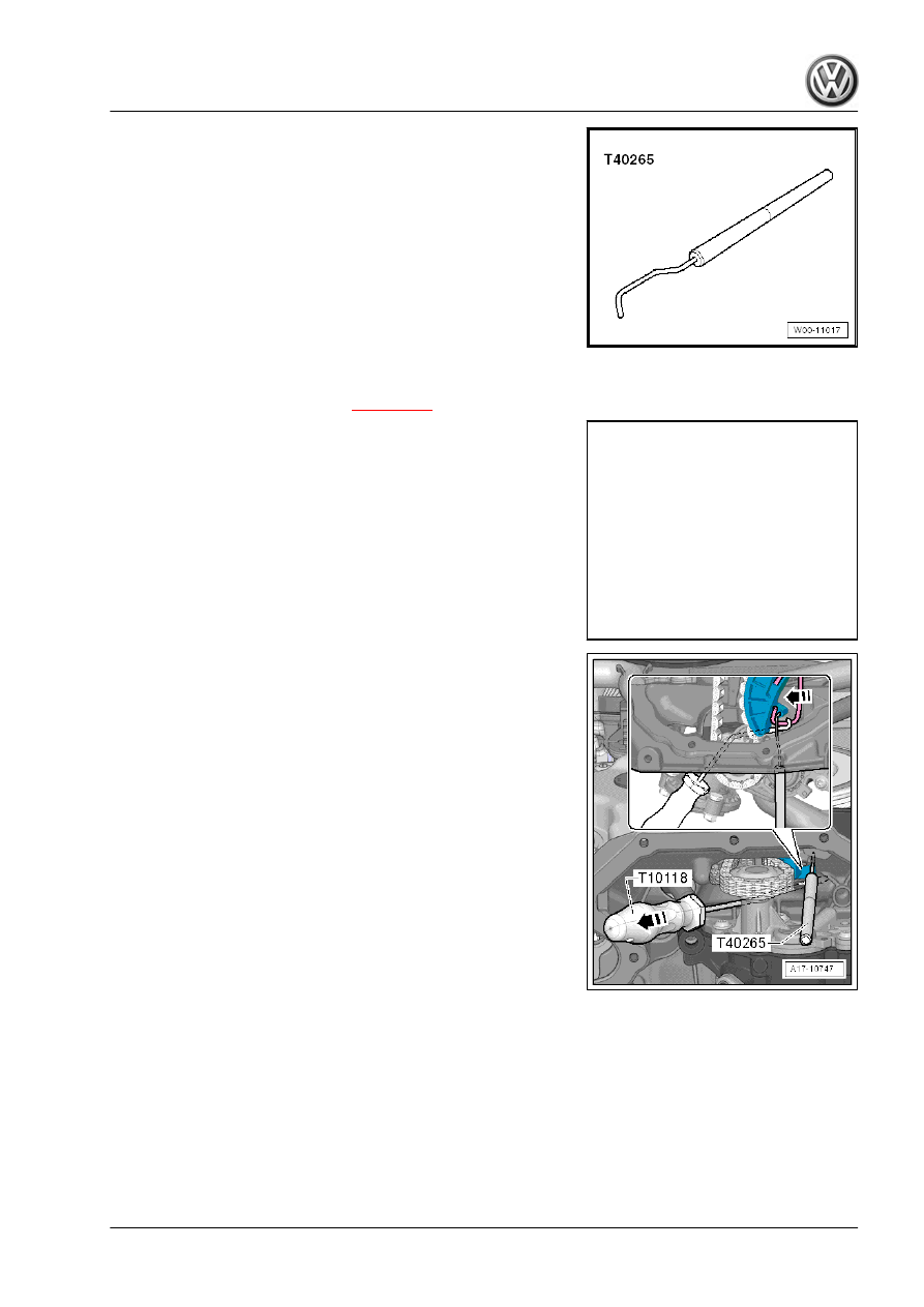
♦ Locking tool - T40265-

Removing:
– Remove sump (bottom section) 

⇒ page 213

 .

– Remove baffle plate -arrows-.

– Pull spring of chain tensioner in -direction of arrow- using as‐

sembly tool - T10118- and secure it with locking pin - T40265- .

217

– Unscrew bolts -arrows- and remove oil pump.
Engine codes CAWA, CAWB, CBFA, CCTA, CCTB, BZB, CGYA:

Engine codes CCZA, CCZB, CCZC, CCZD, CDAA, CDAB:
Installing:
– Check that both centring sleeves for centring oil pump are

present.

– Before installing oil pump, check strainer in oil suction pipe and

oil galleries in upper part of sump for soiling.

– Guide oil pump chain sprocket into drive chain and install oil

pump.

Caution

Risk of damage to engine.

♦ The following work step must be performed to ensure that

the chain tensioner spring jumps back to installation po‐

sition:

– Pull spring of chain tensioner in -direction of arrow- using as‐

sembly tool - T10118- and remove locking pin - T40265- .

Carry out the remaining installation in reverse sequence, noting

the following:
Specified torques

⇒ “1.1 Assembly overview - sump, oil pump”, page 210

 .

1.5

Removing and installing upper part of

sump

Special tools and workshop equipment required

     Rep. gr.17 - Lubrication

♦ Assembly tool - T10118-

♦ Locking tool - T40265-

♦ Silicone sealant ⇒  Electronic parts catalogue (ETKA)

Note

If the upper part of the sump is renewed, the baffle plate

⇒ Item 6 (page 211)

 must also be renewed.

Removing
– Remove gearbox ⇒  Rep. gr.  34 .
– Remove oil pump 

⇒ page 216

 .

– Remove sealing flange on gearbox side 

⇒ page 65

 .

– Remove front part of right wheel housing liner ⇒  General body

repairs, exterior; Rep. gr.  66 ; Wheel housing liner .

– Unscrew bolts -arrows-.
– Lift clips -1 and 2- and remove air pipe.

219

– Remove bolt -1-.
– Unscrew cable retainer next to continued coolant circulation

pump - V51- from upper part of sump.

– Unscrew bolts -arrows-.

DANGER!

Danger of injury! When removing upper part of sump, spring of

chain tensioner for oil pump drive jumps from upper part of

sump to lower timing chain cover. When removing upper part

of sump, do not grip between upper part of sump and lower

timing chain cover.

– Remove bolts -1 to 14- and lever off upper part of sump.

Caution

Lever off upper part of sump on gearbox side first. When lev‐

ering off, exercise caution to ensure the timing chain cover is

not bent in the process.

Installing
• Specified torque 

⇒ page 210

Note

Note expiry date of silicone sealant.

The sump (top section) must be installed within 5 minutes after

applying the silicone sealant.

– Remove sealant residue from cylinder block with a flat scraper.

WARNING

Risk of eye injury.

♦ Wear safety goggles.

     Rep. gr.17 - Lubrication

– Remove remaining sealant on sump (top section) and lower

timing chain cover e.g. using rotating plastic brush.

Note

Check timing chain cover for deformation. To do this, fit sump

upper part first without sealant and check gap between cover and

sump upper part. If deformation is evident and cover cannot be

aligned, renew cover after top section of sump has been installed.

– Clean sealing surfaces. They must be oil and grease free.
– Check oil passages in top section of sump and in crankcase

for soiling.

– Cut off nozzle on tube at front marking (∅ of nozzle approx. 3

mm).

Caution

Danger of lubrication system becoming clogged due to excess

sealant. Do not apply sealant bead thicker than specified.

– Apply silicone sealant onto clean sealing surface of upper part

of sump, as illustrated -arrow-.

– Apply some additional silicone sealant between cylinder block

and timing chain cover -arrows-.

• Thickness of sealant bead: 2 to 3 mm

Note

After applying the silicone sealant, the top part of the sump

must be fitted within 5 minutes.

The bead of sealant must not be thicker than specified, other‐

wise excess sealant can enter the sump and obstruct the

strainer in the oil intake pipe.

• Sump upper part and crankcase must be flush on gearbox

side.

221

– Fit upper part of sump straight away and tighten bolts

-1 to 14- in 3 stages as follows:

1 - Tighten bolts by hand.
2 - Tighten bolts to 15 Nm.
3 - Turn bolts 90° further.
– Install bolts -arrows-.
Specified torque for cover with 15 bolts 

⇒ page 90

Cover – tightening torque for version with 8 bolts 

⇒ page 90

Further assembly is basically a reverse of the dismantling se‐

quence.

1.6

Removing and installing oil pressure

control valve - N428- (engine codes

CCZA, CCZB, CCZC, CCZD, CDAA,

CDAB)

Special tools and workshop equipment required
♦ Used oil collector and extractor - V.A.G 1782-

Removing:
– Remove noise insulation ⇒  Rep. gr.  66 .
– Place used oil collection and extraction unit - V.A.G 1782- un‐

der engine.

     Rep. gr.17 - Lubrication

– Disconnect electrical connector -1-.
– Unscrew bolt -2- and pull off oil pressure control valve - N428-

-3-.

Installing:
• Specified torque 

⇒ Item 12 (page 211)

 .

Installation is carried out in the reverse order. When installing,

note the following:
♦ Renew O-ring.

223

2

Engine oil:

Oil capacities:
With oil filter, 4.7 l
Without oil filter 4.2 l
The oil capacity was determined experimentally. Due to toleran‐

ces, the oil temperature and the drip time, the actual oil capacity

may differ. The oil capacity also depends on the type of repair

work which has been performed. The correct oil level is indicated

by the marking on the dipstick.
Engine oil specifications ⇒ Maintenance ; Booklet  ; Service ta‐

bles .
Change engine oil ⇒ Maintenance ; Booklet  ; Engine oil: Drain or

extract; renew oil filter and replenish engine oil .
Check oil level:

Note

The oil level must not be above the max. mark - danger of damage

to catalytic converter!

Test conditions
• Engine oil temperature min. 60°C.
• Vehicle is level.
• Wait a few minutes after switching engine off to allow oil to flow

back into sump.

Test sequence
– Pull out dipstick, wipe off with a clean cloth and insert it again

to stop.

– Pull out dipstick again and read oil level.
Markings on dipstick:
a - Do not top up oil.
b - Oil may be replenished.
c - Oil must be added.

Note

The oil level must not be above the max. marking -arrow 1- and

not below the min. marking -arrow 2-.

     Rep. gr.17 - Lubrication

3

Oil filter, engine oil cooler and oil

pressure switch (engine codes CA‐

WA, CAWB, CBFA, CCTA, CCTB,

BZB, CGYA)

Assembly overview - oil filter, engine oil cooler and oil pressure

switch - F1- 

⇒ page 225

 .

Removing and installing engine oil cooler 

⇒ page 226

 .

Removing and installing coarse oil separator 

⇒ page 213

 .

Checking oil pressure and oil pressure switch 

⇒ page 227

Engine oil 

⇒ page 224

 .

3.1

Assembly overview - oil filter, engine oil cooler and oil pressure switch - F1-

1 - Ancillary bracket

❑ Removing and installing

⇒ page 50

2 - Oil pressure switch - F1-

❑ 1.4 bar - black
❑ Checking 

⇒ page 227

❑ 20 Nm
❑ Remove with articulated

wrench AF 24 - T40175-

3 - Seal

❑ Renew

4 - O-ring

❑ Renew

5 - O-ring

❑ Renew

6 - Valve unit
7 - Oil filter

❑ 22 Nm
❑ Remove and install with

oil filter tool - 3417- .

8 - Bolt

❑ 15 Nm

9 - Connection
10 - Seal

❑ Renew

11 - Engine oil cooler

❑ Observe notes

⇒ page 210

❑ Ensure clearance to ad‐

jacent components

❑ Connection diagram for coolant hoses 

⇒ page 238

❑ Removing and installing 

⇒ page 226

12 - Seal

❑ Renew

225

13 - Bolt

❑ Tightening sequence 

⇒ page 39

3.2

Removing and installing engine oil cool‐

er

Special tools and workshop equipment required
♦ Drip tray for workshop hoist - VAS 6208-

Removing
Proceed as follows:

WARNING

The cooling system is under pressure when the engine is hot!
Danger of scalding by steam and hot coolant.
Cover filler cap on expansion tank with a cloth and open care‐

fully to release pressure.

– Drain coolant 

⇒ page 241

 .

– Remove bracket for ancillaries 

⇒ page 50

 .

– Unscrew bolts -4 and 5- and remove engine oil cooler -3- to‐

gether with seal -2-.

Installing
Installation is carried out in the reverse order. When installing,

note the following:
• Specified torques 

⇒ page 225

Note

Renew gaskets and seals.

Secure all hose connections with the correct type of hose clips

(same as original equipment) ⇒  EKTA (Electronic parts cata‐

logue) .

     Rep. gr.17 - Lubrication

– Install engine oil cooler -3- with new seal -2-.

3.3

Checking oil pressure and oil pressure switch

Special tools and workshop

equipment required

♦ Oil pressure tester - V.A.G 1342-
♦ Voltage tester - V.A.G 1527B-
♦ Adapter set - V.A.G 1594C-
♦ Jointed wrench 24 mm - T40175-

227

Conditions:
• Engine oil level OK.
• Engine oil temperature at least 80 °C (radiator fan must have

run once)

Note

Functional check and repair of the optical and acoustic oil pres‐

sure display: Current flow diagrams ⇒ Vehicle diagnostic tester

“Function and component selection”.

Test sequence
• Specified torque 

⇒ Item 2 (page 225)

– Remove oil pressure switch - F1- and screw into tester.
– Screw tester into oil filter bracket in place of oil pressure

switch.

– Connect brown wire of tester to earth (-).
– Connect voltage tester - V.A.G 1527B- to battery positive (+)

and oil pressure switch using cables from auxiliary measuring

set - V.A.G 1594C- . LED must not light up.

– If the LED lights up, renew 1.4 bar oil pressure switch - F1- .
If LED does not light up:
– Start engine and increase engine speed. At 1.2 to 1.6 bar, the

LED must light up, otherwise renew oil pressure switch.

– Increase engine speed further.
• At 2000 rpm and an oil temperature of 80°C, the oil pressure

should be between 2.0 to 4.5 bar.

If specification is not attained:
– Check strainer in oil suction pipe for contamination/soiling

⇒ Item 22 (page 212)

 .

Note

Mechanical damage, e.g. to bearings, could also be the cause for

oil pressure being too low.

If no fault is found:
– Renew oil pump 

⇒ page 216

 .

If the specification is exceeded:
– Check oil channels.

     Rep. gr.17 - Lubrication

4

Oil filter, engine oil cooler and oil

pressure switch (engine codes

CCZA, CCZB, CCZC, CCZD, CDAA,

CDAB)

Assembly overview - oil filter, engine oil cooler 

⇒ page 229

 .

Removing and installing engine oil cooler 

⇒ page 230

 .

Removing and installing oil pressure switch - F1- 

⇒ page 231

 .

Removing and installing oil pressure switch for reduced oil pres‐

sure - F378- 

⇒ page 232

 .

Checking oil pressure and oil pressure switch 

⇒ page 233

Engine oil 

⇒ page 224

 .

4.1

Assembly overview - oil filter, engine oil cooler

1 - Ancillary bracket

❑ Removing and installing

⇒ page 50

2 - Oil pressure switch - F1-

❑ Blue insulation
❑ Removing and installing

⇒ page 231

❑ Checking 

⇒ page 233

❑ 20 Nm

3 - Oil pressure switch for re‐

duced oil pressure - F378-

❑ Brown insulation
❑ Removing and installing

⇒ page 232

❑ Checking 

⇒ page 233

❑ 20 Nm

4 - Seal

❑ Renew

5 - O-ring

❑ Not replacement part.

Include in items sup‐

plied with valve unit

6 - O-ring

❑ Not replacement part.

Include in items sup‐

plied with valve unit

7 - Valve unit

❑ With O-rings

8 - Oil filter

❑ Remove and install with

oil filter tool - 3417- .

9 - Bolt

❑ 15 Nm

229

10 - Connection
11 - Seal

❑ Renew

12 - Engine oil cooler

❑ Observe notes 

⇒ page 210

❑ Ensure clearance to adjacent components
❑ Removing and installing 

⇒ page 230

13 - Seal

❑ Renew

14 - Bolt

❑ Tightening sequence 

⇒ page 39

4.2

Removing and installing engine oil cool‐

er

Special tools and workshop equipment required
♦ Drip tray for workshop hoist - VAS 6208-

Removing

WARNING

The cooling system is under pressure when the engine is hot!
Danger of scalding by steam and hot coolant.
Cover filler cap on expansion tank with a cloth and open care‐

fully to release pressure.

– Drain coolant 

⇒ page 241

 .

– Remove bracket for ancillaries 

⇒ page 50

 .

     Rep. gr.17 - Lubrication

– Unscrew bolts -4 and 5- and remove engine oil cooler -3- to‐

gether with seal -2-.

Installing
Installation is carried out in the reverse order. When installing,

note the following:
• Specified torques

⇒ “4.1 Assembly overview - oil filter, engine oil cooler”,

page 229

 .

Note

Renew gaskets and seals.

Secure all hose connections with the correct type of hose clips

(same as original equipment) ⇒  EKTA (Electronic parts cata‐

logue) .

– Install engine oil cooler -3- with new seal -2-.
– Install bracket for ancillaries 

⇒ page 50

 .

– Add coolant 

⇒ page 241

 .

4.3

Removing and installing oil pressure

switch - F1-

Special tools and workshop equipment required
♦ Jointed wrench 24 mm - T40175-

231

Removing
– Only vehicles with sound generator: Open catch -1-, unclip fuel

lines -2- and loosen bolt -3- on activated charcoal filter. Place

charge air pipe to one side.

– Pull off breather line -1-, release activated charcoal filter -A-

and remove upwards -B-. Place activated charcoal filter to one

side.

Note

Place a cloth underneath bracket for ancillaries to catch any es‐

caping oil.

– Separate electrical connector -4- on oil pressure switch - F1- .
– Unscrew oil pressure switch -3-.
Installing
• Specified torque 

⇒ page 229

 .

Install in reverse order of removal, observing the following.
♦ Renew the seal.
♦ Insert new oil pressure switch immediately in hole to avoid loss

of oil.

♦ Check oil level.

4.4

Removing and installing oil pressure

switch for reduced oil pressure - F378-

Special tools and workshop equipment required
♦ Jointed wrench 24 mm - T40175-

     Rep. gr.17 - Lubrication

Removing
– Only vehicles with sound generator: Open catch -1-, unclip fuel

lines -2- and loosen bolt -3- on activated charcoal filter. Place

charge air pipe to one side.

– Pull off breather line -1-, release activated charcoal filter -A-

and remove upwards -B-. Place activated charcoal filter to one

side.

Note

Place a cloth underneath bracket for ancillaries to catch any es‐

caping oil.

– Separate electrical connector -2- on oil pressure switch for re‐

duced oil pressure - F378- .

– Unscrew oil pressure switch for reduced oil pressure - F378-

-1-.

Installing
• Specified torque 

⇒ page 229

 .

Install in reverse order of removal, observing the following.
♦ Renew the seal.
♦ Insert new oil pressure switch immediately in hole to avoid loss

of oil.

♦ Check oil level.

4.5

Checking oil pressure and oil pressure switch

233

Special tools and workshop

equipment required

♦ Oil pressure tester - V.A.G 1342-
♦ Voltage tester - V.A.G 1527B-
♦ Adapter set - V.A.G 1594C-
♦ Jointed wrench 24 mm - T40175-
Conditions:
• Engine oil level OK.
• Engine oil temperature at least 80 °C (radiator fan must have

run once)

Note

Functional check and repair of the optical and acoustic oil pres‐

sure display: Current flow diagrams ⇒ Vehicle diagnostic tester

“Function and component selection”.

     Rep. gr.17 - Lubrication

Checking oil pressure:
– Only vehicles with sound generator: Open catch -1-, unclip fuel

line -2- and loosen bolt -3- on activated charcoal filter. Place

charge air pipe to one side.

– Pull off breather line -1-, release activated charcoal filter -A-

and remove upwards -B-. Place activated charcoal filter to one

side.

Note

Place a cloth underneath bracket for ancillaries to catch any es‐

caping oil.

235

– Separate electrical connector -2- on oil pressure switch for re‐

duced oil pressure - F378- (brown).

– Unscrew oil pressure switch for reduced oil pressure - F378-

-1-.

– Screw oil pressure tester - V.A.G 1342- into oil filter bracket in

place of the oil pressure switch.

– Screw oil pressure switch for reduced oil pressure - F378- in

oil pressure tester - V.A.G 1342- .

– Reconnect charge air pipe and breather line for activated

charcoal filter.

– Start the engine.
• Oil pressure at idling speed: 0.85…2.1 bar.
• Oil pressure at 2000 rpm: 1.6…2.1 bar.
• Oil pressure at 3500 rpm: 3.0…4.0 bar.

Note

During the first 1000 km, the oil pressure at 2000 rpm can be

between 3.0 and 4.0 bar.

If specification is not attained:
– Check strainer in oil suction pipe for contamination/soiling

⇒ Item 22 (page 212)

 .

– Check oil pressure control valve - N428- ⇒ Vehicle diagnostic

tester.

Note

Mechanical damage, e.g. to bearings, could also be the cause for

oil pressure being too low.

If no fault is found:
– Renew oil pump 

⇒ page 216

 .

Check oil pressure switch for reduced oil pressure - F378-

(brown):
– Switch off engine.

     Rep. gr.17 - Lubrication

– Connect brown wire of tester to earth (-).
– Connect voltage tester - V.A.G 1527B- to battery positive (+)

and oil pressure switch for reduced oil pressure - F378-

(brown) using cables from auxiliary test set - V.A.G 1594C- .

• LED must not light up.
– If LED lights up, replace oil pressure switch for reduced oil

pressure - F378- .

If LED does not light up:
– Start engine. At 0.55 … 0.85 bar, the LED must light up; oth‐

erwise renew oil pressure switch.

Checking oil pressure switch - F1- (blue):
– Switch off engine.
– Connect voltage tester - V.A.G 1527B- to battery positive (+)

and oil pressure switch - F1- (blue) using cables from auxiliary

test set - V.A.G 1594C- .

• LED must not light up.
– If LED lights up, replace pressure switch - F1- .
If LED does not light up:
– Start engine and increase engine speed. At 2.15 to 2.95 bar,

the LED must light up, otherwise renew oil pressure switch.

237

19 – Cooling

1

Cooling system

WARNING

The cooling system is under pressure when the engine is hot!
Danger of scalding by steam and hot coolant.
Cover filler cap on expansion tank with a cloth and open care‐

fully to release pressure.

Note

Secure all hose connections with the correct type of hose clips

(same as original equipment) ⇒  EKTA (Electronic parts cata‐

logue) .

The arrow markings on coolant pipes and on ends of hoses

must align when installing.

Coolant hose schematic diagram 

⇒ page 238

Draining and filling with coolant 

⇒ page 241

 .

Checking cooling system for leaks 

⇒ page 246

 .

1.1

Coolant hose connection diagram

Note

Inclusion of auxiliary heater in coolant circuit ⇒  Rep. gr.  82

Vehicles with manual gearbox

     Rep. gr.19 - Cooling

1 - Radiator/cooler
2 - Continued coolant circula‐

tion pump - V51-
3 - Coolant pump
4 - Thermostat
5 - Engine oil cooler
6 - Cylinder head and cylinder

block
7 - Exhaust turbocharger
8 - Coolant expansion tank

❑ With cap
❑ Checking pressure re‐

lief valve in filler cap

⇒ page 246

 .

9 - To auxiliary heater
10 - From auxiliary heater
11 - Heat exchanger for heater
12 - Coolant connection

Vehicles with automatic gearbox

Note

Inclusion of auxiliary heater in coolant circuit ⇒  Rep. gr.  82

239

1 - Radiator/cooler
2 - Continued coolant circula‐

tion pump - V51-
3 - Thermostat
4 - Coolant pump
5 - Engine oil cooler
6 - Cylinder head and cylinder

block
7 - Exhaust turbocharger
8 - Coolant expansion tank

❑ With cap
❑ Checking pressure re‐

lief valve in filler cap

⇒ page 246

 .

9 - To auxiliary heater
10 - From auxiliary heater
11 - Heat exchanger for heater
12 - Gear oil cooler
13 - Coolant connection
14 - Thermostat for gear oil

cooler

❑ In some vehicles, the

thermostat is located on

the output side of the

gear oil cooler.

     Rep. gr.19 - Cooling

Volkswagen Technical Site:   http://vwts.ru   http://vwts.info

1.2

Draining and adding coolant

Special tools and workshop

equipment required

♦ Adapter for cooling system tester - V.A.G 1274/8-
♦ Drip tray for workshop hoist - VAS 6208-
♦ Spring-type clip pliers - VAS 6362-
♦ Coolant system charge unit - VAS 6096-
♦ Refractometer - T10007 A-
Draining

WARNING

The cooling system is under pressure when the engine is hot!
Danger of scalding by steam and hot coolant.
Cover filler cap on expansion tank with a cloth and open care‐

fully to release pressure.

– Open filler cap on expansion tank.

241

– Remove noise insulation ⇒  General body repairs, exterior;

Rep. gr.  50 ; Noise insulation .

Passat, CC, Golf, Scirocco and Eos:
– Remove air hose -items 1 and 2- and seal charge air cooler

with a clean cloth.

– Place drip tray - VAS 6208- beneath engine.

– Disconnect coolant hose -1- from bottom of radiator and drain

off coolant.

– Disconnect bottom coolant hose leading to continued coolant

circulation pump - V51- -arrow- and drain off coolant.

Tiguan:
– Remove bolt -2- at bracket for coolant pump for continued cir‐

culation - V51- .

Note

The continued circulation coolant pump - V51- remains installed.

     Rep. gr.19 - Cooling

– Pull off coolant hose -1-.

– Disconnect bottom coolant hose leading to continued coolant

circulation pump - V51- -arrow- and drain off coolant.

Vehicles with auxiliary heater:
– Disconnect coolant hoses -arrows- and drain off remaining

coolant.

Filling:

Caution

Use only distilled water for mixing coolant additives. The use

of distilled water ensures optimum protection against corro‐

sion.

243

Note

The water used for mixing has a major influence on the effec‐

tiveness of the coolant. Because the water quality differs from

country to country and even from region to region, the quality

of the water to be used in the cooling system has been speci‐

fied by Volkswagen. Distilled water fulfils all requirements.

Therefore, only ever use distilled water when mixing coolant

for topping up or renewing coolant.

Use only coolant additives which conform with the ⇒  Elec‐

tronic parts catalogue (ETKA) . Other coolant additives may

reduce corrosion protection substantially. The resulting dam‐

age could lead to loss of coolant and subsequent severe

damage to the engine.

Mixed in the proper proportions, coolant inhibits frost and cor‐

rosion damage as well as scaling. Such additives also raise

the boiling point of the coolant. For this reason, the cooling

system must be filled all-year-round with coolant additives.

Because of its high boiling point, the coolant improves engine

reliability under heavy loads, particularly in countries with trop‐

ical climates.

Use ONLY refractometer - T10007A- for determining current

anti-freeze value.

Frost protection must be guaranteed down to -25°C as a min‐

imum and, in countries with arctic conditions, down to approx.

-36°C. Increasing the frost protection is permissible only if cli‐

matic conditions require stronger frost protection. It may, how‐

ever, be increased only to a maximum of -48°C. Otherwise,

the cooling effect will be impaired.

Do not reduce the coolant concentration by adding water even

in warmer seasons and in warmer countries. Frost protection

must be guaranteed down to at least -25°C.

Read off anti-freeze figures for respective replenished coolant

additives.

The temperature read off the refractometer - T10007A- corre‐

sponds the »ice flocculation point«. Flakes of ice may start

forming in the coolant below this temperature.

Never reuse old coolant.

Use only a water/coolant additive mixture as a slip agent for

coolant hoses.

Recommended mixture ratios:

Frost

protection to

Anti-freeze

proportion

Coolant ad‐

ditive 

1)

Distilled wa‐

ter 

1)

-25 °C

-36 °C

40%

50%

3.2 l

4.0 l

4.8 l

4.0 l

1)

 The quantity of coolant can vary depending on the vehicle

equipment.

     Rep. gr.19 - Cooling

– Connect bottom coolant hose -1- to radiator.
– Install air pipe.

– Connect the coolant hose to the continued circulation coolant

pump - V51- -arrow-.

Vehicles with auxiliary heater:
– Connect coolant hoses -arrows-.
– Install noise insulation ⇒  General body repairs, exterior; Rep.

gr.  50 ; Noise insulation .

All:
With cooling system charge unit - VAS 6096- :
– Screw adapter for cooling system tester - V.A.G 1274/8- onto

expansion tank.

– Fill coolant circuit using cooling system charge unit -

VAS 6096- ⇒  Operating instructions for cooling system charge

unit VAS 6096.

Without cooling system charge unit - VAS 6096- :

– Slowly fill coolant to upper marking of shaded field on expan‐

sion tank.

– Fit expansion tank cap.
– Start engine and maintain an engine speed of about 2,000 rpm

for about 3 minutes.

– Run engine until radiator fan - V7- cuts-in.

WARNING

The cooling system is under pressure when the engine is hot!
Danger of scalding by steam and hot coolant.
Cover filler cap on expansion tank with a cloth and open care‐

fully to release pressure.

245

– Check coolant level and top up as needed. Once operating

temperature has been reached, the coolant level must be at

the upper mark; it should be in the middle of the shaded field

when the engine is cold.

1.3

Checking cooling system for leaks

Special tools and workshop

equipment required

♦ Adapter for cooling system tester - V.A.G 1274/8-
♦ Adapter for cooling system tester - V.A.G 1274/9-
♦ Cooling system tester - V.A.G 1274 B-

     Rep. gr.19 - Cooling

Note

To perform the leakage test correctly, first run a self-test on the

cooling system tester - V.A.G 1274 B- .

Self-test of cooling system tester - V.A.G 1274 B-
– Operate cooling system tester - V.A.G 1274 B- several times.

– Build up a pressure of 3.0 bar on cooling system tester .
– Observe pressure on pressure gauge of cooling system tester

for 30 seconds.

If no pressure builds up or if the pressure drops again:
The cooling system tester - V.A.G 1274 B- is leaking and should

not be used.

Checking cooling system for leaks
Prerequisites for check
• Engine at operating temperature.
Test sequence

WARNING

The cooling system is under pressure when the engine is hot!
Danger of scalding by steam and hot coolant.
Cover filler cap on expansion tank with a cloth and open care‐

fully to release pressure.

– Open filler cap -arrow- for coolant expansion tank.

247

– Fit cooling system tester - V.A.G 1274 B- with adapter -

V.A.G 1274/8- to coolant expansion tank.

– Build up pressure of approx. 1.5 bar using hand pump of cool‐

ing system tester.

• The pressure must not drop by more than 0.2 bar within 10 mi‐

nutes.

– If the pressure drops by more than 0.2 bar, locate and rectify

leaks.

Note

The pressure drop of 0.2 bar within 10 minutes depends on the

how far the coolant can cool down. The colder the engine, the

lower the pressure drop. If necessary, repeat the check while the

engine is cold.

DANGER!

Risk of scalding! Before disconnecting cooling system tester -

V.A.G  1274  B-  from  connecting  hose  or  connector  -  V.A.G

1274 B/1- , always relieve existing pressure. To do this, press

pressure relief valve on cooling system tester - V.A.G 1274 B-

until pressure gauge displays value of »0«.

Checking pressure relief valve in filler cap:
– Fit cooling system tester - V.A.G 1274 B- with adapter -

V.A.G 1274/9- onto coolant filler cap.

– Build up pressure using hand pump of cooling system tester.
• The pressure relief valve must open at a pressure of 1.4 to

1.6 bar.

     Rep. gr.19 - Cooling


Content      ..     6      7      8      9     ..