Toyota Land Cruiser Prado (2023 year). Manual in english - page 6
 

  Index      Manuals     Toyota Land Cruiser Prado (2023 year). Manual in english


Search            copyright infringement  


Content      ..     4      5      6      7     ..


Toyota Land Cruiser Prado (2023 year). Manual in english - page 6


95

1-2. Child safety

1

Fo
r s

a

fe

ty a
n

d se
cu

rity

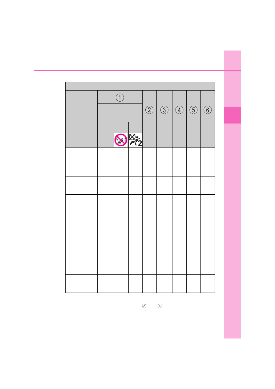
Detail information for child restraint systems installation

*

: All universal categories (group 0, 0+, I, II and III).

Toyota suggests the users to use   and   seating positions.

Seating position

Seat position 

number

With-

out 
air-

bag 

man-

ual 

on-off 

switch

Airbag man-

ual on-off 

switch

ON

OFF

Left Center Right

Left

Right

Seating posi-
tion suitable
for universal
belted (Yes/
No)

*

Yes

For-

ward-

facing 

only

Yes

For-

ward-

facing 

only

Yes

No

No

No

No

No

i-Size seating
position (Yes/
No)

No

No

No

No

No

No

No

No

Seating posi-
tion suitable
for lateral fix-
ture (L1/L2/
No)

No

No

No

No

No

No

No

No

Suitable rear-
ward facing
fixture (R1/
R2X/R2/R3/
No)

No

No

No

No

No

No

No

No

Suitable for-
ward facing
fixture (F2X/
F2/F3/No)

No

No

No

F2X, 

F2, 

F3

No

F2X, 

F2, 

F3

No

No

Suitable junior
seat fixture
(B2/B3/No)

No

No

No

B2, 

B3

No

B2, 

B3

No

No

96

1-2. Child safety

ISOFIX child restraint systems are divided into different “fixture”.
The child restraint system can be used in the seating positions for
“fixture” mentioned in the table above. For kind of “fixture” relation,
confirm the following table.
If your child restraint system has no kind of “fixture” (or if you can-
not find information in the table below), please refer to the child
restraint system “vehicle list” for compatibility information or ask the
retailer of your child seat.

Mass 

groups

Child weight

Size 

class

Fixture

Description

0

up to 10 kg 

(22 lb.)

E

R1

Rearward-facing infant seat

F

L1

Left lateral-facing infant seat 

(Carrycot)

G

L2

Right lateral-facing infant seat 

(Carrycot)

0+

up to 13 kg 

(28 lb.)

C

R3

Full-size, rearward-facing child 

restraint system

D

R2

Reduced-size, rearward-facing 

child restraint system

R2X

Reduced-size, rearward-facing 

child restraint system

E

R1

Rearward-facing infant seat

I

9 to 18 kg 

(20 to 39 lb.)

A

F3

Full-height, forward-facing child 

restraint system

B

F2

Reduced-height, forward-facing 

child restraint system

B1

F2X

Reduced-height, forward-facing 

child restraint system

C

R3

Full-size, rearward-facing child 

restraint system

D

R2

Reduced-size, rearward-facing 

child restraint system

II

15 to 25 kg 

(34 to 55 lb.)

B2, B3

Junior seat

III

22 to 36 kg 

(48 to 79 lb.)

97

1-2. Child safety

1

Fo
r s

a

fe

ty a
n

d se
cu

rity

Recommended child restraint systems information

The child restraint systems mentioned in the table may not be avail-
able outside the EU countries and United Kingdom.

Recommended 

child restraint sys-

tem

Size

Direction of travel

Fixation

fixed with 

lower 

anchorages

fixed 

with a 

seat belt

MAXI COSI CAB-

RIOFIX

Up to 13 kg

(Up to 28 lb.)

Rearward-facing 

use only

Not appli-

cable

Yes

TOYOTA MAXI 

PLUS

15 to 36kg

(34 to 79 lb.)

Forward-facing 

use only

Yes

No

98

1-2. Child safety

Confirm with the operation manual enclosed with the child restraint
system about the installation of the child restraint system.

Child restraint system installation method

Installation method

Page

Seat belt attach-

ment

P. 99

ISOFIX lower 

anchorage attach-

ment

P. 102

Top tether anchor-

age attachment

P. 104

99

1-2. Child safety

1

Fo
r s

a

fe

ty a
n

d se
cu

rity

Installing child restraint system using a seat belt

Install the child restraint system in accordance to the operation
manual enclosed with the child restraint system.
If the child restraint system on hand is not within the “universal” cat-
egory (or the necessary information is not in the table), refer to the
“Vehicle List” provided by the child restraint system maker for vari-
ous possible installation positions, or check the compatibility after
asking the retailer of the child restraint system. (

P. 67, 68, 73, 80,

86, 92)

If installing the child restraint system to the front passenger seat
is unavoidable, refer to P. 63 for front passenger seat adjustment.
Fold the seatback forward. Then return the seatback and secure
it at the 1st lock position (most upright position). (

P. 198)

If the head restraint interferes with the child restraint system
installation and the head restraint can be removed, remove the
head restraint. Otherwise, put the head restraint in the upper
most position. (

P. 216)

Run the seat belt through the
child restraint system and
insert the plate into the
buckle. Make sure that the
belt is not twisted. Securely
fix the seat belt to the child
restraint system in accor-
dance to the directions

Child restraint system fixed with a seat belt

1

2

3-door models

5-door models

3

4

100

1-2. Child safety

enclosed with the child
restraint system.

If your child restraint system
is not equipped with a lock-
off (a seat belt locking fea-
ture), secure the child
restraint system using a lock-
ing clip.

After installing the child restraint system, rock it back and forth to
ensure that it is installed securely. (

P. 101)

Removing a child restraint system installed with a seat belt

Press the buckle release button and fully retract the seat belt.

When releasing the buckle, the child restraint system may spring up due
to the rebound of the seat cushion. Release the buckle while holding
down the child restraint system.
Since the seat belt automatically reels itself, slowly return it to the stow-
ing position.

When installing a child restraint system

You may need a locking clip to install the child restraint system. Follow the
instructions provided by the manufacturer of the system. If your child restraint
system does not provide a locking clip, you can purchase the following item
from any authorized Toyota retailer or Toyota authorized repairer, or any reli-
able repairer: Locking clip for child restraint system 
(Part No. 73119-22010)

5

6

101

1-2. Child safety

1

Fo
r s

a

fe

ty a
n

d se
cu

rity

WARNING

When installing a child restraint system

Observe the following precautions.
Failure to do so may result in death or serious injury.

Do not allow children to play with the seat belt. If the seat belt becomes
twisted around a child’s neck, it may lead to choking or other serious inju-
ries that could result in death. If this occurs and the buckle cannot be
unfastened, scissors should be used to cut the belt.

Ensure that the belt and plate are securely locked and the seat belt is not
twisted.

Shake the child restraint system left and right, and forward and backward
to ensure that it has been securely installed.

After securing a child restraint system, never adjust the seat.

When a junior seat is installed, always ensure that the shoulder belt is
positioned across the center of the child’s shoulder. The belt should be
kept away from the child’s neck, but not so that it could fall off the child’s
shoulder.

Follow all installation instructions provided by the child restraint system
manufacturer.

102

1-2. Child safety

ISOFIX lower anchorages (ISOFIX child restraint system)

Lower anchorages are provided
for the outboard second seats.
(Tags displaying the location of
the anchorages are attached to
the seats.)

Installation with ISOFIX lower anchorage (ISOFIX child
restraint system)

Install the child restraint system in accordance to the operation
manual enclosed with the child restraint system.
If the child restraint system on hand is not within the “universal” cat-
egory (or the necessary information is not in the table), refer to the
“Vehicle List” provided by the child restraint system maker for vari-
ous possible installation positions, or check the compatibility after
asking the retailer of the child restraint system. (

P. 67, 68, 73, 80,

86, 92)

Fold the seatback forward. Then return the seatback and secure
it at the 1st lock position (most upright position). (

P. 198)

If the head restraint interferes with the child restraint system
installation and the head restraint can be removed, remove the
head restraint. Otherwise, put the head restraint in the upper
most position. (

P. 216)

Child restraint system fixed with an ISOFIX lower anchorage

1

3-door models

5-door models

2

103

1-2. Child safety

1

Fo
r s

a

fe

ty a
n

d se
cu

rity

Flip the cover (3-door models
and 5-door models with third
power/manual seats), and
install the child restraint sys-
tem to the seat.

The bars are installed in the
clearance between the seat
cushion and seatback.

After installing the child restraint system, rock it back and forth to
ensure that it is installed securely. (

P. 101)

3

WARNING

When installing a child restraint system

Observe the following precautions.
Failure to do so may result in death or serious injury.

After securing a child restraint system, never adjust the seat.

When using the lower anchorages, be sure that there are no foreign
objects around the anchorages and that the seat belt is not caught behind
the child restraint system.

Follow all installation instructions provided by the child restraint system
manufacturer.

4

104

1-2. Child safety

Top tether anchorages

Top tether anchorages are pro-
vided for each second seat.
Use top tether anchorages
when fixing the top strap.

Fixing the top strap to the top tether anchorage

Install the child restraint system in accordance to the operation
manual enclosed with the child restraint system.

Adjust the head restraint to
the upmost position.

If the head restraint interferes
with the child restraint system or
top strap installation and the
head restraint can be removed,
remove the head restraint. 
(

P. 216)

Open the anchor bracket
cover, latch the hook onto the
anchor bracket and tighten
the top strap.

Make sure the top strap is
securely latched. (

P. 101)

When installing the child
restraint system with the head
restraint being raised, be sure to
have the top strap pass under-
neath the head restraint.

Using a top tether anchorage

Top tether 
anchorages

Top strap

1

Hook

Top strap

2

105

1-2. Child safety

1

Fo
r s

a

fe

ty a
n

d se
cu

rity

WARNING

When installing a child restraint system

Observe the following precautions.
Failure to do so may result in death or serious injury.

Firmly attach the top strap and make sure that the belt is not twisted.

Do not attach the top strap to anything other than the top tether anchor-
age.

After securing a child restraint system, never adjust the seat.

Follow all installation instructions provided by the child restraint system
manufacturer.

When installing the child restraint system with the head restraint being
raised, after the head restraint has been raised and then the top tether
anchorage has been fixed, do not lower the head restraint. 

NOTICE

Top tether anchorages

When not in use, make certain to close the lid. If it remains open, the lid
may be damaged.

106

1-3. Emergency assistance

ERA-GLONASS/EVAK

1, 2, 3

Microphone
“SOS” button

*

Indicator lights

*

: This button is intended for commu-

nication with the ERA-GLONASS/
EVAK system operator.
Other SOS buttons available in
other systems of a motor vehicle
do not relate to the device and are
not intended for communication
with the ERA-GLONASS/EVAK
system operator.

1

: If equipped

2

: Operates within regions offering emergency notification services. Ask any authorized

Toyota retailer or Toyota authorized repairer, or any reliable repairer for details.

3

: The system name differs depending on the country.

The Emergency Call system is a device installed on a vehicle to
determine its location and movement direction (using GLONASS
[Global Navigation Satellite System] and GPS [Global Position-
ing System] signals), and ensure the generation and transmis-
sion of vehicle information (in a nonadjustable form) in case of
traffic accidents or other incidents on motor roads in the coun-
tries offering emergency notification services. In addition, it
ensures two-way voice communication between the vehicle and
an ERA-GLONASS/EVAK system operator through cellular net-
works (GSM).
Automatic Emergency Calls (via Automatic Collision Notifica-
tion) and manual Emergency Calls (by pressing the “SOS” but-
ton) can be made to the ERA-GLONASS/EVAK control center.
This service is mandatory according to the technical regulations
of the Customs Union.

System components

1
2
3

107

1-3. Emergency assistance

1

Fo
r s

a

fe

ty a
n

d se
cu

rity

Automatic Emergency Calls

If any airbag deploys, the system is designed to automatically call
the ERA-GLONASS/EVAK control center.

*

 The answering operator

receives the vehicle’s location, the time of the incident and the vehi-
cle VIN, and attempts to speak with the vehicle occupants to
assess the situation. If the occupants are unable to communicate,
the operator automatically treats the call as an emergency and con-
tacts the nearest emergency services provider (112 system etc.) to
describe the situation and request that assistance be sent to the
location.

*

: In some cases, the call cannot be made. (

P. 109)

Manual Emergency Calls

In the event of an emergency, press the “SOS” button to call the
ERA-GLONASS/EVAK control center.* The answering operator will
determine your vehicle’s location, assess the situation, and dis-
patch the necessary assistance required.

If you accidentally press the “SOS” button, tell the operator that you are
not experiencing an emergency.

*

: In some cases, the call cannot be made. (

P. 109)

Emergency Notification Services

108

1-3. Emergency assistance

When the engine switch is turned to the “ON” position (vehicles with-
out smart entry & start system) or IGNITION ON mode (vehicles with
smart entry & start system), the red indicator light will illuminate for 10
seconds and then the green indicator light will illuminate, indicating
that the system is enabled. The indicator lights indicate the following:

If the green indicator light illuminates and stays on, the system is
enabled.

If the green indicator light flashes twice per second, an automatic or
manual Emergency Call is being made.

If no indicator lights illuminate, the system is not enabled.

If the red indicator light illuminates at any time other than immedi-
ately after the engine switch is turned to the “ON” position (vehicles
without smart entry & start system) or IGNITION ON mode (vehi-
cles with smart entry & start system), the system may be malfunc-
tioning or the backup battery may be depleted. The backup battery
has lifespan of at least 3 years. Contact any authorized Toyota
retailer or Toyota authorized repairer, or any reliable repairer.

If the red indicator light blinks for approximately 30 seconds during
an Emergency Call, the call has been disconnected or the cellular
network signal is weak.

Free/Open Source Software Information

This product contains Free/Open Source Software (FOSS).
The license information and/or the source code of such FOSS can be found
at the following URL.
http://www.opensourceautomotive.com/dcm/toyota/

A test mode is provided for to check the performance of the Emer-
gency Call system. To test the device, contact any authorized Toyota
retailer or Toyota authorized repairer, or any reliable repairer.

Indicator lights

Device test mode

109

1-3. Emergency assistance

1

Fo
r s

a

fe

ty a
n

d se
cu

rity

WARNING

When the Emergency Call may not be made

It may not be possible to make Emergency Calls in any of the following sit-
uations. In such cases, report to emergency services provider (112 system
etc.) by other means such as nearby public phones.
• Even when the vehicle is in the cellular phone service area, it may be

difficult to connect to the ERA-GLONASS/EVAK control center if the
reception is poor or the line is busy. In such cases, even though the sys-
tem attempts to connect to the ERA-GLONASS/EVAK control center,
you may not be able to connect to the ERA-GLONASS/EVAK control
center to make Emergency Calls and contact emergency services.

• When the vehicle is out of the cellular phone service area, the Emer-

gency Calls cannot be made.

• When any related equipment (such as the “SOS” button panel, indicator

lights, microphone, speaker, DCM, antenna, or any wires connecting
the equipment) is malfunctioning, damaged or broken, the Emergency
Call cannot be made.

• During an Emergency Call, the system makes repeated attempts to

connect to the ERA-GLONASS/EVAK control center. However, if it can-
not connect to the ERA-GLONASS/EVAK control center due to poor
radio wave reception, the system may not be able to connect to the cel-
lular network and the call may finish without connecting. The red indica-
tor light will blink for approximately 30 seconds to indicate this
disconnection.

• This device may not function if a shock is applied to it.

If the battery’s voltage decreases or there is a disconnection, the system
may not be able to connect to the ERA-GLONASS/EVAK control center.

When the Emergency Call system is replaced with a new one

The Emergency Call system should be registered. Contact any authorized
Toyota retailer or Toyota authorized repairer, or any reliable repairer.

110

1-3. Emergency assistance

WARNING

For your safety

Please drive safely.
The function of this system is to assist you in making the Emergency Call
in case of accidents such as traffic accidents or sudden medical emergen-
cies, and it does not protect the driver or passengers in any way. Please
drive safely and fasten your seatbelts at all times for your safety.

In case of an emergency, make lives the top priority.

If you smell anything burning or other unusual smells, leave the vehicle
and evacuate to a safe area immediately.

Since the system detects shocks, the automatic reporting may not always
occur synchronized with the operation of the airbag system. (If the vehicle
is struck from behind, etc.)

For safety, do not make the Emergency Call while driving.
Making calls during driving may cause mishandling of the steering wheel,
which may lead to unexpected accidents.
Stop the vehicle and confirm the safety of your surroundings before mak-
ing the Emergency Call.

When changing fuses, please use the specified fuses. Using other fuses
may cause ignition or smoke in the circuit and lead to a fire.

Using the system while there is smoke or an unusual smell may cause a
fire. Stop using the system immediately and consult any authorized Toyota
retailer or Toyota authorized repairer, or any reliable repairer.

NOTICE

To prevent damage

Do not pour any liquids onto the “SOS” button panel, etc. and do not impact
it.

If the “SOS” button panel, speaker or microphone malfunctions during
an Emergency Call or manual maintenance check

It may not be possible to make Emergency Calls, confirm the system status,
or communicate with the ERA-GLONASS/EVAK control center operator. If
any of the above equipment is damaged, please consult any authorized
Toyota retailer, Toyota authorized repairer, or any reliable repairer.


Content      ..     4      5      6      7     ..