Toyota Supra (2023 year). Manual in english - page 15
 

  Index      Toyota     Toyota Supra (2023 year). Manual in english


Search            copyright infringement  


Content      ..     13      14      15      16     ..


Toyota Supra (2023 year). Manual in english - page 15


233

3-1. CONTROLS

3

CON

T

ROLS

This chapter describes all stan-
dard, country-specific and 
optional features offered with 
the series. It also describes fea-
tures and functions that are not 
necessarily available in your 
vehicle, e.g., due to the selected 
options or country versions. This 
also applies to safety-related 
functions and systems. When 
using these functions and sys-
tems, the applicable laws and 
regulations must be observed.

The air quality in the vehicle is 
improved by the following com-
ponents:

Emission tested car's interior.

Microfilter.

Air conditioning system to 
control the temperature, air 
flow and recirculated-air 
mode.

Automatic recirculated-air 
control AUC.

Parked-car ventilation.

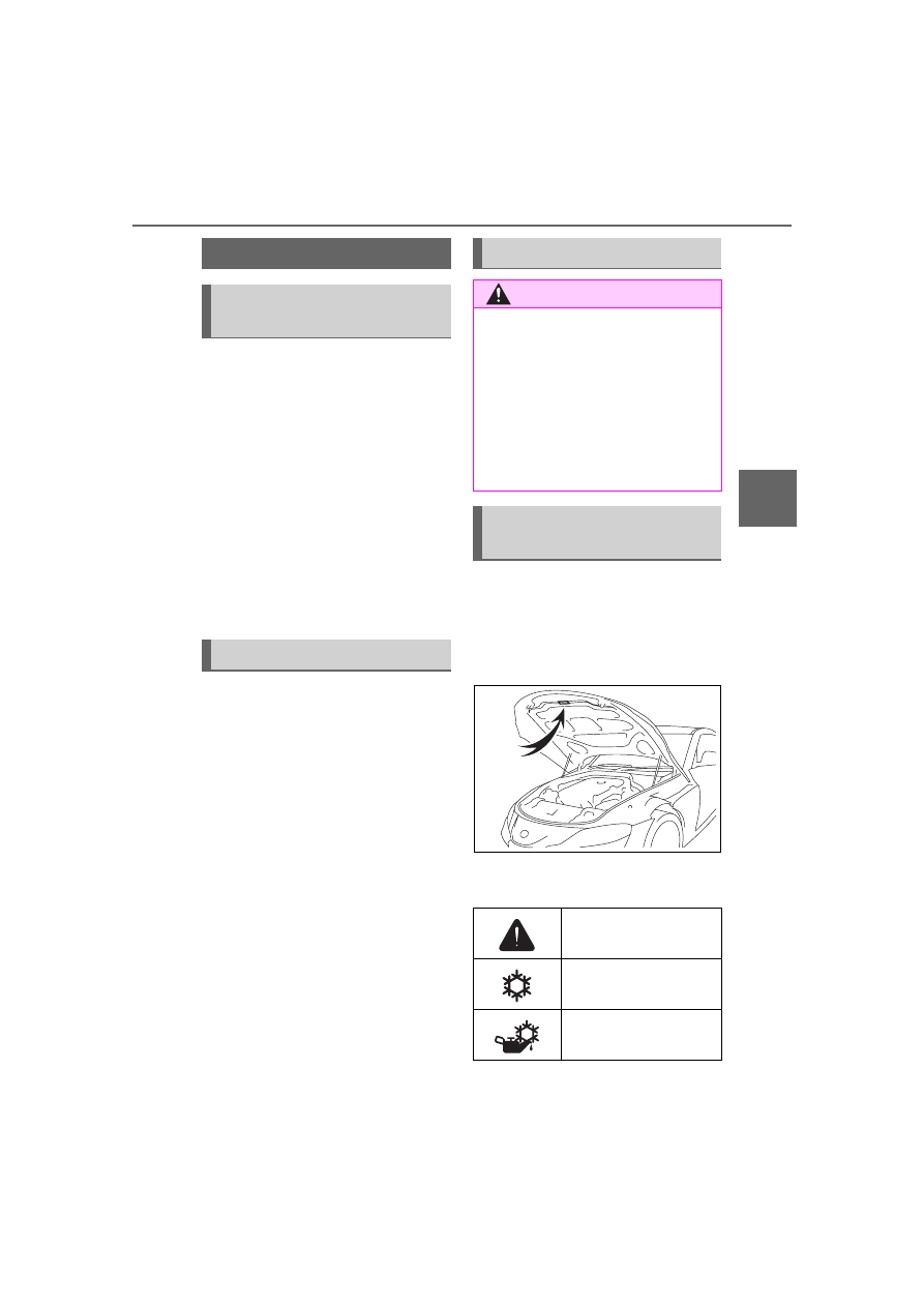
A label regarding the refriger-
ant of the air conditioning sys-
tem is attached to the hood at 
the location shown in the fol-
lowing illustration.

The meaning of each symbol 
on the label are as follows:

Climate control

Vehicle features and 
options

Interior air quality

Safety notes

WARNING

When using the air conditioning 

system, seat heaters, etc. for a 

long period of time, make sure 

that no body parts are kept near 

the air outlets or in direct contact 

with the seat, as doing so may 

lead to minor burns or chill burns. 

If you feel unusual while using the 

air conditioning system or seat 

heaters, stop use or change the 

setting immediately.

Air conditioning system 
refrigerant

Caution

Air conditioning sys-
tem

Air conditioning sys-
tem lubricant type

234

3-1. CONTROLS

Requires registered 
technician to service 
air conditioning sys-
tem

Flammable refrigerant

NOTICE

When repairing/replacing 

parts of the air conditioning 

system

Have repair/replacement per-

formed by your Toyota dealer.

When a part of the air conditioning 

system, such as the evaporator, is 

to be replaced, it must be 

replaced with a new one.

Automatic air condition-
ing

Overview

Buttons in the vehicle

Climate control functions

Button

Function

Temperature, refer to 
page 236.

Air-conditioning mode, 
refer to page 236.

Maximum cooling, refer 
to page 237.

AUTO program, refer to 
page 237.

Recirculated-air mode, 
refer to page 238.

Switch off, refer to page 
236.

Air distribution, man-
ual, refer to page 239.

Defrost and defog the 
windshield, refer to 
page 239.

Rear window defroster, 
refer to page 239.

235

3-1. CONTROLS

3

CON

T

ROLS

Press any button except for the 
following:

Switching off.

Rear window defroster.

Seat heating.

Complete system:

The automatic air conditioning 
achieves the set temperature as 
quickly as possible, if needed, 
by using the maximum cooling 
or heating capacity, and then 
keeps it constant.

Via Toyota Supra Command:

1

"My Vehicle"

2

"Vehicle settings"

3

"Climate functions"

4

"Temperature adjustment, 
upper body"

5

Set the desired temperature.

Do not rapidly switch between 
different temperature settings. 
Otherwise, the automatic air 
conditioning will not have suffi-
cient time to adjust the set tem-
perature.

The air in the car's interior will 
be cooled and dehumidified 
and, depending on the tempera-
ture setting, warmed again.
The car's interior can only be 
cooled with the drive-ready state 
switched on.

Seat heating, refer to 
page 113.

Air flow, manual, refer 
to page 238.

Switching on/off

Switching on

Switching off

Press and hold the but-
ton.

Temperature

Concept

Button

Function

Adjusting

Turn the dial clockwise 
to increase the tempera-
ture and counterclock-
wise to decrease the 
temperature.

Air conditioning

Concept

236

3-1. CONTROLS

Air conditioning is switched on 
with the engine running.
Depending on the weather, the 
windshield and side windows 
may fog up briefly when 
drive-ready state is switched on.
The air conditioning is switched 
on automatically with the AUTO 
program.
When using the automatic air 
conditioning, condensation 
water develops and collects 
underneath the vehicle.

The system is set to the lowest 
temperature, optimum air flow 
and recirculated-air mode with 
the drive-ready state switched 
on.

The function is available with 
external temperatures above 
approx. 32 °F/0 °C and with the 
drive-ready state switched on.

The LED is illuminated with the 
system switched on.
Air flows out of the vents to the 
upper body region. The vents 
need to be open for this.
The air flow can be adjusted 
with the program active.

The AUTO program cools, venti-
lates or heats the car's interior 
automatically.
The air flow, air distribution and 
temperature will be controlled 
automatically depending on the 
interior temperature and the set-
ting for the desired temperature.

The LED is illuminated with the 
AUTO program switched on.
Depending on the selected tem-
perature and outside influ-
ences, the air is directed to the 
windshield, side windows, upper 

Switching on/off

Press the button.

Maximum cooling

Concept

General information

Switching on/off

Press the button.

AUTO program

Concept

Switching on/off

Press the button.

237

3-1. CONTROLS

3

CON

T

ROLS

body, and into the floor area.
The air conditioning, refer to 
page 236, is switched on auto-
matically with the AUTO pro-
gram.
The AUTO program is switched 
off automatically, when manual 
air distribution is set.

You may react to unpleasant 
odors or pollutants in the imme-
diate environment by temporar-
ily suspending the supply of 
outside air. The system then 
recirculates the air flow within 
the vehicle.

The LED is illuminated when the 
recirculated-air mode is 
switched on.
When the left LED is illuminated: 
Automatic recirculated air mode

If the pollution sensor detects pol-
lutants in the outside air, the air 
mode is automatically changed 
from outside air mode to recircu-
lated air mode.

When the right LED is illumi-
nated: Recirculated air mode

The air in the cabin is continuously 

recirculated.

To prevent window fogging, 
recirculated-air mode switches 
off automatically after a certain 
amount of time, depending on 
the environmental conditions.
With constant recirculated-air 
mode, the air quality in the car's 
interior deteriorates and the fog-
ging of the windows increases.
If there is window condensation, 
switch off recirculated-air mode 
or defog the windows, refer to 
page 239.

The air flow for climate control 
can be adjusted manually.

To manually adjust air flow 
switch off AUTO program first.

The selected air flow is shown 
on the climate control display.
The air flow may be reduced 
automatically to save battery 
power.

Recirculated-air mode

Concept

Operation

Press the button repeat-
edly to select an operat-
ing mode.

Controlling the air flow 
manually

Concept

General information

Operation

Press the left or right 
side of the button: 
decrease or increase air 
flow.

238

3-1. CONTROLS

The air distribution for climate 
control can be adjusted manu-
ally.

Windows, upper body region, 
and floor area.

Upper body region and floor 
area.

Floor area.

Windows and floor area.

Windows.

Windows and upper body.

Upper body region.

The selected air distribution is 
shown on the climate control 
display.
If there is window condensation, 
defog the windows, refer to 
page P.239.

Ice and condensation are 

quickly removed from the wind-
shield and the front side win-
dows.

The LED is illuminated with the 
system switched on.
The air flow can be adjusted 
manually with the system 
switched on.

The function is available with the 
engine running.
The rear window defroster 
switches off automatically after a 
certain period of time.

The microfilter removes dust 
and pollen from the incoming air.
Have this filter changed during 
vehicle maintenance, refer to 
page 309.

Controlling the air distri-
bution manually

Concept

Operation

Press the button repeat-
edly to select a program:

Defrost windshield and 
remove condensation

Concept

Switching on/off

Press the button.

If there is any window 
condensation, press the 
button on the driver's 
side or switch on the air 
conditioning. Make sure 
that air can flow to the 
windshield.

Rear window defroster

Press the button. The 
LED lights up.

Microfilter

239

3-1. CONTROLS

3

CON

T

ROLS

The air flow directions can be 
individually adjusted.

The air flow directions can be 
adjusted for direct or indirect 
ventilation.
Open the vents and position 
them to ensure effective climate 
control.

The air flow is directed towards 
the passengers. The air flow 
heats or cools noticeably, 
depending on the adjusted tem-
perature.

The air flow is not directed 
towards the passengers. The 
car's interior is warmed or 
cooled indirectly, depending on 
the set temperature.

Lever for changing the air flow 
direction, arrow 

1

.

Thumbwheel for variable 
opening and closing of the 
vents, arrow 

2

.

The car's interior can be cooled 
or heated before driving off with 
the parked-car ventilation. 
Depending on set temperature 
and ambient temperature, the 
car's interior is ventilated or pos-
sibly heated using the residual 
engine heat.

The system can be switched on 
and off directly or via a preset 
departure time.
The activation time is deter-
mined based on the external 
temperature. The system 
promptly switches on before the 
selected departure time.

Ventilation

Concept

Adjusting the ventilation

General information

Direct ventilation

Indirect ventilation

Front ventilation

Parked-car ventilation

Concept

General information

240

3-1. CONTROLS

The vehicle is in idle state or 
standby state and not in 
drive-ready state.

Battery is sufficiently charged.

If parked-car ventilation is switched 
on, the vehicle battery will be dis-
charged. Thus, limit the maximum 
activation time to save the vehicle 
battery. The system will be avail-
able again after the engine is 
started or after a short trip.

Make sure that the vehicle's 
date and time are set cor-
rectly.

Open the vents to allow air to 
flow out.

There are different ways to 
switch the system on or off.
The system switches off auto-
matically after a certain period of 
time. The system continues to 
run for some time after being 
switched off.

General information

When the vehicle is in standby 
state, the parked-car ventilation 
can be switched on or off via the 
automatic air conditioning but-
tons.

Switching on

Press any button except:

Rear window defroster.

Lower air flow button side.

Seat heating.

Menu.

Switching off

The system switches off after 
leaving and locking the vehicle.

 Press and hold the bot-

tom button.

1

"My Vehicle"

2

"Vehicle settings"

3

"Climate functions"

4

"Comfort ventilation"

5

"Activate now"

Functional requirements

Switching on/off directly

General information

Using the button

Via Toyota Supra Command

Display

Symbol

Description

Symbol on the auto-
matic air conditioning 
indicates the system is 
switched on.
REST is displayed on 
the automatic air condi-
tioning. The residual 
engine heat is used.

241

3-1. CONTROLS

3

CON

T

ROLS

Different departure times can be 
adjusted to ensure a comfort-
able interior temperature in the 
vehicle at the time of departure.

One-time departure time: the 
time can be set.

The system is switched on once.

Departure time with week-
day: time and day of the week 
can be set.

On the desired weekdays, the sys-
tem will be switched on promptly 
before the set departure time.

The departure time is prese-
lected in two steps:

Set departure times.

Activate departure times.

A minimum of 10 minutes 
should pass between set-
ting/activating the departure 
time and the planned departure 
time to allow a sufficient period 
of time for the climate control.

Via Toyota Supra Command

1

"My Vehicle"

2

"Vehicle settings"

3

"Climate functions"

4

"Comfort ventilation"

5

Select the desired departure 
time.

6

Set the departure time.

7

Select day of the week, if 
needed.

Functional requirement

If a departure time is to influ-
ence the switching on of 
parked-car ventilation, the 
respective departure time must 
be activated first.

Via Toyota Supra Command

1

"My Vehicle"

2

"Vehicle settings"

3

"Climate functions"

4

"Comfort ventilation"

5

"For departure time"

6

Activate the desired depar-
ture time.

 The symbol on the automatic 

air conditioning signals an acti-
vated departure time.

Departure time

Concept

Setting the departure time

Activating the departure time

Display

242

3-1. CONTROLS

This chapter describes all stan-
dard, country-specific and 
optional features offered with 
the series. It also describes fea-
tures and functions that are not 
necessarily available in your 
vehicle, e.g., due to the selected 
options or country versions. This 
also applies to safety-related 
functions and systems. When 
using these functions and sys-
tems, the applicable laws and 
regulations must be observed.

The integrated Universal 
Remote Control in the interior 
mirror can operate up to 3 func-
tions of remote-controlled sys-
tems such as garage door 
drives, barriers, or lighting sys-
tems.

The Integrated Universal 
Remote Control replaces up to 3 
different hand-held transmitters. 
To operate the remote control, 
the buttons on the interior mirror 
must be programmed with the 

desired functions. The 
hand-held transmitter for the 
particular system is required in 
order to program the remote 
control.
Before selling the vehicle, delete 
the stored functions for the sake 
of security.
If possible, do not install the 
antenna of the remote-con-
trolled system, e.g. the garage 
door drive, near metal objects to 
ensure the best possible opera-
tion.

Interior equipment

Vehicle features and 
options

Integrated Universal 
Remote Control

Concept

General information

Safety information

WARNING

The operation of remote-con-

trolled systems with the integrated 

universal remote control, such as 

the garage door, may result in 

injury, for example, body parts 

becoming jammed in a garage 

door. There is a risk of injury or 

risk of damage to property. Make 

sure that the area of movement of 

the respective system is clear 

during programming and opera-

tion. Also follow the safety infor-

mation of the hand-held 

transmitter.

Compatibility

If this symbol is printed 
on the packaging or in 
the owner's manual of 
the system to be con-
trolled, the system is 
generally compatible 
with the integrated Uni-
versal Remote Control.

243

3-1. CONTROLS

3

CON

T

ROLS

Additional questions are 
answered by:

Your Toyota dealer.

www.homelink.com on the 
Internet.

HomeLink is a registered trade-
mark of Gentex Corporation.

Buttons, arrow 

1

.

LED, arrow 

2

.

The hand-held transmitter, 
arrow 

3

, is required for pro-

gramming.

The battery of the hand-held 
transmitter must be fully 
charged at the time of program-
ming to ensure an optimal range 
of the integrated universal 
remote control.

1

Switch on standby state.

2

Initial setup: Press and hold 
the two outer buttons on the 

interior mirror simultaneously 
for approximately 10 seconds 
until the LED flashes green 
rapidly. This erases all pro-
gramming of the buttons on 
the interior mirror.

3

Press the interior mirror but-
ton to be programmed. The 
LED on the interior mirror will 
slowly begin flashing orange.

4

Hold the hand-held transmit-
ter for the system to be used 
approx. 1 to 12 in/2.5 to 30 
cm away from the buttons on 
the interior mirror. The 
required distance depends 
on the hand-held transmitter.

5

Press and hold the button of 
the desired function on the 
hand-held transmitter.

Canada: if programming with the 

hand-held transmitter was inter-

rupted, hold down the interior mirror 

button and repeatedly press and 

release the hand-held transmitter 

button for 2 seconds.

6

The LED lights up green: pro-
gramming completed.

Release the button.

The LED flashes fast: pro-
gramming is not complete.

Press the button on the interior mir-
ror for 2 seconds and release. Per-
form this procedure three times to 
complete the programming proce-
dure.
If the integrated universal remote 
control remains nonoperational, 
continue with the special features 

Control elements on the 
interior mirror

Programming

General information

244

3-1. CONTROLS

for change code wireless systems.

LED does not flash green 
after 60 seconds: program-
ming not completed.

Repeat steps 

3

 to 

6

.

To program other functions on 
other buttons, repeat steps 

3

 to 

5

.

If you are unable to operate the 
remote-controlled system after 
repeated programming, please 
check if the system to be con-
trolled features a rolling code 
radio system.
Refer to the owner's manual for 
the system.
For systems with a rolling code 
radio system, the integrated 
Universal Remote Control and 
the system also have to be syn-
chronized.
Please read the owner's manual 
to find out how to synchronize 
the system.
Synchronizing is easier with the 
aid of a second person.
Synchronizing the universal 
remote control with the system:

1

Park the vehicle within range 
of the remote-controlled sys-
tem.

2

Program the relevant button 
on the interior mirror as 
described.

3

Locate and press the syn-
chronizing button on the sys-
tem being programmed, e.g. 
at the garage gate. You have 
approx. 30 seconds for the 
next step.

4

Hold down the programmed 
button on the interior mirror 
for approximately 3 seconds 
and then release it. If neces-
sary, repeat this step up to 
three times in order to finish 
synchronization. Once syn-
chronization is complete, the 
programmed function will be 
carried out.

1

Switch on standby state.

2

Press and hold the interior 
mirror button to be pro-
grammed.

3

As soon as the LED on the 
interior mirror flashes orange 
after approx. 20 seconds, 
release the button.

4

Hold the hand-held transmit-
ter for the system to be used 
approx. 1 to 12 in/2.5 to 30 
cm away from the buttons on 
the interior mirror. The 
required distance depends 
on the hand-held transmitter.

5

Press and hold the button of 
the desired function on the 
hand-held transmitter.

Canada: if programming with the 

Special feature of the rolling 
code wireless system

Reprogramming individ-
ual buttons

245

3-1. CONTROLS

3

CON

T

ROLS

hand-held transmitter was inter-

rupted, hold down the interior mirror 

button and repeatedly press and 

release the hand-held transmitter 

button for 2 seconds.

6

The LED can light up in dif-
ferent ways.

The LED lights up green: the 
programming procedure is 
completed.

Release the button.

The LED flashes fast: the 
hand-held transmitter was 
detected but programming is 
not complete.

Press the button on the interior mir-
ror for 2 seconds and release. Per-
form this procedure three times to 
complete the programming proce-
dure.
If the universal remote control 
remains nonoperational, continue 
with the special features for change 
code wireless systems.

LED does not flash green 
after 60 seconds: program-
ming not completed.

Repeat steps 

3

 to 

6

.

If the programming procedure is 
not completed, the previous pro-
gramming will remain 
unchanged.

The system, such as the garage 
door, can be operated using the 
button on the interior mirror 
while the drive-ready or standby 
state is switched on. To do this, 
hold down the button within 
receiving range of the system 
until the function is activated. 
The interior mirror LED stays lit 
while the wireless signal is being 
transmitted.

All stored functions will be 
deleted. The functions cannot 
be deleted individually.
Press and hold the two outer 
buttons on the interior mirror 
simultaneously for approxi-
mately 10 seconds until the LED 
on the interior mirror flashes 
green rapidly.

Operation

WARNING

The operation of remote-con-

trolled systems with the integrated 

universal remote control, such as 

the garage door, may result in 

injury, for example, body parts 

becoming jammed in a garage 

door. There is a risk of injury or 

risk of damage to property. Make 

sure that the area of movement of 

the respective system is clear 

during programming and opera-

tion. Also follow the safety infor-

mation of the hand-held 

transmitter.

Deleting stored functions

246

3-1. CONTROLS

Fold the sun visor down or up.

A vanity mirror is located in the 
sun visor behind a cover. When 
the cover is opened, the mirror 
lighting switches on.

The lighter socket can be used 
as a socket for electrical equip-
ment when standby and 
drive-ready state are switched 
on.

The total load of all sockets 
must not exceed 140 watts at 12 
volts.
Do not damage the socket by 
using non-compatible connec-
tors.

Pull off the cover.

Sun visor

Glare shield

Vanity mirror

Sockets

Concept

General information

Safety information

WARNING

Devices and cables in the unfold-

ing area of the airbags, such as 

portable navigation devices, can 

hinder the unfolding of the airbag 

or be thrown around in the car's 

interior during unfolding. There is 

a risk of injury. Make sure that 

devices and cables are not in the 

airbag's area of unfolding.

NOTICE

Battery chargers for the vehicle 

battery can work with high volt-

ages and currents, which means 

that the 12 volt on-board network 

can be overloaded or damaged. 

There is a risk of damage to prop-

erty. Only connect battery char-

gers for the vehicle battery to the 

starting aid terminals in the 

engine compartment.

NOTICE

If metal objects fall into the 

socket, they can cause a short cir-

cuit. There is a risk of damage to 

property. Replace the socket 

cover again after using the 

socket.

Center console

247

3-1. CONTROLS

3

CON

T

ROLS

*

: if equipped

Open the cover.

Follow the information regarding 
the connection of mobile 
devices to the USB port in the 
section on USB connections, 
refer to page 75.

The USB port is located on the 
center console.
Properties:

USB port Type A.

For charging external 

devices.

Charging current:

max. 1.5 A (vehicles without wire-
less charger)
max. 2.1 A (vehicles with wireless 
charger)

For data transfer.

The wireless charging tray 
allows wireless charging of 
mobile phones and other mobile 
devices certified according to 
the Qi standard.

When inserting the device to be 
charged, ensure that there are 
no objects between the device 
to be charged and the wireless 
charging tray.

 The charging process is 

shown by the charge indicator 
on the control display.

This device has been tested for 

human exposure limits and found 

compliant at a minimum distance of 

4 in/10 cm during operation.
Therefore, a distance of 4 in/10 cm 

must be maintained in every direc-

tion when operating the device.

Cargo area*

USB port

General information

In the center console

Wireless charging tray

Concept

General information

248

3-1. CONTROLS

Mounting position of the product.

The mobile phone must com-

patibly support the required Qi 
standard.

Standby state is switched on.

Observe the maximum 
dimensions of the mobile 
phone.

Use only protective jackets 
and covers up to a maximum 
thickness of 0.07 in/2 mm. 
Otherwise, the charging func-
tion may be impaired.

The mobile phone to be 
charged is located in the cen-
ter of the tray.

1

LED

2

Storage area

Place the mobile phone cen-
tered in the storage tray with the 
display facing up.

The mobile phone must not exceed 
the maximum size of approximately 
6.0 x 3.1 x 0.7 in/154.5 x 80 x 18 

Safety information

WARNING

When charging a device that 

meets the Qi standard in the wire-

less charging tray, any metal 

objects located between the 

device and the tray can become 

very hot. Placing storage devices 

or electronic cards, such as chip 

cards, cards with magnetic strips 

or cards for signal transmission, 

between the device and the tray 

may impair the card function. 

There is a risk of injury and risk of 

damage to property. When 

charging mobile devices, make 

sure there are no objects between 

the device and the tray.

NOTICE

The tray is intended for mobile 

phones up to a particular size. 

Forceful inserting of the mobile 

phone into the tray can damage 

the tray or the mobile phone. 

There is a risk of damage to prop-

erty. Observe the maximum 

dimensions for mobile phones. Do 

not force the mobile phone into 

the tray.

Functional requirements

Operation

Overview

Inserting the mobile phone


Content      ..     13      14      15      16     ..