Toyota Sequoia Hybrid (2023 year). Manual in english - page 22
 

  Index      Toyota     Toyota Sequoia Hybrid (2023 year). Manual in english


Search            copyright infringement  


Content      ..     20      21      22      23     ..


Toyota Sequoia Hybrid (2023 year). Manual in english - page 22


352

4-5. Using the driving support systems

*

: If equipped

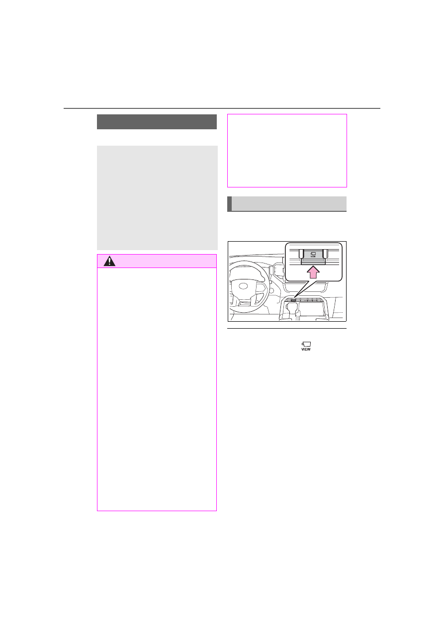
The camera switch is located as 
shown in the illustration.

The Multi-terrain Monitor is dis-
played by operating 

 when 

vehicle speed is approximately 10 
mph (16 km/h) or less. If the vehi-
cle speed exceeds approximately 
10 mph (16 km/h), the Multi-ter-
rain Monitor display is canceled.

Multi-terrain Monitor

*

The Multi-terrain Monitor 
helps the driver to check the 
vehicle surroundings. It 
assists in determining the 
conditions around the 
driver in a variety of situa-
tions, such as when judging 
conditions during off-road 
driving or checking for 
obstacles when parking.

WARNING

Observe the following precautions 

to avoid an accident that could 

result in death or serious injuries.

When using the Multi-terrain 

Monitor system

Never rely solely on the Multi-

terrain Monitor. As with 

unequipped vehicles, drive 

carefully while directly confirm-

ing the safety of your surround-

ings and the area to the rear of 

the vehicle. Take particular care 

to avoid parked cars and other 

obstacles.

Due to the characteristics of the 

camera lens, the actual position 

and distance of people and 

other obstacles will differ from 

those shown on the Multi-terrain 

Monitor screen. Directly con-

firm the safety of your surround-

ings before driving.

Do not drive while only looking 

at the screen. When driving, 

make sure to directly confirm 

the safety of your surroundings, 

such as by visually checking the 

area and using the vehicle’s 

mirrors.

In low temperatures, the screen 

may darken or the images may 

become faint. Images of moving 

objects in particular may distort 

or disappear from the screen. 

Therefore, make sure to drive 

carefully while directly visually 

confirming the safety of your 

surroundings.

Camera switch

353

4-5. Using the driving support systems

4

Dr

iv

ing

The screens that are displayed can be selected by the following but-
tons.

Front view & dual side view

Under vehicle terrain view & dual side view

Rear view & dual side view

Wide rear view

Auto mode on/off button (

P.355)

Multi-terrain Monitor on/off button

Panoramic View Monitor is displayed when the Multi-terrain Monitor is 
turned OFF. (

P.317)

The Multi-terrain Monitor is dis-
play a screen suitable for off-
road.

The driver can drive while 
confirming the following 
guidelines with a front view

• Distance with the obstacle in the 

front

• Estimated course line

The driver can drive while 
confirming the obstacle in the 
flank of tire neighborhood and 
the vehicle with a side screen

Menu button

When the front-wheel 
drive control switch is in 
“4L”, or “4H” and Multi-
terrain select is ON

354

4-5. Using the driving support systems

Front view & dual side view

Select the front view & dual side 
view button.

When the front view and side view 
screens are touched, each of the 
display sizes can be changed.

Under vehicle terrain view & 
dual side view

Select the under vehicle terrain 
view & dual side view button.

Under vehicle terrain view & 
dual side view (front magni-
fied)

When the under vehicle terrain 
view and side view screens are 
touched, each of the display sizes 
can be changed.

Rear view & dual side view

Select the rear view & dual side 
view button.

Wide rear view

Select the wide rear view button.

Checking the area to the 
front and sides of the vehi-
cle

Checking the condition of 
the road surface under the 
vehicle

Checking the area to the 
rear of the vehicle

355

4-5. Using the driving support systems

4

Dr

iv

ing

The rear view & dual side view 
and the wide rear displays can 
be switched by touching the 
screen.

The panoramic view monitor is 
displayed. (

P.317)

When automatic display mode is 
turned on, the Multi-terrain Mon-
itor screen is displayed in the 
following conditions, even if 


has not been operated.

• When the shift lever is shifted 

to D or N.

• When vehicle speed is 

reduced to approximately 10 
mph (16 km/h) or less.

The automatic display mode 
switches between on and off each 
time 

 is selected. When auto-

matic display mode is on, an indi-
cator illuminates on the icon.

Even when automatic display 
mode is on, the display can still be 
switched by pressing 

.

The front-wheel drive control switch in the case of “4L”, or “4H” and 
Multi-terrain select is ON, the Multi-terrain Monitor can display a 
screen suitable for off-road.

Front view & dual side view can be used to check the area around 
the front of the vehicle.

In addition to an image of the front of the vehicle, guide lines are 
displayed in a composite view to provide reference for when 
deciding a direction to move forward in.

When the front-wheel 
drive control switch is in 
“2H”, or “4H” and Multi-
terrain select is OFF

Automatic display mode

Screen display and functions

Front view & dual side view

356

4-5. Using the driving support systems

If the steering wheel is turned 270° or more, guide lines and other 
features to support turning are automatically displayed.

Front view & dual side view button

Under vehicle terrain view & dual side view button (

P.358)

Clinometer/slip display

Displays the vehicle’s estimated degree of incline or indicates a tire slip-
page. (

P.357, 358)

Automatic display button

Select to turn automatic display mode on/off. (

P.355)

Vehicle width lines (blue)

Shows guide lines of the vehicle’s width including the outside rear view mir-
rors.

1.5 ft. (0.5 m) distance guide line (red)

Show distance in front of the vehicle.
• Display points approximately 1.5 ft. (0.5 m) from the edge of the bumper.

3 ft. (1 m) distance guide line (blue)

6 ft. (2 m) distance guide line (blue)

Front tire course line (yellow)

Shows the estimated course of the front tires according to steering wheel 
position.

Forward movement guide line (blue)

Shows the estimated tire course of the tightest possible turn.

Front tire contact line (blue)

357

4-5. Using the driving support systems

4

Dr

iv

ing

Shows guide lines of where the front tire touches the ground.

Rear tire contact line (blue)

Shows guide lines of where the rear tire touches the ground.

Rear tire course line (yellow)

Shows the estimated course of the rear tires.

When the steering wheel is turned by 270° or more

Intuitive parking assist

When a sensor detects an obstacle, the direction of and the approximate 
distance to the obstacle are displayed and the buzzer sounds.

The screen can be displayed when the shift lever is in a position other 

than R.

When the intuitive parking assist detects an obstacle or another vehicle, a 

warning message pops up in the clinometer/slip display area.

Clinometer displays the vehicle inclination to the front, rear, left and 
right within a range of 0° to approximately 30°.

Degree markers of incline to the front and rear

Indicates the vehicle inclination in degrees in the front and rear directions.

Degree markers of incline to the left and right

Indicates the vehicle inclination in degrees in the left and right directions.

Pointer

Indicates the degree of the vehicle inclination in comparison to a parallel 
line.

Clinometer

358

4-5. Using the driving support systems

The display indicates the incline of the vehicle in degrees shown by the 

movement of the pointer and the rotation of the vehicle image.

The color of the degree markers of incline to the front, rear, left and right 

changes according to the current incline of the vehicle.

After the power switch is in ON, the degree of incline is not displayed until 

such information is determined.

The degree of incline showed on the clinometer is only an approximate 

indication, and may differ from the degree of incline measured using other 

equipment.

When tire slippage is detected, 
the clinometer display area is 
automatically switched to the 
slip display.

Tire display

Indicates the position of freely spin-
ning tires in yellow if the tire spins. 
(During Crawl Control is operating, 
all of the tires are indicated in yel-
low.)

Pop-up display of the intuitive 
parking assist

Displayed if an obstacle is detected 
while the intuitive parking assist is 
turned on.

Lines indicating current vehicle and tire position are displayed in a 
composite view on an image taken approximately 32 ft. (10m) 
behind the current vehicle position and assists the driver to check 
conditions underneath the vehicle or determine the position of the 
front tires.

Slip display

Under vehicle terrain view & dual side view

359

4-5. Using the driving support systems

4

Dr

iv

ing

Current vehicle position

Image displayed in the under vehicle terrain view (image taken 
approximately 32 ft. (10m) behind the current vehicle position)

Vehicle position at the time the image was taken (approximately 
32 ft. (10m) behind the current vehicle position)

Under vehicle terrain view & dual side view

Under vehicle terrain view & dual side view (front magnified)

Front view & dual side view button (

P.355)

Under vehicle terrain view & dual side view button

Clinometer/slip display

Displays the vehicle’s estimated degree of incline or indicates a tire slip-
page. (

P.357, 358)

Automatic display button

Select to turn automatic display mode on/off. (

P.355)

Tire position indicator lines (black or white)

Indicates the estimated position of the front tires.

Displaying the under vehicle terrain view

360

4-5. Using the driving support systems

Vehicle position indicator lines (blue)

Indicates the estimated position of the vehicle.

1.5 ft. (0.5 m) distance guide line (red or black)

Show distance in front of the vehicle.
• Display points approximately 1.5 ft. (0.5 m) from the edge of the bumper.

Front tire contact line (blue)

Shows guide lines of where the front tire touches the ground.

Vehicle width lines (blue)

Shows guide lines of the vehicle’s width including the outside rear view mir-
rors.

Rear tire contact line (blue)

Shows guide lines of where the rear tire touches the ground.

Intuitive parking assist

When a sensor detects an obstacle, the direction of and the approximate 
distance to the obstacle are displayed and the buzzer sounds.

The screen can be displayed when the shift lever is in a position other 

than R.

While the under vehicle terrain view is displayed, if the vehicle speed 

reaches or exceeds approximately 3 mph (5 km/h), the screen automati-

cally returns to the front view display.

In the following situations, the under vehicle terrain view selection button 

cannot be operated.

• The vehicle is not completely stopped

• After the hybrid system starts, a fixed distance or more has not been 

driven

• After the front-wheel drive control switch is shifted to “4L”, a fixed distance 

or more has not been driven

In the following situations, the system may not operate normally, or it may 

not be possible to switch to the under vehicle terrain view.

• The road is covered with snow

• It is nighttime and the road has no illumination

• Dirt or foreign matter is adhering to the camera lens

• There is water in front of the vehicle (a river, puddle, sea water, etc.)

361

4-5. Using the driving support systems

4

Dr

iv

ing

The rear view & dual side view/wide rear view screen provide sup-
port when checking the areas of behind the vehicle and around the 
vehicle while backing up, for example while parking.
The screens will be displayed when the shift lever is in R.

Rear view & dual side view

Wide rear view

Rear view & dual side view

Wide rear view button

Clinometer/slip display

WARNING

The tire position indicator lines and vehicle position indicator lines may 

differ from actual vehicle positions depending on the number of passen-

gers, cargo weight, road grade, road surface conditions, brightness of 

the surrounding environment, etc. Always drive the vehicle while con-

firming the safety of your surroundings.

The image displayed is one that was previously taken at a point approx-

imately 32 ft. (10m) behind the current vehicle position. In cases such 

as when objects move after the image is taken, the image displayed on 

the screen may differ from the actual state.

Rear view & dual side view/wide rear view

362

4-5. Using the driving support systems

Displays the vehicle’s estimated degree of incline or indicates a tire slip-
page. (

P.357, 358)

1.5 ft. (0.5 m) distance guide line (red)

Show distance in rear of the vehicle.
• Display points approximately 1.5 ft. (0.5 m) from the edge of the bumper.

Vehicle width guide lines (blue)

Displays a guide path when the vehicle is being backed straight up.

Front tire contact line (blue)

Shows guide lines of where the front tire touches the ground.

Rear tire contact line (blue)

Shows guide lines of where the rear tire touches the ground.

Rear Cross Traffic Alert

When a sensor detects a vehicle approaching from the rear, the direction of 
the vehicle approaching from the rear is displayed and the buzzer sounds.

Intuitive parking assist

When a sensor detects an obstacle, the direction of and the approximate 
distance to the obstacle are displayed and the buzzer sounds.

The screen can be displayed when the shift lever is in R.

For details about the Rear Cross Traffic Alert function. (

P.301)

If the back door is not closed, guide lines will not be displayed. If the guide 

lines do not display even when the back door is closed, have the vehicle 

inspected at your Toyota dealer.

P.339

P.350

WARNING

The tire position indicator lines and vehicle position indicator lines may 

differ from actual vehicle positions depending on the number of passen-

gers, cargo weight, road grade, road surface conditions, brightness of 

the surrounding environment, etc. Always drive the vehicle while con-

firming the safety of your surroundings.

Multi-terrain Monitor pre-
cautions

Things you should know

363

4-5. Using the driving support systems

4

Dr

iv

ing

*

: If equipped

Height control switch

Height control mode select 
switch

Operating the switch change 
vehicle rear height as follows:

Lower

Higher

Vehicle height can be adjusted 
only when the hybrid system is 
operating.
The selected height mode will 
be shown on the electronically 
modulated air suspension dis-
play.
The selected mode will flash 
while the height mode is being 
changed.

Height modes

“N” mode (normal mode): For 
ordinary driving

Normal height

“HI” mode (high mode): For 
driving on bumpy roads 1.6 in. 
(40 mm) higher than the nor-
mal height

The “HI” mode is unavailable when 
the vehicle’s speed exceeds 18 
mph (30 km/h).
When the vehicle’s speed exceeds 
18 mph (30 km/h), the height will be 
adjusted to the normal height auto-
matically.

Electronically modu-

lated air suspension

*

The electronically modu-
lated air suspension allows 
the driver to control the 
vehicle’s height in order to 
adjust for driving condi-
tions.

Select the desired height 
with the height control 
switch.

Height control switch

Selecting vehicle height

364

4-5. Using the driving support systems

“LO” mode (low mode): For 
the ease of egress/ingress 
and loading luggage

1.2 in. (30 mm) lower than the nor-
mal height
The “LO” mode is unavailable when 
the vehicle’s speed exceeds 8 mph 
(12 km/h).
When the vehicles speed exceeds 
8 mph (12 km/h), the height will be 
adjusted to the normal height auto-
matically.

When the height control mode 
select switch is pressed, the 
vehicle height is fixed at the cur-
rent height.

The “MAN.” indicator is displayed 
on the multi-information display and 
the automatic leveling function 
turned off.

The height can be adjusted by 
pressing the height control 
switch.

Press the switch again or when the 
vehicle’s speed exceeds 18 mph 
(30 km/h), the height will be 
adjusted to the normal height auto-
matically.

Automatic leveling function

Regardless of the number of occu-

pants or the luggage load, vehicle 

height in any mode is always 

adjusted to a fixed height by the 

automatic leveling function.

When “HI” mode is selected

The vehicle height will change to “N” 

mode when driving at the speeds of 

18 mph (30 km/h).

When “LO” mode is selected

The vehicle height will change to 

“N” mode when vehicle speed 

exceeds 8 mph (12 km/h).

This mode allows for easy access 

to the vehicle (getting in and out) 

and easy loading and unloading.

The electronically modulated 

air suspension will not operate 

in the following cases:

The underbody of the vehicle is 

touching the surface of the road.

The area around the suspension 

is covered with ice.

The height control indicators will 

blink, turn off and then turn on con-

tinuously to indicate that the elec-

tronically modulated air suspension 

is not operational.

To re-enable operation, turn off the 

hybrid system and then restart it.

Even if you hear an operating 

noise

This does not indicate a problem in 

the electronically modulated air sus-

pension.

The electronically modulated 

air suspension failure warning

The warning message is displayed 

on the multi-information display, and 

the electronically modulated air sus-

pension cannot be activated until 

the malfunction is corrected.

Stop the hybrid system and start 

again. If the warning message turns 

off, the system operating correctly. If 

the warning message continues to 

Disabling the height con-
trol

365

4-5. Using the driving support systems

4

Dr

iv

ing

be displayed, have your vehicle 

inspected by your Toyota dealer as 

soon as possible.

When the 

 indicator turns on

Indicates a malfunction in the air 

suspension system.

Have the vehicle inspected by your 

Toyota dealer immediately. (

P.89, 

516)

WARNING

The electronically modulated 

air suspension must be 

turned off in the following cir-

cumstances:

Otherwise, the automatic leveling 

function may cause the vehicle’s 

height to change, and you may 

catch part of your body in the 

vehicle, resulting in an unex-

pected accident or injury:

When driving through water 

such as shallow streams (Put 

the vehicle height in “HI” mode 

and turn off the electronically 

modulated air suspension. Drive 

at 18 mph [30 km/h] or slower.)

When jacking up the vehicle, 

installing tire chains or tying the 

vehicle with chains/wires for 

transportation via flat bed truck 

(Turn the system to the manual 

mode and stop the hybrid sys-

tem.)

When the vehicle must be 

towed (Put the vehicle height in 

“N” mode and turn the system to 

the manual mode.)

When the vehicle gets stuck 

(Turn the system to the manual 

mode.)

When disconnecting a trailer 

(Put the vehicle height in “N” 

mode and turn the system to the 

manual mode.)

Selecting the correct height 

mode

Observe the following precautions 

to prevent accidents or injury.

Failure to do so may cause dam-

age to parts of the vehicle, as well 

as dangerous handling character-

istics, which may lead to fatal or 

injury accidents.

Before you lower the vehicle’s 

height, check under the vehicle 

to make sure that no one is 

there.

“HI” mode should only be used 

when driving on rough roads, for 

example when driving off-road.

Because the vehicle’s center of 

gravity will become higher when 

in the mode, the vehicle may 

become unstable when turning 

abruptly, resulting in an acci-

dent.

Do not select “HI” mode when 

you load cargo on the roof lug-

gage carrier.

Because the vehicle’s center of 

gravity will become higher when 

in the mode, the vehicle may 

become unstable when turning 

abruptly, resulting in an acci-

dent.

NOTICE

Be careful in any place where 

overhead space is limited.

When changing to a higher mode 

or after unloading, the vehicle 

height will rise. This may cause 

damage to the vehicle.

Do not select “LO” mode 

when driving on bumpy 

roads.

If the underbody of the vehicle 

touches a rugged road surface, 

the vehicle may be damaged.

366

4-5. Using the driving support systems

“DRIVE MODE” switch

Mode select switch

Multi-information display 
(

P.97)

1

Press the “DRIVE MODE” 
switch.

The indicator 

 on the switch will 

NOTICE

Do not change the vehicle 

height frequently.

The compressor might overheat 

and cause the operation to stop.

When on the extremely 

uneven roads with rocks

Sometimes the vehicle height is 

not adjusted because it is judged 

as uneven road driving.

Driving mode select 

switch

The driving modes can be 
selected to suit driving con-
dition.

System components

Selecting the driving 
mode

367

4-5. Using the driving support systems

4

Dr

iv

ing

turn on.

2

Select the driving modes on 
the multi-information display 
while turning the mode select 
switch left and right.

Vehicles without Adaptive 
Variable Suspension system

Multi-information display

• “NORMAL” mode
Provides an optimal balance of fuel 
economy, quietness, and dynamic 
performance. Suitable for city driv-
ing.
• “ECO” mode
Helps the driver accelerate in an 
eco-friendly manner and improve 
fuel economy through moderate 
throttle characteristics and by con-

trolling the operation of the air con-
ditioning system (heating/cooling). 
The “ECO” indicator comes on.
• “SPORT” mode
Assists acceleration response by 
controlling the transmission, engine 
and steering. Suitable for when pre-
cise handling is desirable, for 
example when driving on mountain 
roads. The “SPORT” indicator 
comes on.

Vehicles with Adaptive Vari-
able Suspension system

Multi-information display

• “NORMAL” mode
Provides an optimal balance of fuel 
economy, quietness, and dynamic 
performance. Suitable for city driv-
ing.
• “COMFORT” mode
By controlling the suspension, rid-
ing comfort is further enhanced. 
Suitable for city driving. The “COM-
FORT” indicator comes on.
• “ECO” mode
Helps the driver accelerate in an 
eco-friendly manner and improve 


Content      ..     20      21      22      23     ..