Toyota Raize (2023 year). Manual in english - page 4
 

  Index      Toyota     Toyota Raize (2023 year). Manual in english


Search            copyright infringement  


Content      ..     2      3      4      5     ..


Toyota Raize (2023 year). Manual in english - page 4


61

1-2. Safety information for children

For safety and s

ecurity

1

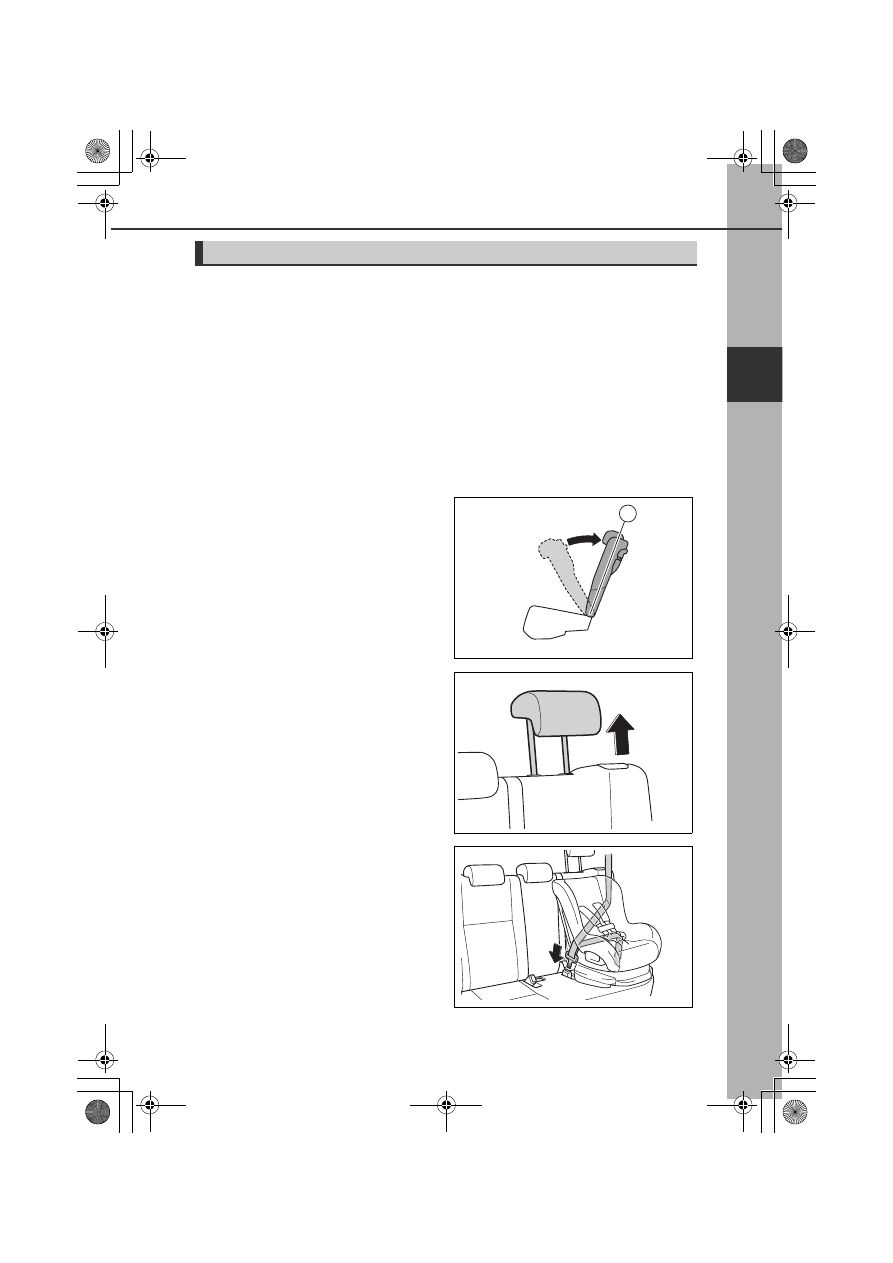
Child restraint system fixed with a seat belt

Installing child restraint system using a seat belt

Install the child restraint system in accordance to the operation manual

enclosed with the child restraint system.
If the child restraint system on hand is not within the “universal” category

(or the necessary information is not in the table), refer to the “Vehicle List”

provided by the child restraint system maker for various possible installa-

tion positions, or check the compatibility after asking the retailer of the

child seat. (

P. 56)

a

If installing the child restraint system to the front passenger seat is

unavoidable, refer to P. 53 for front passenger seat adjustment.

b

Tilt the seatback forward and

adjust it back to its 1st fixed posi-

tion (

a

)

c

Raise the head restraint to its

highest position

Remove the head restraint if it inter-

feres with proper child restraint system

installation. (

P. 152)

d

Run the seat belt through the

child restraint system and insert

the plate into the buckle. Make

sure that the belt is not twisted.

Securely fix the seat belt to the child

restraint system in accordance to the

directions enclosed with the child

restraint system.

1

KBRO110719

KBRO110714

KBRO110704

62

1-2. Safety information for children

e

If your child restraint system is

not equipped with a lock off (a

seat belt locking feature), secure

the child restraint system using a

locking clip.

f

After installing the child restraint system, rock it back and forth to

ensure that it is installed securely.

Removing a child restraint system installed with a seat belt

Press the buckle release button and fully retract the seat belt.

When releasing the buckle, the child restraint system may spring up due to the

rebound of the seat cushion. Release the buckle while holding down the child

restraint system.
Since the seat belt automatically reels itself, slowly return it to the stowing position.

When installing a child restraint system

You may need a locking clip to install the child restraint system. Follow the

instructions provided by the manufacturer of the system. If your child restraint

system does not provide a locking clip, you can purchase the following item

from any authorized Toyota retailer or Toyota authorized repairer, or any relia-

ble repairer: Locking clip for child restraint system (Part No. 73119-22010)

WARNING

When installing a child restraint system

Observe the following precautions.
Failure to do so may result in death or serious injury.

Do not allow children to play with the seat belt. If the seat belt becomes
twisted around a child’s neck, it may lead to choking or other serious injuries

that could result in death. If this occurs and the buckle cannot be unfas-

tened, scissors should be used to cut the belt.

Ensure that the belt and plate are securely locked and the seat belt is not
twisted.

Shake the child restraint system left and right, and forward and backward to
ensure that it has been securely installed.

After securing a child restraint system, never adjust the seat.

KBPA110705

63

1-2. Safety information for children

WARNING

For safety and s

ecurity

1

When a junior seat (booster seat) is installed, always ensure that the shoul-
der belt is positioned across the center of the child’s shoulder. The belt

should be kept away from the child’s neck, but not so that it could fall off the

child’s shoulder.

Follow all installation instructions provided by the child restraint system man-
ufacturer.

Child restraint system fixed with an ISOFIX lower anchorage

ISOFIX lower anchorages (ISOFIX child restraint system)

Lower anchorages are provided for

the rear outboard seats. (Marks dis-

playing the location of the anchor-

ages are attached to the seats.)

Installation with ISOFIX lower anchorage (ISOFIX child restraint 
system)

Install the child restraint system in accordance to the operation manual

enclosed with the child restraint system.
If the child restraint system on hand is not within the “universal” category

(or the necessary information is not in the table), refer to the “Vehicle List”

provided by the child restraint system maker for various possible installa-

tion positions, or check the compatibility after asking the retailer of the

child seat. (

P. 56)

a

Tilt the seatback forward and

adjust it back to its 1st fixed posi-

tion (

a

)

KBRO110717

1

KBRO110719

64

1-2. Safety information for children

b

Raise the head restraint to its

highest position

Remove the head restraint if it inter-

feres with proper child restraint system

installation. (

P. 152)

c

Installing the child restraint sys-

tem to the seat

Attach the child restraint system

attachment buckles to the child

restraint system attachment points.
Follow the instructions in the manual

provided with your child restraint sys-

tem.

d

After installing the child restraint system, rock it back and forth to

ensure that it is installed securely.

When using an “i-Size MIDI”

Adjust the support leg and ISOFIX connectors as follows:

a

Lock the ISOFIX connectors where

number 4 can be seen.

b

Lock the support leg where 6 and

half holes can be seen.

KBRO110714

KBRO110708

1

2

KBRO110720TN

65

1-2. Safety information for children

For safety and s

ecurity

1

WARNING

When installing a child restraint system

Observe the following precautions.
Failure to do so may result in death or serious injury.

Shake the child restraint system left and right, and forward and backward to
ensure that it has been securely installed.

After securing a child restraint system, never adjust the seat.

When using the lower anchorages, be sure that there are no foreign objects
around the anchorages and that the seat belt is not caught behind the child

restraint system.

Follow all installation instructions provided by the child restraint system man-
ufacturer.

66

1-2. Safety information for children

Using a top tether anchorage

Top tether anchorage

Top tether anchorages are provided for the outboard rear seat.
Use top tether anchorages when fix-

ing the top strap.

Fixing the top strap to the top tether anchorage

Install the child restraint system according to the instructions in the man-

ual included with the child restraint system.

a

Fix the hook to the top tether

anchorage, and tighten the top

strap

Make sure that the top strap is taut and

that the hook is securely fixed.

a

Hook

b

Top strap

b

Make sure that the installed child restraint system is securely locked by

pushing it forward and rearward and to the right and left

KBRO110703TN

Top tether anchorages

Slit

KBRO110709

b

a

67

1-2. Safety information for children

For safety and s

ecurity

1

WARNING

When installing a child restraint system

Observe the following precautions.
Failure to do so may result in death or serious injury.

Firmly attach the top strap and make sure that the belt is not twisted.

Do not attach the top strap to anything other than the top tether anchorage.

Shake the child restraint system left and right, and forward and backward to
ensure that it has been securely installed.

After securing a child restraint system, never adjust the seat.

Follow all installation instructions provided by the child restraint system man-
ufacturer.

Rear head restraints

When installing the child restraint system with the head restraint raised,

make sure that insert the top strap under the head restraint. Wrapping the

top strap over the head restraint can be dangerous, for it prevents the child

restraint system from being fixed securely, leading to severe life-threatening

injury in the event of a collision.

When installing the child restraint system with the head restraint being

raised, after the head restraint has been raised and then the top tether

anchorage has been fixed, do not lower the head restraint. When the head

restraint is lowered, the top strap may sag against the head restraint, caus-

ing the child seat to move in the event of a collision or other accidents,

resulting in serious injury or death in the worst case.

If you need to remove the head restraint, securely fix it in a safe place.

68

: If equipped

1-3. Emergency assistance

eCall

*

eCall is a telematics service that uses Global Navigation Satellite Sys-

tem (GNSS) data and embedded cellular technology to enable the fol-

lowing emergency calls to be made: Automatic emergency calls

(Automatic Collision Notification) and manual emergency calls (by

pressing the “SOS” button). This service is required by United Arab

Emirates Regulations.

*

Operates within the eCall coverage.

System components

a

“SOS” button*

Make  sure  to  open  the  cover  before

pressing the “SOS” button.

b

Indicator lights

c

Speaker

d

Microphone

*

This button is intended for communi-
cation with the eCall system operator.
Other SOS buttons available in other
systems of a motor vehicle do not
relate to the device and are not
intended for communication with the
eCall system operator.

1

2

4

3

KBRO130101E

69

1-3. Emergency assistance

For safety and s

ecurity

1

Emergency Notification Services

Automatic Emergency Calls

If any airbag deploys, the system is designed to automatically call the eCall

control center.* The answering operator receives the vehicle’s location,

the time of the incident and the vehicle VIN, and attempts to speak with

the vehicle occupants to assess the situation. If the occupants are unable

to communicate, the operator automatically treats the call as an emer-

gency and contacts the nearest emergency services provider (999 system

etc.) to describe the situation and request that assistance be sent to the

location.

*

In some cases, the call cannot be made. (

P. 70)

Manual Emergency Calls

In the event of an emergency, press the “SOS” button to call the eCall con-

trol center.* The answering operator will determine your vehicle’s loca-

tion, assess the situation, and dispatch the necessary assistance required.

If you accidentally press the “SOS” button, tell the operator that you are not experi-

encing an emergency.

*

In some cases, the call cannot be made. (

P. 70)

Indicator lights

When the engine switch is turned to “ON”, the red indicator light will illumi-

nate for 10 seconds and then the green indicator light will illuminate, indi-

cating that the system is enabled. The indicator lights indicate the following:

If the green indicator light illuminates and stays on, the system is ena-

bled.

If the green indicator light flashes twice per second, an automatic or

manual Emergency Call is being made.

If no indicator lights illuminate, the system is not enabled.

If the red indicator light illuminates at any time other than immediately

after the engine switch is turned to “ON”, the system may be malfunc-

tioning or the backup battery may be depleted.

If the red indicator light blinks for approximately 30 seconds during an

Emergency Call, the call has been disconnected or the cellular network

signal is weak.

The service life of the backup battery does not exceed 3 years.

70

1-3. Emergency assistance

Free/Open Source Software Information

This product contains Free/Open Source Software (FOSS).
The license information and/or the source code of such FOSS can be found at

the following URL.
http://opensource.lge.com/

WARNING

When the Emergency Call may not be made

It may not be possible to make Emergency Calls in any of the following situa-
tions. In such cases, report to emergency services provider (999 system etc.)

by other means such as nearby public phones.

Even when the vehicle is in the cellular phone service area, it may be diffi-

cult to connect to the eCall control center if the reception is poor or the

line is busy. In such cases, even though the system attempts to connect to

the eCall control center, you may not be able to connect to the eCall con-

trol center to make Emergency Calls and contact emergency services.

When the vehicle is out of the cellular phone service area, the Emergency

Calls cannot be made.

When any related equipment (such as the “SOS” button panel, indicator

lights, microphone, speaker, DCM, antenna, or any wires connecting the

equipment) is malfunctioning, damaged or broken, the Emergency Call

cannot be made.

During an Emergency Call, the system makes repeated attempts to con-

nect to the eCall control center. However, if it cannot connect to the eCall

control center due to poor radio wave reception, the system may not be

able to connect to the cellular network and the call may finish without con-

necting. The red indicator light will blink for approximately 30 seconds to

indicate this disconnection.

If the battery’s voltage decreases or there is a disconnection, the system may
not be able to connect to the eCall control center.

71

1-3. Emergency assistance

WARNING

For safety and s

ecurity

1

When the Emergency Call system is replaced with a new one

The Emergency Call system should be registered. Contact your Toyota dealer.

For your safety

Please drive safely.
The function of this system is to assist you in making the Emergency Call in

case of accidents such as traffic accidents or sudden medical emergencies,

and it does not protect the driver or passengers in any way. Please drive

safely and fasten your seatbelts at all times for your safety.

In case of an emergency, make lives the top priority.

If you smell anything burning or other unusual smells, leave the vehicle and
evacuate to a safe area immediately.

Since the system detects shocks, the automatic reporting may not always
occur synchronized with the operation of the airbag system. (If the vehicle is

struck from behind, etc.)

For safety, do not make the Emergency Call while driving.
Making calls during driving may cause mishandling of the steering wheel,

which may lead to unexpected accidents.
Stop the vehicle and confirm the safety of your surroundings before making

the Emergency Call.

When changing fuses, please use the specified fuses. Using other fuses may
cause ignition or smoke in the circuit and lead to a fire.

Using the system while there is smoke or an unusual smell may cause a fire.
Stop using the system immediately and consult your Toyota dealer.

NOTICE

To prevent damage

Do not pour any liquids onto the “SOS” button panel, etc. and do not impact it.

If the “SOS” button panel, speaker or microphone malfunctions during an 
Emergency Call or manual maintenance check

It may not be possible to make Emergency Calls, confirm the system status, or

communicate with the eCall control center operator. If any of the above equip-

ment is damaged, please consult your Toyota dealer.

72

1-4. Theft deterrent system

Engine immobilizer system

The vehicle’s keys have built-in transponder chips, and the vehicle

cannot be started using a key that has not been previously registered

in the vehicle.
Never leave the keys inside the vehicle when you leave the vehicle.

This system is designed to help prevent vehicle theft but does not guarantee

absolute security against all vehicle thefts.

Vehicles without key-free system

After the key has been removed

from the engine switch, the security

indicator on the meter flashes indi-

cating the system activation.

Inserting the registered key to the engine

switch will deactivate the system and turn

off the security indicator on the meter.

Vehicles with key-free system

The security indicator on the meter

flashes after the engine switch has

been turned to “OFF” to indicate that

the system is operating.

The system is canceled and the security

indicator on the meter turns off when

you turn the engine switch to “ACC” or

“ON” while carrying the registered key.

Maintenance

The engine immobilizer system is maintenance-free.

Conditions that may cause the system to malfunction

If the key touches or is covered by a metal object

If the key is in close proximity to or touching a key for the security system
(key with a built-in transponder chip) of another vehicle

NOTICE

To ensure the engine immobilizer system operates properly

Do not modify or remove the system.
If modified or removed, the proper operation of the system cannot be guaranteed.

KBRO120101E

73

1-4. Theft deterrent system

: If equipped

For safety and s

ecurity

1

Alarm

The alarm

The alarm uses the emergency flashers and sound to give an alert when

an intrusion is detected.
The alarm is triggered in the following situations when the alarm is set:

A locked door is unlocked and opened in any way other than using the

key-free function or wireless remote control.

The hood is opened.

Setting the alarm system

The alarm will be set in the following

cases:
Close the doors and hood, and lock

all the doors using the key-free func-

tion or wireless remote control.

When the doors are locked auto-

matically by the security feature.

(

P. 139)

The indicator light is flashing when the

system is set.

Deactivating the alarm

Do one of the following to deactivate the alarm:

Unlock the doors using the key-free function or wireless remote control.

Turn the engine switch to “ON”, or start the engine.

KBRO120101E

74

1-4. Theft deterrent system

Stopping the alarm

Do one of the following to stop the alarm:

Press the lock or unlock button of the wireless remote control.

Press the lock/unlock switch on the front door while carrying the elec-

tronic key with you.

Press the lock button on the back door while carrying the electronic key

with you (when opening the driver’s door).

Press the back door opener switch on the back door while carrying the

electronic key with you (when closing the driver’s door).

Get in the car with the electronic key.

Turn the engine switch to “ON”, or start the engine.

If the electronic key does not operate properly

If the electronic key does not work due to battery depletion, etc., perform

the following operation.

a

Vehicles with a continuously vari-

able transmission:

Depress the brake pedal.

Vehicles with a manual transmis-

sion:

Depress the clutch pedal.

b

Touch the electronic key to the

engine switch, as shown in the

illustration.

KBRO820801E

75

1-4. Theft deterrent system

For safety and s

ecurity

1

System maintenance

The vehicle has a maintenance-free type alarm system.

Items to check before locking the vehicle

To prevent unexpected triggering of the alarm and vehicle theft, make sure of

the following:

Nobody is in the vehicle.

The windows are closed before the alarm is set.

No valuables or other personal items are left in the vehicle.

Triggering of the alarm

The alarm may be triggered in the following situations:
(Stopping the alarm deactivates the alarm system.)

The doors are unlocked using the
key.

A person inside the vehicle opens a
door or hood.

When the battery is disconnected

Be sure to deactivate the alarm system.
If the battery is discharged before deactivating the alarm system, the alarm

may be triggered when the battery is reconnected.

NOTICE

To ensure the system operates correctly

Do not modify or remove the system. If modified or removed, the proper oper-

ation of the system cannot be guaranteed.

KBRO120102E

KBRO120103E

78

2-1. Instrument cluster

Warning lights and indicators

Warning lights and indicators on the upper part of meter and inside

rear view mirror inform the condition the vehicle is in.
For the purpose of explanation, the following illustration displays all

warning lights and indicators illuminated.

Meters

Vehicles without TFT color multi-information display 

(vehicles without tachometer)

Vehicles without TFT color multi-information display 
(vehicles with tachometer)

KBRO210103E

KBRO210101E


Content      ..     2      3      4      5     ..