Toyota 86 (2023 year). Manual in english - page 15
 

  Index      Toyota     Toyota 86 (2023 year). Manual in english


Search            copyright infringement  


Content      ..     13      14      15      16     ..


Toyota 86 (2023 year). Manual in english - page 15


237

4-6. Using other driving systems

4

Dr

iv

ing

be changed by operating the 
multimedia system screen. 
(

P.400)

Safety tips regarding the 
BSD/RCTA approach indi-
cator/warning buzzer

In the following cases, opera-
tion of the BSD/RCTA 
approach indicator and the 
warning buzzer may be 
delayed or the system may 
fail to issue these warnings.

• When a vehicle moves to the 

neighboring lane from a lane next 
to the neighboring lane

• When driving on a steep incline 

or on repeated sharp uphill and 
downhill grades

• When going beyond a pass
• When both your vehicle and a 

vehicle driving on a neighboring 
lane are driving on the far side of 
each lane.

• When several narrowly-spaced 

vehicles are approaching in a row

• In low radius bends (tight bends 

or when making turns at an inter-
section)

• When there is a difference in 

height between your lane and the 
neighboring lane

• Immediately after the BSD/RCTA 

is activated by touching 
“BSD/RCTA”

• Immediately after the shift lever is 

shifted to R

• When extremely heavy cargo is 

loaded in the trunk

During reversing, operation of 

the BSD/RCTA approach indi-
cator and the warning buzzer 
may be delayed or the system 
may fail to issue these warn-
ings under the following con-
ditions.

• When backing out of an angled 

parking space

• When a large-sized vehicle is 

parked next to your vehicle (That 
vehicle prevents the propagation 
of radar waves.)

• When reversing on sloped roads
• When reversing at a high speed

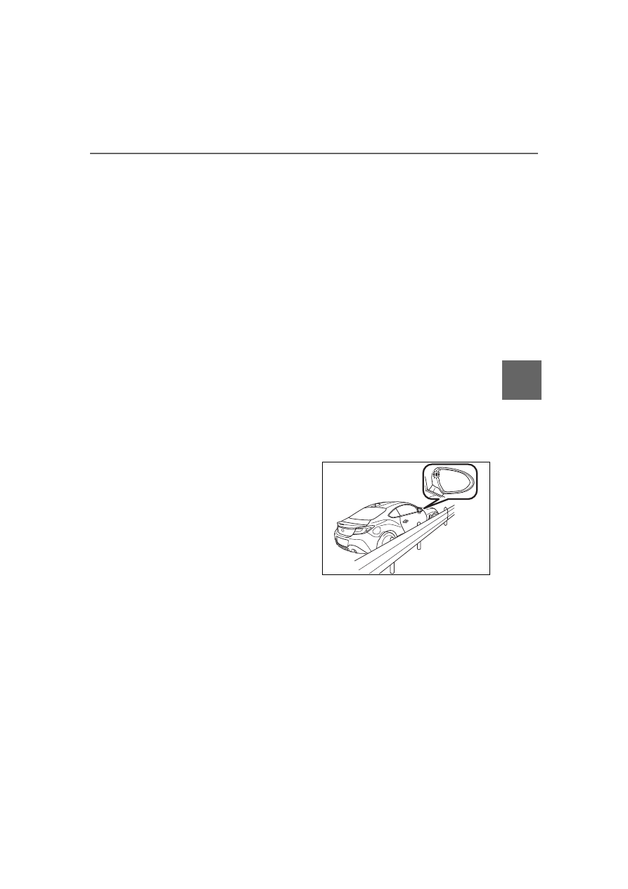
The BSD/RCTA approach 
indicator may illuminate when 
driving close to solid objects 
on the road or road side (such 
as guardrails, tunnels and 
sidewalls).

When turning at an intersec-
tion in urban areas, or a multi-
lane intersection, the 
BSD/RCTA approach indica-
tor may flash.

If a building or a wall exists in 
the reversing direction, the 
BSD/RCTA approach indica-
tor may flash and the warning 
buzzer may sound.

238

4-6. Using other driving systems

In the following cases, the 
system may detect a vehicle 
driving two lanes away from 
your vehicle.

• When your vehicle drives on the 

near side of its lane from the cor-
responding vehicle

• When the vehicle driving two 

lanes away drives on the near 
side of its lane from your vehicle

System temporary stops

This display appears when the 
system is used at extremely 
high or low temperatures or 
when abnormal voltage exists. 
Once these conditions are cor-
rected, the system will recover 
from the temporary stop condi-
tion and the indicator will disap-
pear.
If the indicator remains dis-
played for a prolonged time, 
have the system inspected at a 
Toyota dealer.

“BSD/RCTA Disabled”
BSD/RCTA OFF indicator

System temporary stops 
due to reduced radar sensi-
tivity

This display appears when the 
detectability of the radar sen-
sors is reduced. Once the condi-
tion is corrected, the system will 
recover from the temporary stop 
condition and the indicator will 
disappear.
If the indicator remains dis-
played for a prolonged time, 
have the system inspected at a 
Toyota dealer.

“BSD/RCTA Disabled Sen-
sor Blocked”
BSD/RCTA OFF indicator

System malfunction

This display appears when a 
malfunction occurs in the sys-
tem. Contact a Toyota dealer 
and have the system inspected.

BSD/RCTA OFF indicator

A

BSD/RCTA warning light

A

239

4-6. Using other driving systems

4

Dr

iv

ing

“BSD/RCTA Disabled Check 
Owner's Manual”
BSD/RCTA warning light

To turn the BSD/RCTA system 
on and off, operate the 
multi-information display 
(

P.400) or multimedia system 

screen (Refer to “MULTIMEDIA 
OWNER'S MANUAL”).
When the BSD/RCTA system is 
turned OFF, the BSD/RCTA 
OFF indicator on the multi-infor-
mation display will illuminate.

In the following cases, turn off the 

BSD/RCTA system. The system 

may not operate properly due to 

blocked radar waves.

• When towing the vehicle

• When a bicycle carrier or other 

item is fitted to the rear of the vehi-

cle

• When using a chassis dynamome-

ter or free roller device, etc.

• When running the engine and 

making the wheels rotate while lift-

ing up the vehicle

If the engine switch is turned to 

OFF, the last known status of the 

system is maintained. For exam-

ple, if the engine switch is turned 

to OFF with the BSD/RCTA deac-

tivated, the BSD/RCTA remains 

deactivated the next time the 

engine switch is turned to ON.

The radar sensors, one on each 
side of the vehicle, are mounted 
inside the rear bumper.

Radar sensors

If the radar sensors require repair or 

replacement, or the bumper area 

around the radar sensors requires 

repair, paintwork or replacement, 

contact your Toyota dealer for assis-

tance.

To turn on/off the 
BSD/RCTA

A

Handling of radar sensors

NOTICE

To ensure correct operation of the 

BSD/RCTA, observe the follow-

ing precautions.

A

240

4-6. Using other driving systems

*

: If equipped

The Reverse Automatic Braking 

(RAB) system records and stores 

the following data when automatic 

braking operates. It does not record 

conversations, personal information 

or other audio data.

Distance from the object

Vehicle speed

Accelerator pedal operation status

Brake pedal operation status

Shift lever position

Outside temperature

The sensitivity setting of the sonar 

sensors

Toyota and third parties contracted 

by Toyota may acquire and use the 

recorded data for the purpose of 

vehicle research and development. 

Toyota and third parties contracted 

by Toyota will not disclose or pro-

vide the acquired data to any other 

third party except under the follow-

ing conditions.

The vehicle owner has given 

his/her consent.

The disclosure/provision is based 

NOTICE

Always keep the bumper sur-

face near the radar sensors 

clean.

Do not affix any stickers or other 

items on the bumper surface 

near the radar sensors. For 

details, consult your Toyota 

dealer.

Do not modify the bumper near 

the radar sensors.

Do not paint the bumper near 

the radar sensors.

Do not expose the bumper near 

the radar sensors to strong 

impacts. If a sensor becomes 

misaligned, a system malfunc-

tion may occur, including the 

inability to detect vehicles enter-

ing the detection areas. If any 

strong shock is applied to the 

bumper, be sure to contact your 

Toyota dealer for inspection.

Do not disassemble the radar 

sensors.

Reverse Automatic 

Braking (RAB) system

*

Reverse Automatic Braking 
(RAB) is a system designed 
to help avoid collisions or 
reduce collision damage 
when reversing the vehicle. 
If a wall or an obstacle is 
detected in the reversing 
direction, the system will 
notify the driver with a 
warning sound and may 
activate the vehicle’s brakes 
automatically.

241

4-6. Using other driving systems

4

Dr

iv

ing

on a court order or other legally 

enforceable request.

Data that has been modified so 

that the user and vehicle cannot 

be identified is provided to a 

research institution for statistical 

processing or similar purposes.

The Reverse Automatic Braking 
(RAB) system will operate the 
following 2 functions using 4 
sonar sensors.

Sonar Audible Alarm

The Reverse Automatic Braking 
(RAB) system detects objects rear-
ward and warns the driver by warn-
ing message on the multimedia 
system screen and warning beeps.

Automatic Braking

The automatic braking detects 
objects rearward and if there is a 
high risk of a collision, the system 
decelerates the vehicle and con-
trols the braking to reduce damage.

When reversing

When either strong automatic 
braking or torque control is 
applied to prevent collision (in 

WARNING

Reverse Automatic Braking 

(RAB) is not a system intended 

to replace the driver’s responsi-

bility to check their surroundings 

for vehicles or obstacles to 

avoid a collision.

The driver is responsible for 

driving safely. Before reversing, 

be sure to first depress the 

brake pedal and visually check 

the surroundings.

There are some cases in which 

the vehicle cannot avoid colli-

sion, because the system oper-

ation has limitations. The 

warning sound or automatic 

braking may be delayed or may 

not operate at all even when an 

obstacle is present.

Make sure to set the Automatic 

Braking to OFF when the vehi-

cle is on the free roller or on the 

chassis dynamometer. Other-

wise, the vehicle may move and 

it may cause an accident.

Make sure to set the Automatic 

Braking to OFF when towing the 

vehicle. Otherwise, the vehicle 

may move and it may cause an 

accident.

The system is not designed to 

detect people (including chil-

dren), animals or other moving 

objects.

Depending on the vehicle condi-

tion or the surrounding environ-

ment, the sonar sensor’s ability 

to detect objects may become 

unstable.

Reverse Automatic Brak-
ing (RAB) system over-
view

242

4-6. Using other driving systems

this case, short warning 
beeps or continuous warning 
beeps will sound)

“Object Close Behind”

When the vehicle is stopped 
by the system (in this case, 
the continuous beep will 
remain sounding)

“Apply Brake To Hold Posi-
tion”

The Reverse Automatic Braking 
(RAB) system will operate when 
all of the following conditions are 

met.

The engine switch is in ON.

The EyeSight warning light is 
off.

The RAB warning light is off.

The RAB OFF indicator is off.

The shift lever is in the R.

EyeSight warning light
RAB warning light
RAB OFF indicator

Sonar Audible Alarm

The Sonar Audible Alarm is 
set to “ON”.

The vehicle speed is from 0 to 
9 mph (0 to 15 km/h).

Automatic Braking

The Automatic Braking is set 
to “ON”.

The vehicle speed is from 1 to 
9 mph (1.5 to 15 km/h).

In the following cases, the 

Reverse Automatic Braking (RAB) 

system will not operate. Promptly 

contact a Toyota dealer to have 

the system inspected.

• The EyeSight warning light is illu-

minated.

• The RAB warning light is illumi-

WARNING

If your vehicle is trapped on a rail-

road crossing and you are trying 

to escape by reversing through 

the crossing gate, the system may 

recognize the crossing gate as an 

obstacle and brake may activate. 

In this case, remain calm and 

either continue to depress the 

accelerator pedal or cancel the 

system. (

P.248)

Operating conditions

A

A

A

C

243

4-6. Using other driving systems

4

Dr

iv

ing

nated.

In the following cases, the 

Reverse Automatic Braking (RAB) 

system cannot be operated.

• The RAB OFF indicator is illumi-

nated.

In the following cases, the func-

tions may not be able to properly 

work. Promptly contact a Toyota 

dealer to have the system 

inspected.

• A sticker, paint, or a chemical is 

applied to the sonar sensors or 

the rear bumper near the sonar 

sensor.

• The rear bumper is modified.

• The rear bumper has been 

removed and attached.

• The ground clearance is changed 

due to the vehicle’s loading condi-

tion or modification.

• There is damage to the sonar sen-

sors or the rear bumper near the 

sonar sensor.

• The rear bumper is exposed to 

strong impact, or the rear bumper 

is deformed.

On a steep hill, the system’s auto-

matic braking ability will be 

reduced.

The system is designed to avoid 

collisions by automatic hard brak-

ing when the vehicle’s reversing 

speed is less than approximately 

3 mph (5 km/h). However, the sys-

tem does not guarantee that the 

vehicle will be able to avoid colli-

sions in any situation.

If the vehicle is reversed at an 

extremely slow speed, the driver’s 

operation may be prioritized. In 

this case, automatic braking will 

not operate.

The system may not be able to 

detect and apply the brake with 

the following objects.

• Sharp or thin objects such as 

poles, fences and ropes which 

may not reflect the sound wave 

emitted from the sonar sensor.

• Objects that are too close to the 

rear bumper when the shift lever is 

set to R.

• Objects with a surface which may 

not reflect the sound wave emitted 

from the sonar sensor such as a 

chain link fence.

Objects the system is not 

designed to detect and apply 

brake.

• Pedestrians.

• Moving objects including moving 

vehicles.

• Objects which absorbs sound 

waves such as cloth or snow.

• Objects whose surface has a 

diagonal angle.

• Objects that are low to the ground 

such as parking blocks.

• Objects that are high above the 

ground such as objects hanging 

from above.

• Objects that are out of range of 

the center of the vehicle in the 

horizontal direction.

• Objects that are not in a vertical 

direction.

• Objects which are not perpendicu-

lar to the ground.

• Objects which are not directly in 

the traveling direction of the vehi-

cle.

• Objects which are uneven or 

wavy.

When reversing the vehicle, the 

functions may not be able to work 

properly or may cause a system 

malfunction if the following condi-

tions exist.

High frequency sound from other 

sources are nearby:

• Horn sound from another vehicle.

• Engine sound from other vehicles.

• Sound of an air brake.

• Vehicle detection equipment or a 

sonar from another vehicle.

• A sound wave with a frequency 

similar to the vehicle’s system is 

transmitted near by.

• A vehicle equipped with the same 

system is reversing toward your 

reversing direction.

Weather conditions:

• Extremely high or extremely low 

244

4-6. Using other driving systems

temperatures in which the area 

near the sonar sensor becomes 

too hot or too cold to operate.

• The sonar sensors or the rear 

bumper near the sonar sensors 

are exposed to heavy rain or a 

significant amount of water.

• Fog, snow or sandstorm, etc.

• Air is moving rapidly such as when 

a strong wind is blowing.

Parts attached to the rear bumper 

near the sonar sensor:

• Commercial electronic parts (fog 

light, fender pole, radio antenna) 

or commercial attachment parts 

(trailer hitch, bicycle carrier, 

bumper guard) are attached.

• Parts that emit high frequency 

sound, such as a horn or speaker, 

are attached.

Vehicle conditions:

• Ice, snow or mud is adhered to the 

sonar sensors or the rear bumper 

near the sonar sensor.

• The vehicle is significantly 

inclined.

• The ground clearance is signifi-

cantly reduced due to the vehi-

cle’s loading condition, etc.

• When the sonar sensor is mis-

aligned due to a collision or an 

accident.

Surrounding environment:

• A cloth banner, flag, hanging 

branch or railroad crossing bars 

are present in the reversing direc-

tion.

• When reversing on a gravel or 

grassy area.

• When reversing in an area where 

objects or walls are adjacent to 

the vehicle such as narrow tun-

nels, narrow bridges, narrow 

roads or narrow garages.

• Wheel track or hole is present in 

the ground of the reversing direc-

tion.

• When reversing over a drainage 

cover (grating cover).

• The path of the reversing direction 

is inclined such as on a steep 

uphill.

• When reversing downhill.

• Reversing in a garage with a low 

ceiling or a tunnel.

• A curb or step is present in the 

reversing direction.

• There is a patch of snow rear-

ward.

• There is a puddle of water.
• There is an obstacle that is next to 

an object.

• Going back along a wall.
• The area where the road starts 

touching dirt and snow.

• When reversing on an uneven 

road.

245

4-6. Using other driving systems

4

Dr

iv

ing

In circumstances such as the fol-

lowing, it may not be possible to 

avoid a collision even when the 

system operates normally.

• Roads are slippery.

• The tire air pressure is not correct.

• The tires have become worn.

• Tire chains are installed.

• Tires which are not the designated 

size are installed.

• Emergency repairs were per-

formed using a puncture repair kit.

• The suspension was modified.

• Vehicle driving is unstable due to 

accident or malfunction.

• The brake system warning light is 

illuminated.

When Reverse Automatic Braking (RAB) system is in operation, an 
audible warning beeps will sound in 3 levels to warn the driver of a 
potential collision.

It may take time to display the wall and sound warning beeps after the object 

was recognized by the Sonar Audible Alarm.

*

: Range of detection may vary depending on the environmental condition.

Obstacle detected and alert 
level

When an object is detected in 
the reversing direction, the 
range of detected object will be 
shown on the multimedia sys-
tem screen.

A warning alarm will sound and, 
depending on the speed, either 
torque control to generate 
engine braking or automatic 
braking will be applied.

Sonar Audible Alarm

Alert level

Range of 

detected object

*

Distance indicator

Alarm pattern

Long proximity 
(object detected)

35 in (90cm) or 
more

Green

No warning 
sound

Medium proxim-
ity 
alert(approach-
ing the object)

28 to 35 in (70 to 
90cm)

Yellow

Short beeps

Short proximity 
alert (approach-
ing closer to the 
object)

20 to 28 in (50 to 
70cm)

Orange

Rapid short 
beeps

Closest proximity 
alert (too close to 
the object)

20 in (50cm) or 
less

Red

Continuous beep

246

4-6. Using other driving systems

Long proximity alert (object 
detected)

Green: 35 in (90 cm) or more

Medium proximity alert 
(approaching the object)

Yellow: 28 to 35 in (70 to 90 
cm)

Short proximity alert 
(approaching closer to the 
object)

Orange: 20 to 28 in (50 to 70 
cm)

Closest proximity alert (too 
close to the object)

Red: 20 in (50 cm) or less

Object close behind warn-
ing

If the system determine the risk 
of collision with the object. Short 
warning beeps or continuous 
warning beeps will sound and 
either strong automatic braking 
or torque control will be applied 
to prevent collision.
At this time, a warning message 
is also displayed on the 
multi-information display.

Automatic braking warning

“Object Close Behind”

A

A

A

Automatic Braking opera-
tion

A

A

247

4-6. Using other driving systems

4

Dr

iv

ing

Make sure to depress the brake 
pedal once the vehicle has been 
stopped by automatic braking. 
Until the brake pedal is 
depressed, a message will be 
displayed on the multimedia 
system screen and the continu-
ous beep will remain sounding.
At this time, a warning message 
is also displayed on the 
multi-information display.

Depress brake pedal warning

“Apply Brake To Hold Posi-
tion”

The Sonar Audible Alarm and Auto-

matic Braking are different in opera-

tion conditions. Therefore there are 

cases in which only one of these 

functions will activate.

After the vehicle is stopped 
by the system

After the brake pedal is 

depressed, the RAB OFF indi-
cator will illuminate and the sys-
tem will temporarily stop 
operating. The RAB OFF indica-
tor will turn off when the shift 
lever is shifted to a position 
other than R.
The system will operate again 
the next time the shift lever is 
shifted to R.

The Reverse Automatic Braking 

(RAB) system will be disabled in 

the following situations.

• When 3 seconds pass after the 

vehicle is stopped

• When any door is opened

• When the RAB warning light is illu-

minated

• When the RAB OFF indicator is 

illuminated

The Reverse Automatic Braking 

(RAB) system may stop operating 

temporarily in the following cases 

and the RAB OFF indicator will 

illuminate.

• Ice, snow or mud is adhered to the 

sonar sensors or the rear bumper 

near the sonar sensor

• Objects are too close to the rear 

bumper when the shift lever is set 

to R

• The system detects sounds of a 

similar frequency to the RAB 

sonar

• When the TRAC and VSC mode 

are turned off

• When in TRACK mode and the 

WARNING

Depress the brake pedal immedi-

ately after the system stops the 

vehicle by automatic braking. 

Depending on the conditions of 

the road surface and tires, the 

vehicle may not remain stopped, 

possibly leading to an accident.

A

248

4-6. Using other driving systems

Pre-Collision Braking System has 

been turned off

The Reverse Automatic Braking 
(RAB) system can be temporar-
ily canceled by any of the follow-
ing operation.

While the vehicle is stopped 
by the operation of automatic 
braking, the brake pedal is 
depressed.

While the vehicle is stopped 
by the operation of automatic 
braking, the accelerator pedal 
is depressed.

The accelerator pedal is 
depressed continuously (In 
this case, limited acceleration 
will be canceled and the vehi-
cle will continue reversing.)

The shift lever is shifted to a 
position other than R.

The system will be canceled if the 

object is no longer detected.

While the shift lever is shifted to 
R, the below functions of the 
Reverse Automatic Braking 
(RAB) system can be set by 
operating the multimedia system 
screen.

When the ON setting key is shown, 
the corresponding setting is ON. 
Touch the ON setting key to turn 
the setting OFF.
When the OFF setting is shown, the 
corresponding setting is OFF. 
Touch the OFF setting key to turn 
the setting ON.

ON setting key of Automatic 
Braking
OFF setting key of Auto-
matic Braking
ON setting key of the Sonar 
Audible Alarm
OFF setting key of the Sonar 
Audible Alarm

When the Automatic Braking are 
turned OFF, the following indica-
tor(s) will illuminate.

The RAB OFF indicator will turn off 
when the corresponding function is 
turned ON.

Canceling the Reverse 
Automatic Braking (RAB) 
system operation

Reverse Automatic Brak-
ing (RAB) system ON/OFF 
setting

A

C

D

249

4-6. Using other driving systems

4

Dr

iv

ing

When the settings cannot be 

changed, the ON/OFF setting key 

will be grayed out.
Also, the following settings can be 

changed by operating the multime-

dia system screen. (

P.400)

Warning Volume

Sonar Audible Alarm

Automatic Braking

If the Reverse Automatic Brak-
ing (RAB) system malfunctions, 
the above indicator illuminates 
on the meter. Contact the near-
est Toyota dealer for details.

The 4 sonar sensors are located 
in the rear bumper. To ensure 
the proper operation of the 
Reverse Automatic Braking 
(RAB) system, observe the fol-
lowing precautions.

Do not affix any stickers or 
other items on the sonar sen-
sor or the bumper surface 
near the sonar sensors.

Always keep the sonar sensor 

and the rear bumper surface 
near the sonar sensors clean.

Do not modify rear bumper.

Do not paint the bumper near 
the sonar sensors.

Do not apply high pressure 
water to the sonar sensors 
with a high pressure 
car-washing machine.

Do not apply strong impacts 
to the rear bumper near the 
sonar sensors. If a sensor 
becomes misaligned, a sys-
tem malfunction may occur, 
including inability to detect 
objects in the reversing direc-
tion. If any strong impact is 
applied to the rear bumper, 
contact a Toyota dealer to 
have the system inspected.

Do not disassemble the sonar 
sensors.

If the sonar sensors require repair or 

replacement, or if the area of the 

rear bumper near the sonar sensors 

requires repair, paintwork or 

replacement, contact your Toyota 

dealer for assistance.

RAB warning light

Handling of the Sonar 
Sensors

250

4-6. Using other driving systems

Do not wipe the camera with alco-

hol, benzine or paint thinner.

Otherwise, discoloration may 

occur. To remove contamination, 

wipe the camera with a cloth 

moistened with a diluted neutral 

detergent. Then wipe it with a soft, 

dry cloth.

When waxing the vehicle, be care-

ful not to apply the wax to the 

camera. If it comes in contact with 

the camera, moisten a clean cloth 

with a diluted neutral detergent to 

remove the wax.

The camera lens has a hard coat-

ing to help prevent scratches. 

However, when washing the vehi-

cle or cleaning the camera lens, 

be careful not to scratch the cam-

era lens. Do not use a washing 

brush directly on the camera lens. 

The image quality of the rear view 

camera may deteriorate.

Strong light shined on the camera 

lens may develop vertical lines 

around the light source. This is not 

a malfunction.

Under the fluorescent light, the 

display may flicker. However, this 

is not a malfunction.

The image of the rear view cam-

era may be slightly different from 

the actual color of the objects.

If there is a malfunction on the 

multimedia system screen, refer to 

“MULTIMEDIA OWNER'S MAN-

UAL”.

Rear view camera

A rear view camera is 
attached to the trunk lid. 
When the engine switch is 
in ON and the shift lever is 
set to R, the rear view cam-
era automatically displays 
the rear view image behind 
the vehicle on the multime-
dia system screen.

WARNING

Since the rear view camera 

uses a wide-angle lens, the 

image on the monitor is different 

from the actual view in terms of 

distance.

Since the range of the image on 

the monitor is limited, always 

check the rear view and the sur-

rounding area with your eyes 

and mirrors, and move back-

ward at a slow speed. Moving 

backward only by checking the 

rear view image from the cam-

era could cause an accident.

Do not disassemble or modify 

the camera, switch or wiring. If 

smoke comes out or you smell a 

strange odor, stop using the 

rear view camera immediately.

Contact your Toyota dealer for 

an inspection. Continued use 

may result in accident, fire or 

electric shock.

NOTICE

When washing your vehicle with 

a high-pressure washer, do not 

allow water to touch the camera 

directly. Entry of water in the 

camera lens may result in con-

densation, malfunction, fire or 

electric shock.

251

4-6. Using other driving systems

4

Dr

iv

ing

When the shift lever is set to R, 
the rear view camera automati-
cally displays the rear view 
image from the vehicle. When 
the lever is set to other posi-
tions, the image before setting 
to R is displayed.

1

Set the engine switch to ON.

2

Set the shift lever to R.

The image of the rear view cam-

era is horizontally reversed as is 

the case with the vehicle inside 

mirror or the outside mirror.

When “Rear Camera Delay Con-

trol” is on, the rear view image 

from the rear view camera will be 

displayed on the multimedia sys-

tem screen for a certain amount of 

time after the shift lever is shifted 

from R to another position. When 

any of the following conditions are 

met, the rear view image will be 

canceled:

• The shift lever is shifted to P (vehi-

cles with an automatic transmis-

sion)

• The vehicle speed becomes 

approximately 5 mph (8 km/h) or 

more

• The parking brake is engaged

• 9 seconds have elapsed since the 

shift lever was shifted from R to 

another position

To turn the function on and off, refer 

to “MULTIMEDIA OWNER’S MAN-

UAL”.

It may be difficult to see the image 

of the rear view camera in the fol-

lowing cases. This is not a mal-

function of the camera.

• The vehicle is in a dark place (at 

night, in a tunnel, etc.).

• The vehicle is in an extremely hot 

or cold place.

• An object (such as raindrops, 

snow, dirt, etc.) that disturbs the 

view of the rear view camera 

sticks to the lens of the camera.

• Strong light is shining directly on 

the camera lens (occasionally, 

there are vertical lines on the 

screen).

The area from the rear end of 
the bumper can be viewed. 
Areas at both ends of the 
bumper and areas just under the 
bumper cannot be viewed.

NOTICE

Since the camera is a precision 

device, do not subject it to 

strong impacts. Otherwise, mal-

function, fire or electric shock 

may occur.

If mud or snow sticks to or is fro-

zen on the camera, you must be 

very careful when removing it.

Otherwise, damage to the cam-

era may cause a fire or electric 

shock. Pour water or lukewarm 

water over the camera to 

remove mud and ice, and wipe 

it with a soft, dry cloth.

Do not put a flame close to the 

camera or wiring. Otherwise, 

damage or fire may occur.

When replacing the fuse, be 

sure to use a fuse with the spec-

ified rating. Use of a fuse with a 

different rating may result in a 

malfunction.

If you use the rear view camera 

for a long time while the engine 

is not operated, the battery may 

become completely discharged.

How to use the rear view 
camera

Viewing range on the 
screen

252

4-6. Using other driving systems

Also, the image from the rear 
view camera looks shorter than 
the actual distance.

Range of view

Image from camera

The area above the camera 
cannot be viewed. If there is an 
object that has a wide projection 
on its upper part such as a sign 
pole behind the vehicle, the pro-
jection cannot be seen on the 
screen.

Range of view

Image from camera

The help lines are a guide to 
help you realize the actual dis-
tance from the screen image.

WARNING

The range that can be viewed 

with the rear view camera is lim-

ited. Always be sure to check with 

your eyes when moving backward 

and proceed slowly. Otherwise, it 

may cause an accident or injury.

Help lines


Content      ..     13      14      15      16     ..