Toyota FJ Cruiser (GSJ 10, 15 series). Instruction - part 432
MT–74
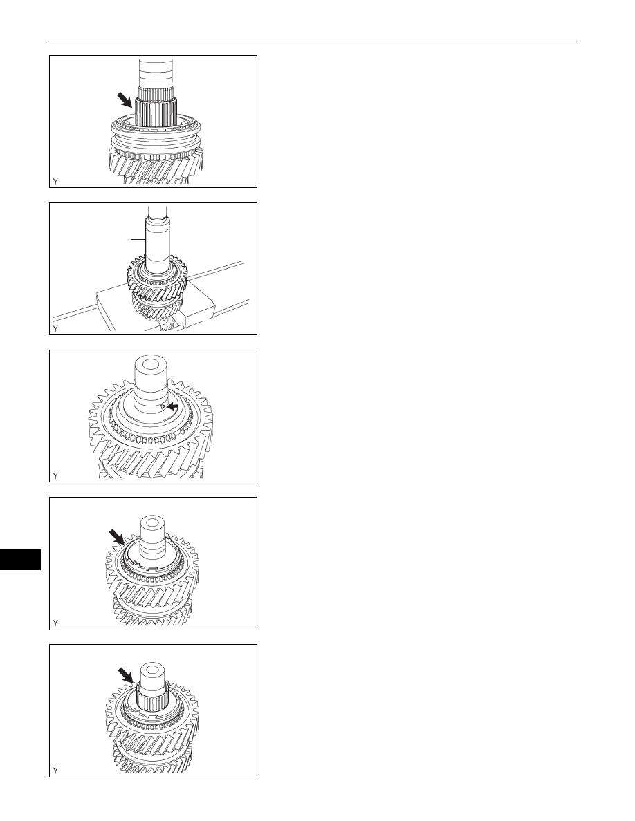
RA61F MANUAL TRANSMISSION – COUNTER GEAR AND REVERSE IDLER GEAR
MT
8.
INSTALL 1ST GEAR NEEDLE ROLLER BEARING
(a) Coat the 1st gear needle roller bearing with gear oil,
then install it onto the counter gear.
9.
INSTALL COUNTERSHAFT GEAR 1ST SPEED
(a) Coat the countershaft gear 1st speed with gear oil,
and install it onto the counter gear.
(b) Using SST and a press, install the reverse gear
spline piece.
SST
09309-37010
10. INSTALL BALL
(a) Install the ball into the counter gear.
11. INSTALL NO. 4 SYNCHRONIZER RING
(a) Coat the No. 4 synchronizer ring with gear oil, and
install it onto the counter gear.
12. INSTALL REVERSE GEAR NEEDLE ROLLER
BEARING
(a) Coat the reverse gear needle roller bearing with
gear oil, and install it onto the counter gear.
F051546E01
SST
F051561E01
F051544E01
F051543E01
F051542E01