Toyota FJ Cruiser (GSJ 10, 15 series). Instruction - part 431


  Index      Toyota     Toyota FJ Cruiser (model GSJ 10, 15 series) - service repair instruction 2007 year


Search            copyright infringement  


Content   ..  429  430  431  432   ..


Toyota FJ Cruiser (GSJ 10, 15 series). Instruction - part 431


MT–70

RA61F MANUAL TRANSMISSION  –  COUNTER GEAR AND REVERSE IDLER GEAR

MT

7.

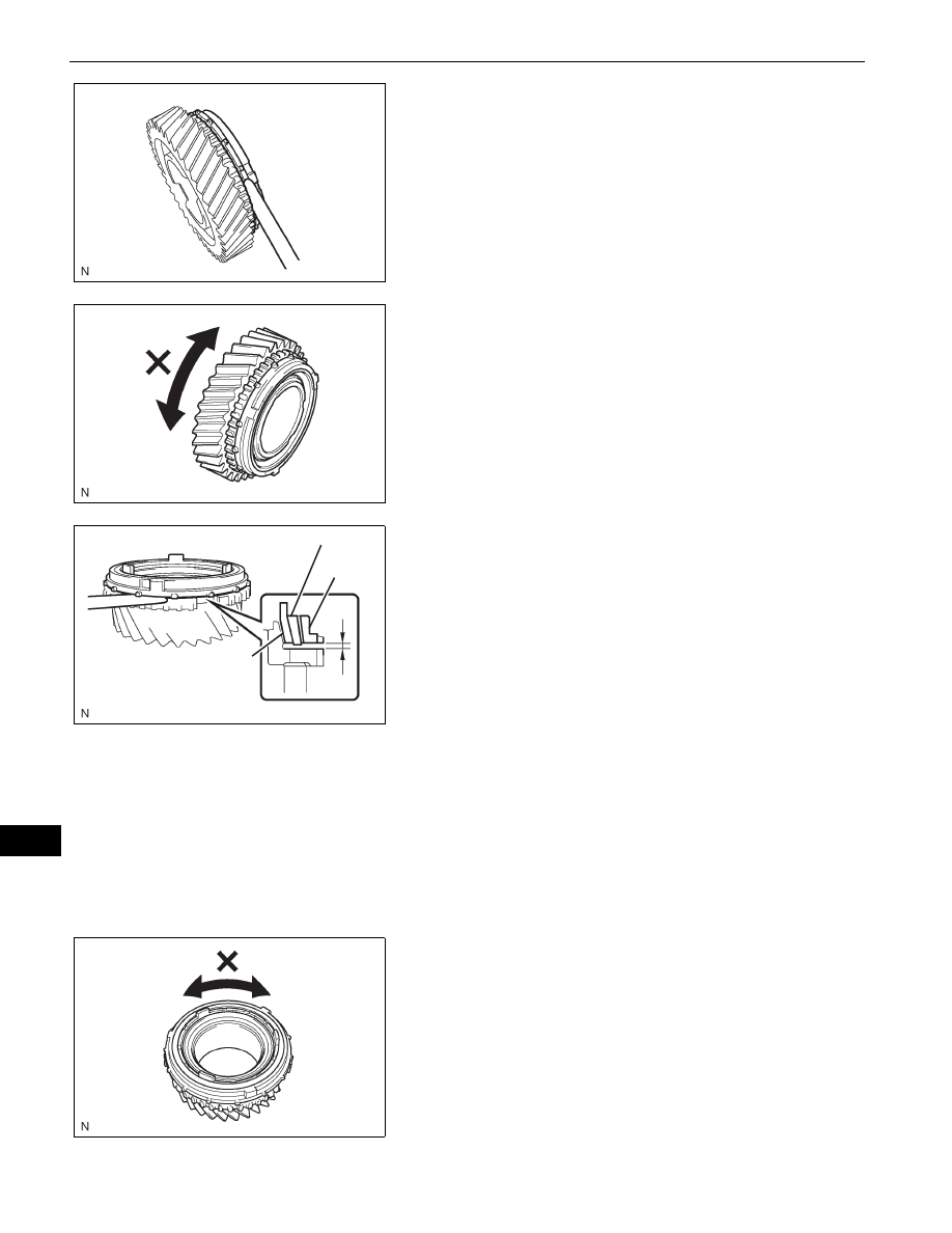
INSPECT NO. 4 SYNCHRONIZER RING
(a) Using a feeler gauge, measure the clearance 

between the synchronizer ring and reverse gear.
Standard clearance:

0.70 to 1.30 mm (0.0276 to 0.0512 in.)

Minimum clearance:

0.70 mm (0.0276 in.)

If the clearance is less than the minimum, replace 
the synchronizer ring.

(b) Coat the reverse gear cone with gear oil. Check the 

braking effect of the synchronizer ring. Turn the 
synchronizer ring in one direction while pushing it to 
the reverse gear cone. Check that the ring locks.

8.

INSPECT NO. 1 SYNCHRONIZER RING SET (FOR 
1ST GEAR)
(a) Using a feeler gauge, measure the clearance 

between the synchronizer ring and 1st gear.
Standard clearance:

Inner:

1.48 to 2.12 mm (0.0583 to 0.0835 in.)

Middle:

0.68 to 1.92 mm (0.0268 to 0.0756 in.)

Outer:

0.88 to 1.72 mm (0.0346 to 0.0677 in.)

Minimum clearance:

Inner:

1.48 mm (0.0583 in.)

Middle:

0.68 mm (0.0268 in.)

Outer:

0.88 mm (0.0346 in.)

If the clearance is less than the minimum, replace 
the synchronizer ring.

(b) Coat the 1st gear cone with gear oil. Check the 

braking effect of the synchronizer ring. Turn the 
synchronizer ring in one direction while pushing it to 
the 1st gear cone. Check that the ring locks.

F051636E01

D033665E01

Inner

Outer

Middle

F051638E01

F051639E01

RA61F MANUAL TRANSMISSION  –  COUNTER GEAR AND REVERSE IDLER GEAR

MT–71

MT

9.

INSPECT NO. 1 SYNCHRONIZER RING SET (FOR 
2ND GEAR)
(a) Using a feeler gauge, measure the clearance 

between the synchronizer ring and 2nd gear.
Standard clearance:

Inner:

1.48 to 2.12 mm (0.0583 to 0.0835 in.)

Middle:

0.68 to 1.92 mm (0.0268 to 0.0756 in.)

Outer:

0.88 to 1.72 mm (0.0346 to 0.0677 in.)

Minimum clearance:

Inner:

1.48 mm (0.0583 in.)

Middle:

0.68 mm (0.0268 in.)

Outer:

0.88 mm (0.0346 in.)

If the clearance is less than the minimum, replace 
the synchronizer ring.

(b) Coat the 2nd gear cone with gear oil. Check the 

braking effect of the synchronizer ring. Turn the 
synchronizer ring in one direction while pushing it to 
the 2nd gear cone. Check that the ring locks.

REASSEMBLY

1.

INSTALL RADIAL BALL BEARING INNER RACE
(a) Using SST and a press, install a new needle roller 

bearing inner race.
SST

09950-60010 (09951-00540)

2.

INSTALL SNAP RING COUNTER GEAR REAR 
BEARING
(a) Select a snap ring that will allow minimum axial play.

Standard clearance:

0.1 mm (0.004 in.) or less

Snap ring thickness

Inner

Outer

Middle

F051638E01

F051639E01

SST

F051640E01

D033689E01

Part No.

Thickness: mm (in.)

Mark

90520-31015

2.35 to 2.40

(0.0925 to 0.0945)

A

90520-31016

2.40 to 2.45

(0.0945 to 0.0965)

B

90520-31017

2.45 to 2.50

(0.0965 to 0.0984)

C

MT–72

RA61F MANUAL TRANSMISSION  –  COUNTER GEAR AND REVERSE IDLER GEAR

MT

(b) Using a snap ring expander, install the snap ring 

onto the counter gear.

3.

INSTALL NO. 1 TRANSMISSION CLUTCH HUB
(a) Apply a light coat of gear oil to the sleeve and hub.
(b) Install the clutch hub sleeve onto the clutch hub.
(c) Install the 3 shifting keys onto the clutch hub.
(d) Install the 3 shifting key springs onto the clutch hub.
(e) Place the ball in the hole in the shifting key, and 

install the hub sleeve while pushing in the ball.
NOTICE:
Prevent the ball from flying off.

4.

INSTALL 2ND GEAR NEEDLE ROLLER BEARING
(a) Coat the 2nd gear needle roller bearing with gear 

oil, then install it onto the counter gear.

90520-31018

2.50 to 2.55

(0.0984 to 0.1004)

D

90520-31019

2.55 to 2.60

(0.1004 to 0.1024)

E

90520-31020

2.60 to 2.65

(0.1024 to 0.1043)

F

90520-31021

2.65 to 2.70

(0.1043 to 0.1063)

G

90520-31022

2.70 to 2.75

(0.1063 to 0.1083)

H

90520-31023

2.75 to 2.80

(0.1083 to 0.1102)

J

90520-31024

2.80 to 2.85

(0.1102 to 0.1122)

K

90520-31025

2.85 to 2.90

(0.1122 to 0.1142)

L

90520-31033

2.90 to 2.95

(0.1142 to 0.1161)

M

Part No.

Thickness: mm (in.)

Mark

2nd Gear Side:

1st Gear Side:

F051641E01

F051551E01

RA61F MANUAL TRANSMISSION  –  COUNTER GEAR AND REVERSE IDLER GEAR

MT–73

MT

5.

INSTALL COUNTER SHAFT 2ND SPEED GEAR
(a) Coat the countershaft 2nd speed gear with gear oil, 

then install it onto the counter gear.

(b) Coat the No. 1 synchronizer ring set with gear oil, 

then install it onto the counter gear.

(c) Using SST and a press, install the No. 1 

transmission clutch hub onto the counter gear.
SST

09308-14010

HINT:
Align the convex portion of the synchronizer ring 
with the groove of the clutch hub.

(d) Install the clutch hub and confirm that the gear and 

synchronizer ring move smoothly.

6.

INSTALL CLUTCH HUB NO.1 SHAFT SNAP RING
(a) Select a snap ring that will allow minimum axial play.

Standard clearance:

0.1 mm (0.004 in.) or less

Snap ring thickness

(b) Using a snap ring expander, install the snap ring 

onto the counter gear.

7.

INSTALL NO. 1 SYNCHRONIZER RING SET (FOR 1ST 
GEAR)
(a) Coat the No. 1 synchronizer ring set with gear oil, 

then install it onto the counter gear.

SST

F051642E01

D033696E01

Part No.

Thickness: mm (in.)

Mark

90520-45013

2.28 to 2.33

(0.0898 to 0.0917)

A

90520-45014

2.33 to 2.38

(0.0917 to 0.0937)

B

90520-45015

2.38 to 2.43

(0.0937 to 0.0957)

C

90520-45016

2.43 to 2.48

(0.0957 to 0.0976)

D

90520-45017

2.48 to 2.53

(0.0976 to 0.0996)

E

90520-45018

2.53 to 2.58

(0.0996 to 0.1016)

F

90520-45019

2.58 to 2.63

(0.1016 to 0.1035)

G

F051547E01


Content   ..  429  430  431  432   ..