Toyota FJ Cruiser (GSJ 10, 15 series). Instruction - part 430
MT–66
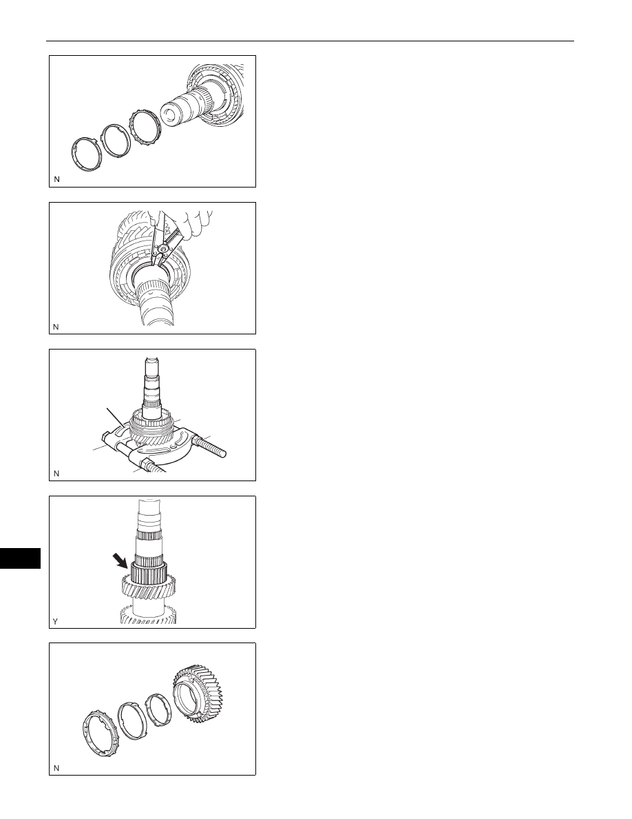
RA61F MANUAL TRANSMISSION – COUNTER GEAR AND REVERSE IDLER GEAR
MT
16. REMOVE NO. 1 SYNCHRONIZER RING SET (FOR
1ST GEAR)
(a) Remove the No. 1 synchronizer ring set from the
counter gear.
17. REMOVE CLUTCH HUB NO.1 SHAFT SNAP RING
(a) Using a snap ring expander, remove the snap ring
from the counter gear.
18. REMOVE COUNTER SHAFT 2ND SPEED GEAR
(a) Using a press, remove the counter shaft 2nd speed
gear together with the No. 1 transmission clutch hub
from the counter gear.
SST
09950-00020
19. REMOVE 2ND GEAR NEEDLE ROLLER BEARING
(a) Remove the 2nd needle roller bearing from the
counter gear.
20. REMOVE NO. 1 SYNCHRONIZER RING SET (FOR
2ND GEAR)
(a) Remove the No. 1 synchronizer ring set from the
2nd gear.
C136407
D033696E01
SST
F051632E01
F051551E01
F051633E01