Toyota FJ Cruiser (GSJ 10, 15 series). Instruction - part 120
1GR-FE ENGINE CONTROL SYSTEM – THROTTLE BODY
ES–429
ES
REMOVAL
1.
DISCONNECT CABLE FROM NEGATIVE BATTERY
TERMINAL
2.
DRAIN ENGINE COOLANT (See page
)
3.
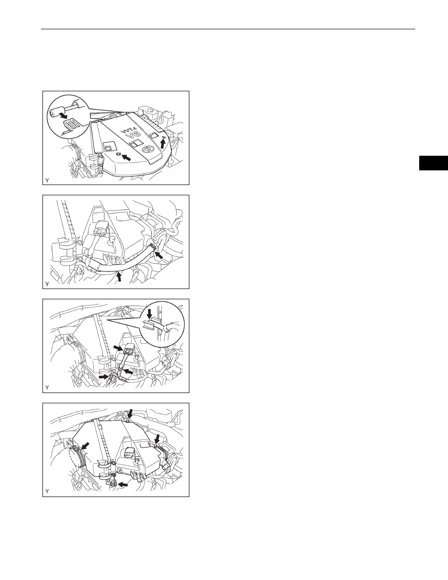
REMOVE V-BANK COVER
(a) Remove the 2 nuts, then remove the V-bank cover.
4.
REMOVE AIR CLEANER ASSEMBLY
(a) Disconnect the No. 2 ventilation hose.
(b) Disconnect the vacuum hose.
(c) Disconnect the mass air flow meter connector.
(d) Disengage the 2 wire harness clamps.
(e) Loosen the 2 hose clamps.
(f)
Remove the 2 bolts.
(g) Disconnect the air cleaner hose and remove the air
cleaner.
A126474
A075594E01
A075595E01
A075596E01