Toyota Sequoia (2005). Manual - part 885


  Главная      Automobile - Toyota     Toyota Sequoia - Repair manual 2005 year


поиск по сайту           правообладателям


содержание   ..  883  884  885  886   ..


Toyota Sequoia (2005). Manual - part 885


I18624

I18623

I18625

Wire Harness Side:

BODY ELECTRICAL

SEAT HEATER SYSTEM

BE–125

3529

3.

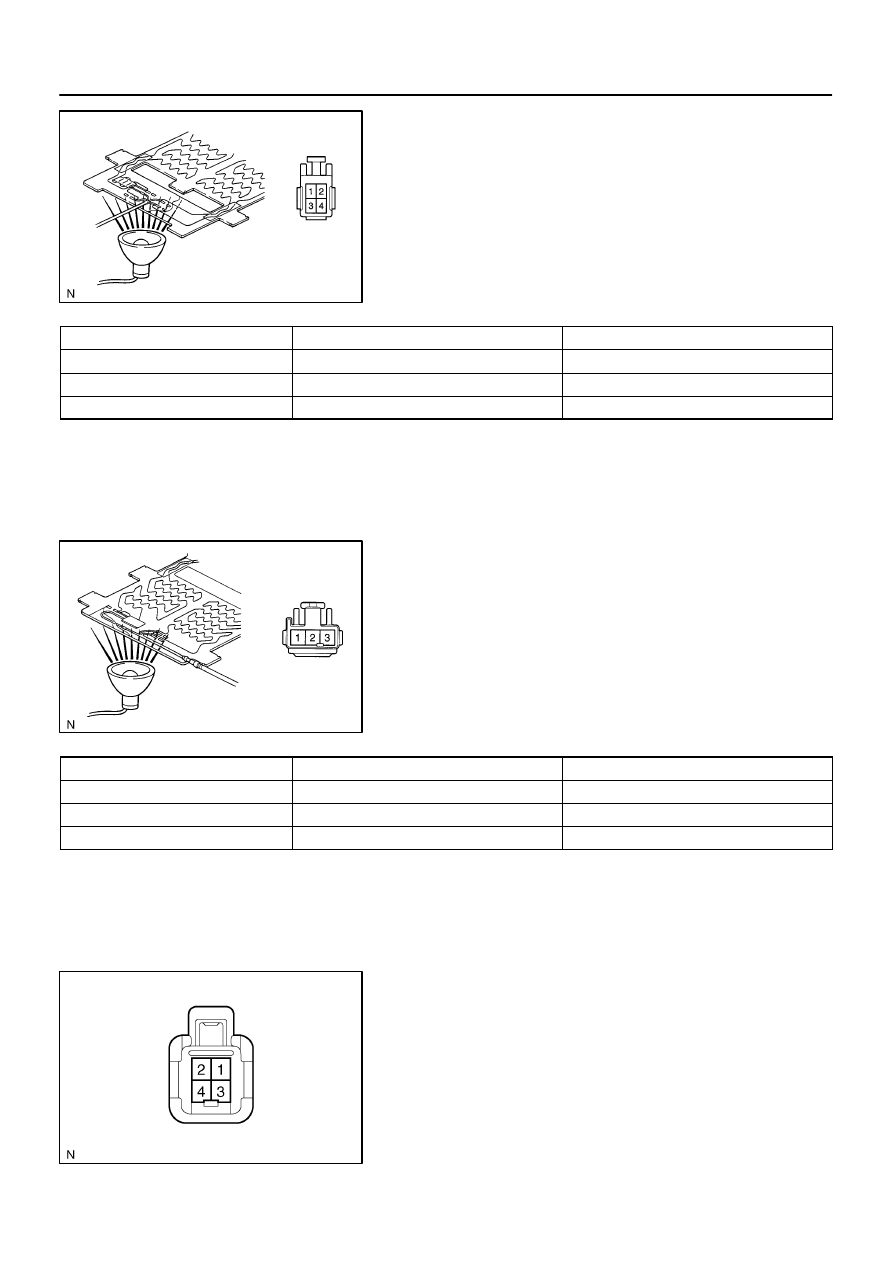
INSPECT SEAT HEATER CUSHION CONTINUITY

(a)

Heat the thermostat with a light.

(b)

Inspect the seat heater cushion continuity between termi-
nals, as shown.

Tester connection

Condition

Specified condition

2 – 4

Always

Continuity

1 – 3

Seat heater temperature below 30

°

C (86

°

F)

Continuity

1 – 3

Seat heater temperature above 40

°

C (104

°

F)

No continuity

If continuity is not as specified, replace the seat cushion pad.

4.

INSPECT SEAT BACK CONTINUITY

(a)

Heat the thermostat with a light.

(b)

Inspect the seat heater cushion continuity between termi-
nals, as shown.

Tester connection

Condition

Specified condition

2 – 3

Always

Continuity

1 – 2, 1 – 3

Seat heater temperature below 30

°

C (86

°

F)

Continuity

1 – 2, 1 – 3

Seat heater temperature above 50

°

C (122

°

F)

No continuity

If continuity is not as specified, replace the seat back pad.

5.

INSPECT SEAT HEATER CUSHION CIRCUIT

Inspect the seat heater inner cushion and front cushion continu-
ity between terminals, as shown.

I18626

Wire Harness Side:

I05027

1

2

3

5

1

2

3

5

BE–126

BODY ELECTRICAL

SEAT HEATER SYSTEM

3530

Tester connection

Condition

Specified condition

1 – Body ground

Seat heater switch ON

Battery positive voltage

If continuity is not as specified, replace the seat back pad.

6.

INSPECT SEAT BACK CONTINUITY

Inspect the seat back continuity between terminals, as shown.

Tester connection

Condition

Specified condition

1 – Body ground

Always

Continuity

If continuity is not as specified, replace the seat back pad.

7.

INSPECT SEAT HEATER RELAY CONTINUITY

Condition

Tester connection

Specified condition

Always

1 – 2

Continuity

Always

3 – 5

No continuity

Apply B+ between

terminals 1 and 2.

3 – 5

Continuity

If continuity is not as specified, replace the relay.

BE2MI–01

1

CLOCK WILL NOT OPERATE

I18689

Wire Harness Side:

B +

GND

Yes

Yes

No

No

Is there battery positive voltage between terminal +B and body
ground.

Is there continuity between terminal GND and body ground.

Replace clock (Integration Control and Panel).

Open or short circuit in wire harness between terminal
+B and DOME fuse.

Open circuit in wire harness between terminal
GND and body ground.

BODY ELECTRICAL

CLOCK

BE–127

3531

CLOCK

TROUBLESHOOTING

HINT:
Troubleshoot the clock according to the table below.

Problem

No.

Clock will not operate

1

Clock loses or gains time

2

Allowable error (per day): ±

 1.5 seconds

1.

PROBLEM NO. 1

(a)

Check that the battery positive voltage is 10 to 16 V.

If voltage is not as specified, replace the battery.
(b)

Check that the DOME fuse is not blown.

If the fuse is blown, replace the fuse and check for a short.
(c)

Troubleshoot the clock as follows.

HINT:
Inspect the connector on the wire harness side.

2

CLOCK LOSES OR GAINS TIME

I18689

Wire Harness Side:

B +

GND

Yes

Is there battery positive voltage between terminal +B and
body ground.

Adjust or replace clock.

Bellow 10 V

Locate cause and repair, or recharge battery.

BE–128

BODY ELECTRICAL

CLOCK

3532

2.

PROBLEM NO. 2

(a)

Check that the battery positive voltage is 10 to 16 V.

If voltage is not as specified, replace the battery.
(b)

Inspect the error of the clock.
Allowable error (per day): 

±

 1.5 seconds

If the error exceeds the allowable value, replace the clock.
(c)

Check that the clock adjusting button is struck and has
failed to return.

If the error exceeds the allowable value, replace the clock.
(d)

Troubleshoot the clock according to the following flow–
chart.

HINT:
Inspect the connector on the wire harness side.


содержание   ..  883  884  885  886   ..