содержание .. 864 865 866 867 ..
Toyota Sequoia (2005). Manual - part 866
BE2AV–04
I07176
Washer ON
OFF
INT
LO
HI
I01313
7
2
16
V03883
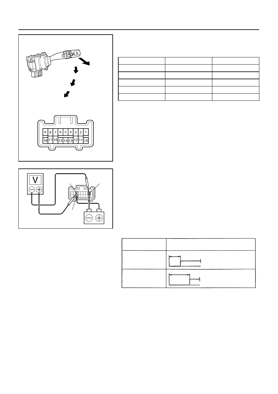
Voltage
INT time control
switch position
FAST
SLOW
Approx. 1–3 sec.
Battery positive voltage
0 volt
Approx. 10–15 sec.
Battery positive voltage
0 volt
–
BODY ELECTRICAL
WIPER AND WASHER SYSTEM
BE–49
3453
INSPECTION
1.
INSPECT FRONT WIPER AND WASHER SWITCH
CONTINUITY
Switch position
Tester connection
Specified condition
OFF
7 – 16
Continuity
INT
7 – 16
Continuity
LO
7 – 17
Continuity
HI
8 – 17
Continuity
Washer ON
2 – 11
Continuity
If continuity is not as specified, replace the switch.
2.
INSPECT FRONT WIPER INTERMITTENT OPERA-
TION
(a)
Turn the wiper switch to the INT position.
(b)
Turn the intermittent time control switch to the FAST posi-
tion.
(c)
Connect the positive (+) lead from the battery to terminal
16 and the negative (–) lead to terminal 2.
(d)
Connect the positive (+) lead from the voltmeter to termi-
nal 7 and the negative (–) lead to terminal 2, and check
that the meter needle indicates battery positive voltage.
If operation is not as specified, replace the wiper and washer
switch.