Toyota Tundra (2015 year). Manual - part 3118


  Index      Toyota     Toyota Tundra (2015 year) - Service and Repair Manual


Search            copyright infringement  


Content   ..  3116  3117  3118  3119   ..


Toyota Tundra (2015 year). Manual - part 3118


OK

NG

GO TO STEP 2

OK

PROCEED TO NEXT CIRCUIT INSPECTION SHOWN

IN PROBLEM SYMPTOMS TABLE

2.

INSPECT FUSE (MET-B)

(a) Remove the MET-B fuse from the engine room relay block unit B.

(b) Measure the resistance according to the value(s) in the table below.

Standard resistance:

TESTER CONNECTION

CONDITION

SPECIFIED CONDITION

MET-B fuse

Always

Below 1 Ω

NG

REPLACE FUSE

3.

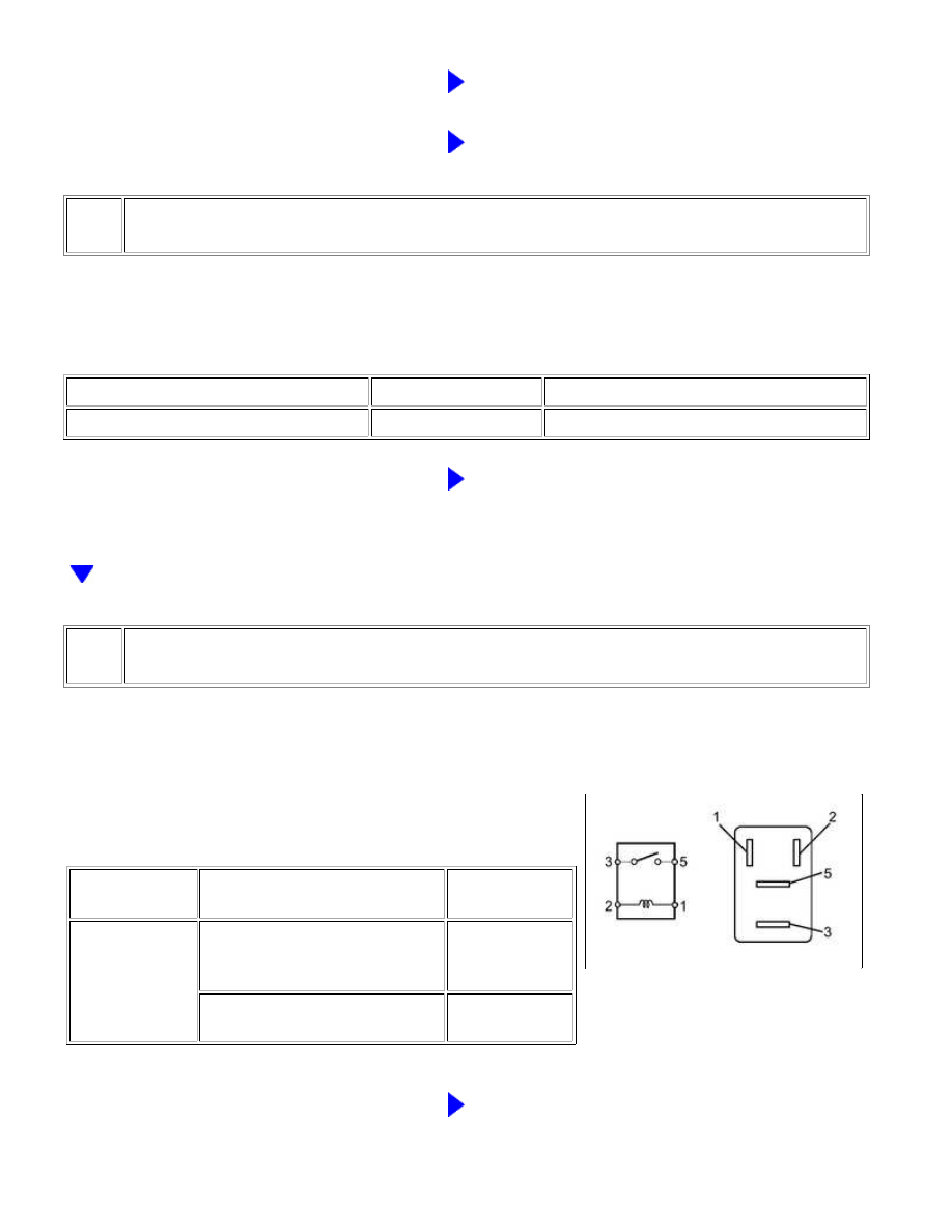
INSPECT SECURITY HORN RELAY

(a) Remove the SECURITY HORN relay from the engine room

relay block.

(b) Measure the resistance according to the value(s) in the table

below.

Standard resistance:

TESTER

CONNECTION

CONDITION

SPECIFIED

CONDITION

3 - 5

When battery voltage is not

applied between terminals 1 and

2

10 kΩ or higher

When battery voltage is applied

to terminals 1 and 2

Below 1 Ω

NG

REPLACE SECURITY HORN RELAY

THEFT DETERRENT: THEFT DETERRENT SYSTEM: Security Horn ...

OK

OK

4.

INSPECT SECURITY HORN ASSEMBLY

(a) Remove the security horn 


.

MEASUREMENT CONDITION

SPECIFIED CONDITION

Battery positive (+) → Terminal 1

Battery negative (-) → Horn bracket

Horn sounds

NG

REPLACE SECURITY HORN ASSEMBLY

5.

CHECK HARNESS AND CONNECTOR (SECURITY HORN RELAY - BATTERY)

(a) Remove the SECURITY HORN relay from the engine room

relay block.

THEFT DETERRENT: THEFT DETERRENT SYSTEM: Security Horn ...

OK

(b) Measure the voltage according to the value(s) in the table below.

Standard voltage:

TESTER CONNECTION

SWITCH

CONDITION

SPECIFIED

CONDITION

Engine room relay block security horn relay terminal 1 - Body

ground

Always

11 to 14 V

Engine room relay block security horn relay terminal 3 - Body

ground

Always

NG

REPAIR OR REPLACE HARNESS OR CONNECTOR

6.

CHECK HARNESS AND CONNECTOR (SECURITY HORN RELAY - SECURITY HORN)

(a) Remove the SECURITY HORN relay from the engine room

relay block.

(b) Disconnect the A28 security horn connector.

(c) Measure the resistance according to the value(s) in the table below.

Standard resistance:

THEFT DETERRENT: THEFT DETERRENT SYSTEM: Security Horn ...

OK

TESTER CONNECTION

CONDITION

SPECIFIED CONDITION

Engine room relay block security horn relay terminal 5 - A28-1

Always

Below 1 Ω

NG

REPAIR OR REPLACE HARNESS OR CONNECTOR

7.

CHECK HARNESS AND CONNECTOR (MAIN BODY ECU - SECURITY HORN RELAY)

(a) Remove the SECURITY HORN relay from the engine room

relay block.

(b) Disconnect the J1 main body ECU connector.

(c) Measure the resistance according to the value(s) in the table below.

Standard resistance:

TESTER CONNECTION

CONDITION

SPECIFIED CONDITION

Engine room relay block security horn relay terminal 2 - J1-6 (SH)

Always

Below 1 Ω

NG

REPAIR OR REPLACE HARNESS OR CONNECTOR

OK

REPLACE MAIN BODY ECU

THEFT DETERRENT: THEFT DETERRENT SYSTEM: Security Horn ...


Content   ..  3116  3117  3118  3119   ..