Content .. 3025 3026 3027 3028 ..
Toyota Tundra (2015 year). Manual - part 3027
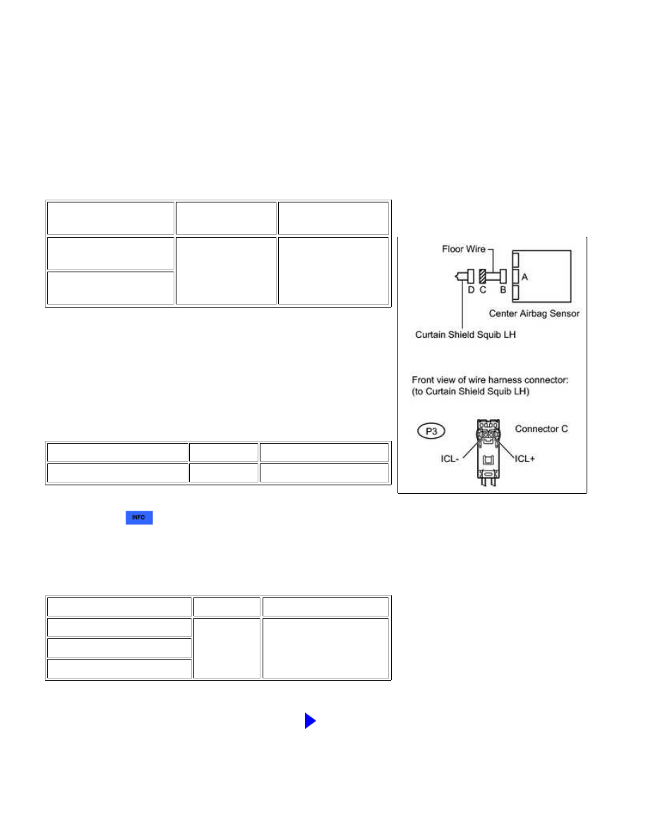
(a) Disconnect the connectors from the center airbag sensor.
(b) Connect the negative (-) terminal cable to the battery, and
wait for at least 2 seconds.
(c) Turn the ignition switch to ON.
(d) Measure the voltage according to the value(s) in the table
below.
Standard voltage:
TESTER CONNECTION
SWITCH
CONDITION
SPECIFIED
CONDITION
P3-1 (ICL-) - Body
ground
Ignition switch ON
Below 1 V
P3-2 (ICL+) - Body
ground
(e) Turn the ignition switch off.
(f) Disconnect the negative (-) terminal cable from the battery,
and wait for at least 90 seconds.
(g) Measure the resistance according to the value(s) in the
table below.
Standard resistance:
TESTER CONNECTION
CONDITION
SPECIFIED CONDITION
P3-1 (ICL-) - P3-2 (ICL+)
Always
Below 1 Ω
(h) Release the activation prevention mechanism built into
connector B
.
(i) Measure the resistance according to the value(s) in the table
below.
Standard resistance:
TESTER CONNECTION
CONDITION
SPECIFIED CONDITION
P3-1 (ICL-) - P3-2 (ICL+)
Always
1 MΩ or higher
P3-1 (ICL-) - Body ground
P3-2 (ICL+) - Body ground
NG
REPLACE FLOOR WIRE
SUPPLEMENTAL RESTRAINT SYSTEM: AIRBAG SYSTEM: B1830/...