Content .. 3022 3023 3024 3025 ..
Toyota Tundra (2015 year). Manual - part 3024
OK
(k) Release the activation prevention mechanism built into
connector B
.
(l) Measure the resistance according to the value(s) in the table
below.
Standard resistance:
TESTER CONNECTION
CONDITION
SPECIFIED CONDITION
P12-1 (SFL+) - P12-2 (SFL-)
Always
1 MΩ or higher
P12-1 (SFL+) - Body ground
P12-2 (SFL-) - Body ground
NG
REPLACE FLOOR WIRE
3.
CHECK CENTER AIRBAG SENSOR
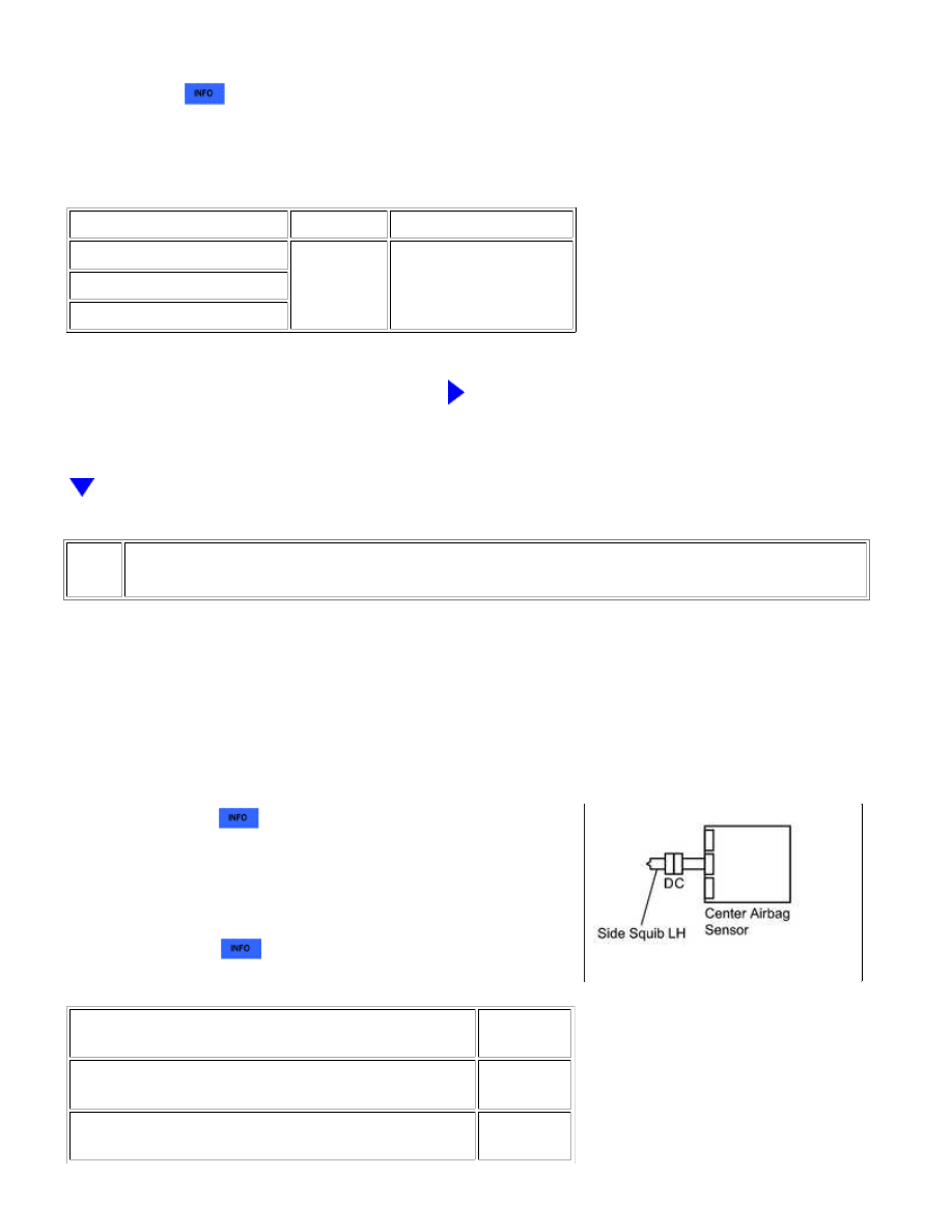
(a) Connect the connectors to the front seat side airbag LH and
the center airbag sensor.
(b) Connect the negative (-) terminal cable to the battery, and
wait for at least 2 seconds.
(c) Turn the ignition switch to ON, and wait for at least 60
seconds.
(d) Clear the DTCs
.
(e) Turn the ignition switch off.
(f) Turn the ignition switch to ON, and wait for at least 60
seconds.
(g) Check for DTCs
.
Result
RESULT
PROCEED
TO
DTC B1820, B1821, B1822 or B1823 is output (for
Column Shift Type)
A
DTC B1820, B1821, B1822 or B1823 is output (for Floor
Shift Type)
B
SUPPLEMENTAL RESTRAINT SYSTEM: AIRBAG SYSTEM: B1820/...