Subaru Legacy (2023 year). Manual in english - page 34
 

  Index      Manuals     Subaru Legacy (2023 year). Manual in english


Search            copyright infringement  


Content      ..     32      33      34      35     ..


Subaru Legacy (2023 year). Manual in english - page 34


(542,1)

11-17. Alloy Wheels

Alloy wheels can be scratched and da-
maged easily. Handle them carefully to
maintain their appearance, performance,
and safety.

.

When any of the wheels is removed and

replaced for tire rotation or to change a flat,
always check the tightness of the wheel
nuts after driving approximately 600 miles
(1,000 km). If any nut is loose, tighten it to
the specified torque.

.

Never apply oil to the threaded parts,

wheel nuts, or tapered surface of the
wheel.

.

Never let the wheel rub against sharp

protrusions or curbs.

.

When wheel nuts, balance weights, or

the center cap is replaced, be sure to
replace them with genuine SUBARU parts
designed for alloy wheels.

11-18. Windshield Washer
Fluid

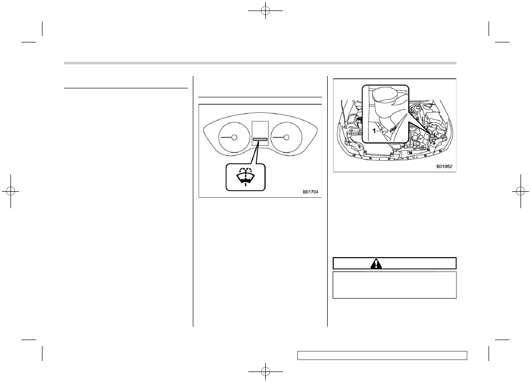
Windshield washer fluid warning light

When there is only a small amount of
washer fluid remaining, the windshield
washer fluid warning light will appear.
When this occurs, refill the washer fluid
as follows.

1)

“FULL” mark

Remove the washer tank filler cap, then
add fluid until it reaches the “FULL” mark
on the tank.
Use windshield washer fluid. If windshield
washer fluid is unavailable use clean
water.
In areas where water freezes in winter, use
an anti-freeze type windshield washer
fluid.

CAUTION

Never use engine coolant as washer
fluid because it could cause paint
damage.

If you fill the windshield washer tank with a
fluid with a different concentration from the

Alloy Wheels

540

(543,1)

one used previously, purge the old fluid
from the piping between the windshield
washer tank and washer nozzles by
operating the washer for a certain period
of time. Otherwise, if the concentration of
the fluid remaining in the piping is too low
for the outside temperature, it may freeze
and block the nozzles.

CAUTION

.

Adjust the washer fluid concen-

tration appropriately for the out-
side temperature. If the concen-
tration is inappropriate, sprayed
washer fluid may freeze on the
windshield and obstruct your
view, and the fluid may freeze in
the windshield washer tank.

.

State or local regulations on

volatile organic compounds may
restrict the use of methanol, a
common windshield washer anti-
freeze additive. Washer fluids
containing non-methanol anti-
freeze agents should be used
only if they provide cold weather
protection without damaging
your vehicle’s paint, wiper blades
or washer system.

11-19. Replacement of Wiper
Blades

Grease, wax, insects, or other material on
the windshield or the wiper blade results in
jerky wiper operation and streaking on the
glass. If you cannot remove the streaks
after operating the windshield washer or if
the wiper operation is jerky, clean the outer
surface of the windshield and rear window
using a sponge or soft cloth with a neutral
detergent or mild-abrasive cleaner. Do not,
however, use detergent to clean the blade
rubbers. Use only a sponge or soft cloth
(and no neutral detergent or mild abrasive
cleaner) when you clean the blade rub-
bers. If you wipe the rubber of the blade
strongly, the black coating component will
peel off, which will cause the wiper to
judder. Also, after wiping it off, check that
the rubber has not come loose. After
cleaning the window glass and wiper blade
rubbers, be sure to rinse them with clean
water. Rinse the window until the water
does not form beads on the glass. This
indicates that the glass is clean.

CAUTION

.

Do not clean the wiper blades

with gasoline or a solvent, such
as paint thinner or benzine. This

will cause deterioration of the
wiper blades.

.

When you wish to raise the pas-

senger-side wiper arm, first raise
the driver-side wiper arm. Other-
wise, the passenger-side wiper
assembly and driver-side wiper
assembly will touch each other,
possibly resulting in scratches.

.

Return the passenger-side wiper

arm to its original position before
returning the driver-side wiper
arm to its original position. Other-
wise, the passenger-side wiper
assembly and driver-side wiper
assembly will touch each other,
possibly resulting in scratches.

.

When returning the raised wipers

to the original positions, return
the wipers slowly on the wind-
shield by hand. Returning the
wipers from the detached posi-
tions by the spring operation
might change the shape of the
wiper arm or scratch the wind-
shield.

.

While removing the wiper blades

from the wiper arms, do not
return the wiper arms to the
original positions. Otherwise,
the windshield surface may be

– CONTINUED –

Replacement of Wiper Blades

541

11

Maintenance

and

Service

(544,1)

scratched.

If you cannot eliminate the streaking even
after following this method, replace the
wiper blades using the following proce-
dures.

&

Windshield Wiper Blade As-
sembly

NOTE

Do not lower the wiper arm while the
wiper blade assembly is removed.

1. Raise the wiper arm off the windshield.
First raise the driver’s side wiper arm and
then raise the front passenger’s side wiper
arm.

CAUTION

Hold the wiper arm when replacing
the wiper blade. Holding the wiper
blade, may result in blade deforma-
tion.

1)

Lock knob

2. Hold the wiper blade connection by
hand, push the lock knob to release the
lock, and then pull out the wiper blade
assembly.

NOTE

Do not use a hard object to push the
lock knob. The lock knob may be
scratched.

3. When installing the wiper blade as-
sembly, align it with the wiper arm connec-
tion part and then slide it in the opposite
direction of removal to install. After instal-
ling the wiper blade assembly, check that
the connection part is locked completely.
4. Hold the wiper arm by hand and slowly
lower it in position.

Replacement of Wiper Blades

542

(545,1)

&

Window Wiper Blade Rubber

Replace the wiper blade rubber according
to the following procedure.
1. Pull the wiper blade rubber until the slit
on the underside of the wiper blade is in
the removal position, as shown in the

illustration, so that it can be removed.
2. Pull the end of the wiper blade rubber
through the slit to remove it.
3. To install a new wiper blade rubber,
perform the removal procedure in the
reverse order. After installation, check that
the tip of the wiper rubber has reached the
end of the cap.

NOTE

It may be difficult to perform the wiper
blade rubber replacement. We recom-
mend that you contact your SUBARU
dealer for wiper blade rubber replace-
ment if necessary.

&

Rear Window Wiper Blade
Assembly (Outback/Subaru
Outback Wilderness)

1. Raise the wiper arm off the rear
window.

2. Turn the wiper blade assembly coun-
terclockwise.

– CONTINUED –

Replacement of Wiper Blades

543

11

Maintenance

and

Service

(546,1)

3. Pull the wiper blade assembly toward
you to remove it from the wiper arm.

&

Rear Window Wiper Blade
Rubber (Outback/Subaru
Outback Wilderness)

1. Pull out the end of the blade rubber
assembly to unlock it from the plastic
support.

2. Pull the blade rubber assembly out of
the plastic support.

1)

Metal spines

3. If the new blade rubber is not provided
with two metal spines, remove the metal
spines from the old blade rubber and install

Replacement of Wiper Blades

544

(547,1)

them in the new blade rubber.

4. Align the claws of the plastic support
with the grooves in the blade rubber
assembly, then slide the blade rubber
assembly into place.

Securely retain both ends of the rubber
with the stoppers on the plastic support
ends. If the rubber is not retained properly,
the wiper may scratch the rear window
glass.
5. Install the wiper blade assembly to the
wiper arm. Make sure that it locks in place.
6. Hold the wiper arm by hand and slowly
lower it in position.

11-20. Battery

WARNING

.

Before beginning work on or near

any battery, be sure to extinguish
all cigarettes, matches, and light-
ers. Never expose a battery to an
open flame or electric sparks.
Batteries give off a gas which is
highly flammable and explosive.

.

For safety, in case an explosion

does occur, wear eye protection
or shield your eyes when working
near any battery. Never lean over
a battery.

.

Do not let battery fluid contact

eyes, skin, fabrics, or paint be-
cause battery fluid is a corrosive
acid. If battery fluid gets on your
skin or in your eyes, immediately
flush the area with water thor-
oughly. Seek medical help imme-
diately if acid has entered the
eyes.

If battery fluid is accidentally
swallowed, immediately drink a
large amount of milk or water,
and seek medical attention im-
mediately.

– CONTINUED –

Battery

545

11

Maintenance

and

Service

(548,1)

.

To lessen the risk of sparks,

remove rings, metal watchbands,
and other metal jewelry. Never
allow metal tools to contact the
positive battery terminal and any-
thing connected to it WHILE you
are at the same time in contact
with any other metallic portion of
the vehicle because a short cir-
cuit will result.

.

Keep everyone including children

away from the battery.

.

Charge the battery in a well-

ventilated area.

.

Battery posts, terminals, and re-

lated accessories contain lead
and lead compounds, chemicals
known to the State of California
to cause cancer and reproductive
harm. Batteries also contain
other chemicals known to the
State of California to cause can-
cer. Wash hands after handling.

CAUTION

Never use more than 10 amperes
when charging the battery because
it will shorten battery life.

It is unnecessary to periodically check the
battery fluid level or periodically refill with
distilled water.

11-21. Fuses

CAUTION

Never replace a fuse with one having
a higher rating or with material other
than a fuse because serious damage
or a fire could result.

NOTE

Fuse rating and using circuit are de-
scribed on each behind the fuse box
cover.

The fuses are designed to melt during an
overload to prevent damage to the wiring
harness and electrical equipment. The
fuses are located in two fuse boxes.

Fuses

546

(549,1)

One is located under the instrument panel
behind the fuse box cover on the driver’s
seat side. To remove the cover, pull it out.

1)

Spare fuses

2)

Fuse puller

The other one (main fuse box) is housed in
the engine compartment. Also, the spare
fuses and fuse puller are stored in the fuse
box cover.
Pinch the upper part of the fuse puller
when removing it from the main fuse box.

1)

Good

2)

Blown

If any lights, accessories or other electrical
controls do not operate, inspect the corre-
sponding fuse. If a fuse has blown, replace
it.
1. Turn the ignition switch to the “LOCK”/
“OFF” position and turn off all electrical
accessories.
2. Remove the fuse box cover.
3. Determine which fuse may be blown.
Look at the back side of each fuse box
cover.

4. Pull out the fuse with the fuse puller.
5. Inspect the fuse. If it has blown,
replace it with a spare fuse of the same
rating.
6. If the same fuse blows again, this
indicates that its system has a problem.
Contact your SUBARU dealer for repairs.

Fuses

547

11

Maintenance

and

Service

(550,1)

11-22. Installation of Acces-
sories

Always consult your SUBARU dealer
before installing fog lights or any other
electrical equipment in your vehicle. Such
accessories may cause the electronic
system to malfunction if they are incor-
rectly installed or if they are not suited for
the vehicle. We recommend that you
install only genuine SUBARU accessories
on your vehicle.

11-23. Replacing Bulbs

WARNING

Bulbs may become very hot while
illuminated. Before replacing bulbs,
turn off the lights and wait until the
bulbs cool down, Otherwise, there is
the risk of sustaining a burn injury.

CAUTION

Replace any bulb only with a new
bulb of the specified wattage. Using
a bulb of different wattage could
result in a fire. For the specified
wattage of each bulb, refer to “Bulb
Chart”

P568. For replacement,

contact your SUBARU dealer.

&

Headlights

The LED headlight warning light illumi-
nates if the LED headlights malfunction.
Have your vehicle inspected at a SUBARU
dealer as soon as possible.

Installation of Accessories

548

(551,1)

&

Front Turn Signal Light/Front
Position Light

Right-hand side (Legacy/Outback)

R i g h t - h a n d s i d e ( S u b a r u O u t b a c k
Wilderness)

Left-hand side (Legacy/Outback)

L e f t - h a n d s i d e ( S u b a r u O u t b a c k
Wilderness)

1. Turn the socket counterclockwise and
pull it out.

2. Pull out the bulb from the socket and
replace the bulb with a new one.

&

Rear Combination Lights

!

Legacy

NOTE

It may be difficult to replace the bulbs.
We recommend that you have the bulbs
replaced by your SUBARU dealer if
necessary.

1. Undo the clips. For the method to undo
the clips, refer to “Type C clips”

P516.

– CONTINUED –

Replacing Bulbs

549

11

Maintenance

and

Service

(552,1)

2. Remove the side cover.

3. Remove the upper and lower screws.

4. Slide the rear combination light as-
sembly straight rearward and remove it
from the vehicle.

1)

Rear turn signal light

5. Remove the bulb holder from the rear
combination light assembly by turning it

counterclockwise.
6. Pull the bulb out of the bulb holder and
replace it with a new one.
7. Set the bulb holder into the rear
combination light assembly and turn it
clockwise until it locks.

8. Reinstall the rear combination light
assembly by sliding the two-pronged part
of the combination light assembly securely
to each holder of the vehicle side.

Replacing Bulbs

550

(553,1)

9. Tighten the upper and lower screws.
10. Reinstall the side cover.

!

Outback/Subaru Outback
Wilderness

1. Undo the clips. For the method to undo

the clips, refer to “Type C clips”

P516.

2. Remove the side cover.

3. Remove the upper and lower screws.

4. Slide the rear combination light as-
sembly straight rearward and remove it
from the vehicle.

1)

Rear turn signal light

2)

Rear side marker light

5. Remove the bulb holder from the rear

– CONTINUED –

Replacing Bulbs

551

11

Maintenance

and

Service

(554,1)

combination light assembly by turning it
counterclockwise.
6. Pull the bulb out of the bulb holder and
replace it with a new one.
7. Set the bulb holder into the rear
combination light assembly and turn it
clockwise until it locks.

8. Reinstall the rear combination light
assembly by sliding the two-pronged part
of the combination light assembly securely
to each holder of the vehicle side.

9. Tighten the upper and lower screws.
10. Reinstall the side cover.

&

Backup Light

!

Legacy

NOTE

It may be difficult to replace the bulbs.
We recommend that you have the bulbs
replaced by your SUBARU dealer if
necessary.

1. Open the trunk.

2. Remove the trunk trim lining by remov-
ing the clips indicated in the illustration.

3. Turn the bulb socket counterclockwise
and remove it.
4. Pull the bulb out of the bulb socket and
replace it with a new one.

Replacing Bulbs

552

(555,1)

5. Install the bulb socket by turning it
clockwise.
6. Reconnect the electrical connector.
7. Reinstall the trunk trim lining.

!

Outback/Subaru Outback
Wilderness

1. Apply a flat-head screwdriver to the
light cover or rear gate light (if equipped)
as shown in the illustration, and pry the
light cover off from the rear gate trim.

2. Turn the bulb socket counterclockwise
and remove it.

3. Pull the bulb out of the bulb socket and
replace it with a new one.
4. Install the bulb socket by turning it
clockwise.

5. Install the light cover on the rear gate.

&

Door Step Light

CAUTION

Replacing the bulb could cause a
short circuit. Have the bulb replaced
by your SUBARU dealer.

&

Trunk Light (Legacy)

CAUTION

Replacing the bulb could cause
burns since the bulb may be very
hot. Have the bulb replaced by your
SUBARU dealer.

&

Other Bulbs

It may be difficult to replace the bulbs.
We recommend that you have the bulbs
replaced by your SUBARU dealer if
necessary.

– CONTINUED –

Replacing Bulbs

553

11

Maintenance

and

Service

(556,1)

&

Adjusting Headlight Aim
(Legacy/Outback)

1)

Adjustment screw A

2)

Adjustment screw B

!

Before checking the headlight aim-
ing

1. Make sure the vehicle has a full tank of
gasoline and the area around the headlight
is not deformed.
2. Park the vehicle on level ground.
3. Sit in the driver’s seat.
4. Bounce the vehicle several times.

!

Headlight aim adjustment

1)

Adjustment direction mark

1. Turn screw A clockwise or counter-
clockwise to adjust it.
Remember the direction of the rotation and
number of rotations.

1)

Adjustment direction mark

2. Turn screw B the same number of turns
and in the same direction as step 1.

NOTE

.

If the headlight aim cannot be ad-

justed, contact your SUBARU dealer.

.

To inspect the headlight aim posi-

tion, consult a SUBARU dealer.

Replacing Bulbs

554

(557,1)

11-24. Replacing Battery

The access key fob/transmitter battery
may be discharged under the following
conditions.

.

The operation of the keyless access

function is unstable.

.

The operating distance of the remote

keyless entry system is unstable.

.

The transmitter does not operate prop-

erly when used within the standard dis-
tance.

Replace the battery with a new one.

CAUTION

.

Do not let dust, oil or water get on

or in the access key fob/transmit-
ter when replacing battery.

.

Be careful not to damage the

printed circuit board in the ac-
cess key fob/transmitter when
replacing the battery.

.

Be careful not to allow children to

touch the battery and any re-
moved parts; children could
swallow them.

.

There is a danger of an explosion

if the battery is incorrectly re-
placed. Replace only with the

same or equivalent type of the
battery.

.

Batteries shall not be exposed to

excessive heat such as bright
sunlight, fire or the like.

NOTE

.

Replace only with the same or

equivalent type of battery recom-
mended by the manufacturer.

.

Dispose of used batteries according

to the local laws.

.

Mount the battery in the correct

orientation to prevent fluid leakage.
Be careful not to bend the terminals. It
may result in a malfunction.

.

It is recommended that the battery

should be replaced by a SUBARU deal-
er.

.

Use a new battery.

.

After replacing the battery, confirm

that the access key fob/transmitter
functions properly.

&

Replacing Battery of Access
Key Fob

CAUTION

.

When removing or fitting the

access key fob cover, make sure
that the plastic part does not
come off or become misaligned.

.

Before replacing the battery, re-

move any static electricity.

Battery: Button battery CR2032 or
equivalent

1)

Release button

2)

Emergency key

1. Take out the emergency key.

– CONTINUED –

Replacing Battery

555

11

Maintenance

and

Service


Content      ..     32      33      34      35     ..