Subaru Legacy (2023 year). Manual in english - page 17
 

  Index      Manuals     Subaru Legacy (2023 year). Manual in english


Search            copyright infringement  


Content      ..     15      16      17      18     ..


Subaru Legacy (2023 year). Manual in english - page 17


(262,1)

&

High Beam Assist Function

NOTE

.

The high beam assist function uti-

lizes the stereo camera installed at the
position of the front map lights.

.

For details on how to handle the

stereo camera, refer to the Owner’s
Manual supplement for the EyeSight
system.

The high beam assist function automati-
cally changes the headlight from high
beam to low beam (or vice versa).

When all of the following conditions are
met, the headlight will change to high
beam.

.

When the vehicle speed increases to or

above 20 mph (32 km/h).

.

There is no preceding or oncoming

vehicle.

.

The forward area of the vehicle is dark.

.

The road does not have a sharp curve.

When any of the following conditions are
met, the headlight will change to low beam.

.

When the vehicle speed decreases to

or below 10 mph (16 km/h).

.

When the forward area of the vehicle is

bright.

.

When there is a preceding or oncoming

vehicle.

.

When the EyeSight system is malfunc-

tioning or is temporarily stopped.

NOTE

.

Do not overestimate the capacity of

the high beam assist function. The
driver always has the responsibility to
understand the surrounding situation,
to drive safely, and to change the
headlight mode manually if necessary.

.

The factory setting (default setting)

for this function is set as “operational”.
This setting can be changed to OFF
(non-operation) at SUBARU dealers.
For more details, contact a SUBARU
dealer.

!

How to use the high beam assist
function

The high beam assist function will be
activated when all the following conditions
are met.

.

The light control switch is in the “AUTO”

position and the low beam headlights are
on automatically.

.

The turn signal lever is pushed forward.

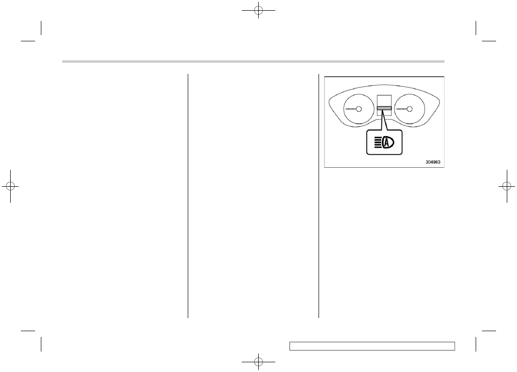
High beam assist indicator

When the high beam assist function is
activated, the high beam assist indicator
on the combination meter will illuminate.

NOTE

If the high beam assist function is
malfunctioning or is temporarily
stopped, the headlight will be fixed at
low beam.

!

How to temporarily lower the sensi-
tivity of the high beam assist func-
tion

The sensitivity of the high beam assist
function can be lowered by using the
following operations.
1. Before turning the ignition switch to the
“ON” position, set the light control switch to

Light Control Switch

260

(263,1)

the “AUTO” position and push the signal
lever forward (high beam position).
2. Turn the ignition switch to the “ON”
position and within approximately 15 sec-
onds, press the “

/

” (following distance

setting) switch more than 10 times con-
secutively.

When the sensitivity of the high beam
assist function is lowered, the high beam
assist indicator light “

” on the combina-

tion meter display (color LCD) will flash.

NOTE

.

The sensitivity of the high beam

assist function cannot be lowered in
the following conditions.

– Cruise control indicator is illumi-
nated.
– The EyeSight warning indicator
(yellow) is illuminated.

.

The sensitivity of the high beam

assist function returns to normal level
the next time the ignition switch is
turned to the “LOCK”/“OFF” position
and the engine is restarted.

!

How to change the headlight mode
manually

Change to the low beam:

When you return the turn signal lever to the
center position, the high beam assist

function will turn off and the high beam
assist indicator will turn off.

Change to the high beam:

When you turn the light control switch to
the “

” position, the headlight mode will

be changed to the high beam.
At this time, the high beam assist function
will turn off, the high beam assist indicator
will turn off and the high beam indicator
light will turn on.

NOTE

.

After manually changing the head-

light mode to the high beam, if you turn
on the high beam assist function,
return the light control switch to the
“AUTO” position.

.

When manually changing the head-

light mode to the high beam, if you turn
the light control switch to the “

position, the parking lights, front side
marker lights, rear side marker lights,
tail lights and license plate lights will
turn on.

!

Tips for the high beam assist sys-
tem

.

The high beam assist function recog-

nizes the condition surrounding the vehicle
based on the brightness of illumination
ahead of your vehicle, etc. Therefore, the
headlight mode may switch in some

situations that do not match to the driver’s
sense.

.

A bicycle or cargo cycle may not be

detected.

.

Under the following situations, the

brightness of ambient illumination may
not be detected correctly and the high
beam assist function may not work prop-
erly. As a result, the glare of the high beam
may disturb the oncoming vehicle or
vehicle ahead. Also, the low beam mode
may continue although there are no
oncoming vehicles and vehicles ahead.
In the such cases, change the headlight
mode manually.

– In bad weather (fog, snow, sand
storm, heavy rain, etc.).
– When the windshield glass is dirty or
fogged.
– When the windshield is cracked or
damaged.
– If there are lights similar to the
headlights or the tail lights in the
surrounding area.
– When an oncoming vehicle or ve-
hicle ahead is driven without its head-
lights and tail lights on.
– If the headlights of an oncoming
vehicle or the tail lights of a vehicle
ahead are dirty or discolored, or if the
light beams are not aimed correctly.
– When a rapid change of brightness

– CONTINUED –

Light Control Switch

261

3

Instruments

and

Controls

(264,1)

continues while driving.
– When driving on a road with many
ups and downs or uneven surfaces.
– When driving on a road with many
curves.
– When there are some objects that
reflect light strongly, such as a road
sign or a mirror in vehicle ahead.
– When the rear part of the vehicle
ahead, such as a container, reflects
light strongly.
– When the headlights of your vehicle
are damaged or dirty.
– When your vehicle is tilted, such as
in case the vehicle has a flat tire or is
being towed.
– When the stereo camera is de-
formed or the stereo camera lenses
are dirty.
– Immediately after the engine has
started.

.

In the following conditions, the head-

light mode will not be automatically chan-
ged from the high beam to the low beam.

– When your vehicle passes an on-
coming vehicle suddenly in a blind
curve.
– When another vehicle passes in
front of your vehicle.
– When an oncoming vehicle or ve-
hicle ahead comes in and out of view
because of continuous curves, median

strips, roadside trees, etc.

.

If the stereo camera detects the light of

the front fog lights of an oncoming vehicle,
the headlight mode may change from the
high beam to the low beam automatically.

.

The headlight mode may change from

the high beam to the low beam, or the low
beam mode may continue, when affected
by a street light, traffic signal, illumination
of an advertisement board, or a reflective
object such as a road sign and signboard.

.

The timing of the change of headlight

mode may differ due to the following
factors.

– Color or brightness of the headlights
of an oncoming vehicle or the tail lights
of a vehicle ahead.
– The headlights of the oncoming
vehicle or the tail lights of the vehicle
ahead are covered with mud, snow,
etc.
– Movement and direction of an on-
coming vehicle or a vehicle ahead.
– When the headlights of an oncom-
ing vehicle or the tail lights of a vehicle
ahead illuminate on only one side.
– When the oncoming vehicle or
vehicle ahead is a motorcycle.
– Conditions of a road (slope, curve,
road surface, etc.).
– Number of passengers and weight
of loaded cargo.

– Limitation of the detection ability of
the stereo camera.

&

Daytime Running Light Sys-
tem

WARNING

When the daytime running lights are
illuminated, the tail lights do not
illuminate. When it becomes dark
outside, turn the light switch to the

” position to illuminate the head-

lights and tail lights. This will im-
prove visibility and allow other dri-
vers to see your vehicle more easily.

The daytime running lights will automati-
cally illuminate when the following condi-
tions are fulfilled.

.

The engine is running.

.

The parking brake is fully released.

.

The light control switch is in the

“AUTO”, “

” or “ ” position (except for

Canada models).

.

The light control switch is in the

“AUTO”, “

” or “OFF” position (for

Canada models).

.

The select lever is in a position other

than the “P” position.

Light Control Switch

262

(265,1)

NOTE

When the light switch is in the “

position, the instrument panel illumina-
tion, front side marker lights, tail lights
and license plate lights are also illumi-
nated.

3-12. Steering Responsive
Headlight (SRH)

1)

The target area of illumination when SRH
is activated

2)

The target area of illumination when SRH
is not activated

SRH is a function that automatically moves
the headlight beam to the left or right in
accordance with the steering angle and
vehicle speed. This function helps to
improve the visibility at night by illuminat-
ing the road ahead at corners and inter-
sections.
You can turn the SRH function on or off.
The settings can be changed by using the
center information display. For details,
refer to “Car settings”

P226.

1)

SRH OFF indicator light

The SRH OFF indicator light on the
combination meter display (color LCD)
turns off when SRH is turned on.
The SRH OFF indicator light on the
combination meter display (color LCD)
illuminates when SRH is turned off.

– CONTINUED –

Steering Responsive Headlight (SRH)

263

3

Instruments

and

Controls

(266,1)

1)

SRH warning indicator

If SRH is malfunctioning, the SRH warning
indicator on the combination meter display
(color LCD) illuminates and a message
appears on the warning screen when the
ignition switch is in the “ON” position. It
indicates that SRH has been deactivated.
Contact a SUBARU dealer for an inspec-
tion.

NOTE

.

The SRH function operative/non-op-

erative status is kept when the engine is
turned off, even if the engine is re-
started.

.

When you turn the ignition switch to

the “ON” position, the SRH OFF indi-
cator light will illuminate and turn off
after several seconds.

.

SRH only activates when the vehicle

is traveling forward at the speed of
approximately 5 mph (8 km/h) or more.

3-13. Headlight Beam Leveler

The LED headlights produce more light
than conventional halogen headlights.
When the vehicle is carrying a heavy load
and the headlight beams are angled
upwards, the driver of an oncoming vehicle
may experience glare.
To prevent this, the automatic headlight
beam leveler adjusts the headlights to the
optimum height automatically depending
on the load the vehicle is carrying.

CAUTION

In certain circumstances, the head-
lights may become misaligned, and
the headlight beam leveler will not
reset them to the proper angle. This
may occur after transporting your
vehicle on a flat-bed truck, or if the
vehicle is parked and restarted on
different angles. In such cases, have
the headlight alignment checked by
a SUBARU dealer.

Headlight Beam Leveler

264

(267,1)

3-14. Front Fog Light Switch
(If Equipped)

Except for Canada models

1)

Headlight switch

2)

Fog light switch

For Canada models

1)

Headlight switch

2)

Fog light switch

The front fog lights will turn on when the
fog light switch is placed in the “

” position

while the headlights are in the following
condition.

.

The headlight switch is in the “

position with the low beam mode selected.

.

While the headlight switch is in the

“AUTO” position and the low beam head-
lights turn on automatically.

To turn off the front fog lights, perform the
following.

.

Turn the switch to “ ” (except for

Canada models).

.

Turn the switch to “OFF” (for Canada

models).

Indicator light

The indicator light located on the combina-
tion meter will illuminate when the front fog
lights are on.

Front Fog Light Switch

265

3

Instruments

and

Controls

(268,1)

3-15. Turn Signal Lever

1)

Right turn

2)

Lane change right signal

3)

Lane change left signal

4)

Left turn

If the lever does not return after cornering,
return the lever to the neutral position by
hand.

To signal a lane change, push the turn
signal lever up or down slightly and hold it
during the lane change. The lever will
return automatically to the neutral position
when you release it.

&

One-Touch Lane Changer

To flash the turn signal and turn signal
indicator light three times, push the turn
signal lever up or down slightly and
immediately release it.

NOTE

T h e o p e r a t i o n a l / n o n - o p e r a t i o n a l
setting of the one-touch lane changer
can be changed by a SUBARU dealer.
Contact the nearest SUBARU dealer for
details. The setting can also be chan-
ged by operating the center information
display. For details, refer to “Car set-
tings”

P226 (11.6-inch display mod-

els) or “Vehicle setting icons”

P246

(dual 7.0-inch display models).

3-16. Wiper and Washer

WARNING

In freezing weather, do not use the
windshield washer until the wind-
shield is sufficiently warmed by the
defroster.

Otherwise the washer fluid can
freeze on the windshield, blocking
your view.

CAUTION

.

Do not operate the washer con-

tinuously for more than 10 sec-
onds, or when the washer fluid
tank is empty. This may cause
overheating of the washer motor.
Check the washer fluid level fre-
quently, such as at fuel stops.

.

Do not operate the wipers when

the windshield or rear window is
dry. This may scratch the glass,
damage the blade rubbers and
might cause the wiper motor to
fail. Before operating the wiper
on a dry windshield or rear win-
dow, always use the windshield
washer.

Turn Signal Lever

266

(269,1)

.

In freezing weather, be sure that

the blade rubbers are not frozen
to the windshield or rear window
before switching on the wipers.
Attempting to operate the wiper
with the blade rubbers frozen to
the window glass could cause
not only the blade rubbers to be
damaged but also might cause
the wiper motor to fail. If the blade
rubbers are frozen to the window
glass, be sure to operate the
defroster, windshield wiper dei-
cer (if equipped) or rear window
defogger before turning on the
wiper.

.

If the wipers stop during opera-

tion because of ice or some other
obstruction on the window, this
might cause the wiper motor to
fail even if the wiper switch is
t u r n e d o f f . I f t h i s o c c u r s ,
promptly stop the vehicle in a
safe location, turn the ignition
switch to the “LOCK”/“OFF” po-
sition and clean the window glass
to allow proper wiper operation.

.

Use clean water if windshield

washer fluid is unavailable. In
areas where water freezes in
winter, use SUBARU Windshield
Washer Fluid or the equivalent.

Refer to “Windshield Washer
Fluid”

P540.

Also, when driving the vehicle
when there are freezing tempera-
tures, use non-freezing type wi-
per blades.

.

Do not clean the wiper blades

with gasoline or a solvent, such
as paint thinner or benzine. This
will cause deterioration of the
wiper blades.

NOTE

.

The windshield wiper motor is pro-

tected against overloads by a circuit
breaker. If the motor operates continu-
ously under an unusually heavy load,
the circuit breaker may trip to stop the
motor temporarily. If this happens, park
your vehicle in a safe location, turn off
the wiper switch, and wait for approxi-
mately 10 minutes. The circuit breaker
will reset itself, and the wipers will
again operate normally.

.

Clean your blade rubbers and win-

dow glass periodically with a washer
solution to prevent streaking, and to
remove accumulations of road salt or
road film. Operate the windshield
washer for at least 1 second so that
washer solution will be sprinkled all

over the windshield or rear window.

.

Grease, wax, insects, or other mate-

rial on the windshield or the wiper blade
results in jerky wiper operation and
streaking on the glass. If you cannot
remove the streaks after operating the
windshield washer or if the wiper
operation is jerky, clean the outer sur-
face of the windshield and rear window
using a sponge or soft cloth with a
neutral detergent or mild-abrasive clea-
ner. Do not, however, use detergent to
clean the blade rubbers. Use only a
sponge or soft cloth (and no neutral
detergent or mild abrasive cleaner)
when you clean the blade rubbers. If
you wipe the rubber of the blade
strongly, the black coating component
will peel off, which will cause the wiper
to judder. Also, after wiping it off, check
that the rubber has not come loose.
After cleaning the window glass and
wiper blade rubbers, be sure to rinse
them with clean water. Rinse the win-
dow until the water does not form
beads on the glass. This indicates that
the glass is clean.

– CONTINUED –

Wiper and Washer

267

3

Instruments

and

Controls

(270,1)

.

If you cannot eliminate the streaking

even after following this procedure,
replace the wiper blades (or blade
rubbers) with new ones. For replace-
ment instructions, refer to “Replace-
ment of Wiper Blades”

P541.

&

Windshield Wiper and
Washer Switches

The wiper operates only when the ignition
switch is in the “ON” position.

!

Windshield wipers

: Mist (for a single wipe)

: Off

: Intermittent

: Low speed

: High speed

To turn the wipers on, push the wiper
control lever down.

To turn the wipers off, return the lever to
the “ ” position.

For a single wipe of the wipers, push the
lever up. The wipers operate until you
release the lever.

!

Wiper intermittent time control

When the wiper switch is in the “

position, turn the dial to adjust the operat-
ing interval of the wiper. The operating
interval can be adjusted in several steps
from the shortest interval to the longest.

!

Windshield washer

To wash the windshield, pull the wiper
control lever toward you. The washer fluid
sprays until you release the lever. The
wipers operate while you pull the lever.

Windshield washer fluid warning light

Wiper and Washer

268

(271,1)

NOTE

The windshield washer fluid warning
light appears when the washer fluid
level in the tank has dropped to the
lower limit. If the warning light appears,
refill the tank with fluid. For the tank
refilling method, refer to “Windshield
Washer Fluid”

P540.

&

Rear Window Wiper and
Washer Switch (Outback/
Subaru Outback Wilderness)

: Washer (accompanied by wiper op-

eration)

: Continuous

: Intermittent

: Off

: Washer (accompanied by wiper op-

eration)

!

Rear wiper

To turn the rear wiper on, turn the knob
switch upward.
To turn the wiper off, return the knob switch
to the “ ” position.

With the switch turned to the “

” position,

the rear wiper will operate intermittently at
intervals corresponding to the vehicle
speed. In this position, when you move
the select lever to the “R” position, the rear
wiper will switch to continuous operation.
When you move the select lever from the
“R” (reverse) position to another position,
the rear wiper will return to intermittent
operation.

Reverse gear interlocked rear wiper:

Even if the rear wiper switch is in the off
“ ” position, if the front windshield wiper is
operating continuously, the rear wiper will
operate intermittently when you move the
select lever to the “R” (reverse) position.

The factory setting (default setting) of the
reverse gear interlocked rear wiper is as
follows.

.

U.S.-spec. models: Non-operational

.

Other models: Operational

This setting can be changed by a SUBARU
dealer. Consult your SUBARU dealer for
details.

CAUTION

Do not attach anything that disturbs
the rear wiper operation on the rear
gate. Doing so may damage the rear
wiper when it operates.

– CONTINUED –

Wiper and Washer

269

3

Instruments

and

Controls

(272,1)

!

Washer

To wash the rear window while the rear
wiper is operating, turn the knob switch
upward to the “

” position. The washer

fluid sprays until you release the knob.
To wash the rear window when the rear
wiper is not in use, turn the knob switch
downward to the “

” position. The washer

fluid sprays and the wiper operates until
you release the knob.
The rear view camera washer also oper-
ates while the rear window washer is
operating.

Windshield washer fluid warning light

NOTE

The windshield washer fluid warning
light appears when the washer fluid
level in the tank has dropped to the

lower limit. If the warning light appears,
refill the tank with fluid. For the tank
refilling method, refer to “Windshield
Washer Fluid”

P540.

3-17. Defogger and Deicer

1)

Rear window defogger

2)

Outside mirror defogger (if equipped)

3)

Windshield wiper deicer (if equipped)

The defogger and deicer system is acti-

Defogger and Deicer

270

(273,1)

vated only when the ignition switch is in the
“ON” position.

Rear window and outside mirror (if
equipped) defogger button (dual 7.0-inch
display models)

Rear window and outside mirror defogger
button (11.6-inch display models)

To activate the defogger and deicer sys-
tem, press the rear window and outside
mirror defogger button. The rear window
defogger, outside mirror defogger and
windshield wiper deicer are activated
simultaneously. The indicator light on the
button illuminates while the defogger and
deicer system is activated.
To turn them off, press the button again.
They also turn off when the ignition switch
is turned to the “ACC” or “LOCK”/“OFF”
position.

The defogger and deicer system will
automatically shut off after approximately
15 minutes. If the rear window and outside
mirrors have been cleared and the wind-
shield wiper blade rubbers have been
deiced completely before that time, press
the button to turn them off. If defrosting,
defogging or deicing is not complete, you
have to press the button to turn them on
again.

It is possible to set the defogger and deicer
system for the continuous operation mode
by operating the center information dis-
play. For details, refer to “Car settings”

P226 (11.6-inch display models) or

“Vehicle setting icons”

P246 (dual 7.0-

inch display models).

CAUTION

.

To prevent the battery from being

discharged, do not operate the
defogger and deicer system con-
tinuously for any longer than
necessary.

.

Do not use sharp instruments or

window cleaner containing abra-
sives to clean the inner surface of
the rear window. They may da-
mage the conductors printed on
the window.

NOTE

.

Turn on the defogger and deicer

system if the wipers are frozen to the
windshield.

.

If the windshield is covered with

snow, remove the snow so that the
windshield wiper deicer works effec-
tively.

.

While the defogger and deicer sys-

tem is in the continuous operation
mode:

– If the vehicle speed remains at 9
mph (15 km/h) or lower for 15
minutes, the windshield wiper dei-
cer system automatically stops op-
erating. However, the rear window
defogger system and outside mirror

– CONTINUED –

Defogger and Deicer

271

3

Instruments

and

Controls

(274,1)

defogger system maintain continu-
ous operation in this condition.
– If the vehicle battery voltage
drops below the permissible level,
continuous operation of the defog-
ger system and deicer system is
canceled and the system stops
operating.

.

The vehicle is equipped with a radio

antenna on the upper part of the rear
window. Therefore it is not possible to
clear fog and frost on the upper part of
the rear window.

3-18. Mirrors

Always check that the inside and outside
mirrors are properly adjusted before you
start driving.

&

Inside Mirror (without Auto-
Dimming Function) (If
Equipped)

1)

Normal position

2)

Anti-glare position

Push the tab on the mirror for normal use.
To reduce glare from the headlights of the
vehicle behind you, pull the tab to the anti-
glare position.

&

Auto-Dimming Mirror/Com-
pass with HomeLink

®

(If

Equipped)

1)

Compass

2)

HomeLink

®

buttons

3)

Switch

During nighttime driving, the auto-dimming
feature senses distracting glare from
vehicle headlights behind you and auto-
matically dims to eliminate the glare and
help preserve your vision.

!

To Operate the Auto-Dimming Fea-
ture

Press the “

” switch to turn the auto-

dimming feature on/off. The auto-dimming
feature is enabled when the switch’s green
LED indicator is on. The auto-dimming
feature will default to on with each ignition

Mirrors

272

(275,1)

cycle.

!

To Operate the Compass Feature (if
equipped)

1. To turn the compass feature on/off,
press and hold the “

” switch for more

than 3 seconds or until the display turns
on/off. The compass feature will default to
on with each ignition cycle.
2. If the display reads “C”, slowly drive the
vehicle in circles until compass is cali-
brated.

Compass calibration zones (U.S.)

Compass calibration zones (South Amer-
ica)

3. To adjust for compass zone variance:

(1) Find your current location and
zone number on the map.
(2) Press and hold the “

” switch for

more than 6 seconds or until a zone
number appears in the display.
(3) Once the zone number appears in
the display, toggle the “

” switch

again until your current location zone
number appears. After you stop press-
ing the switch, your new zone number
will be saved. Within a few seconds,
the display will show a compass direc-
tion.

4. If the vehicle’s magnetics have chan-
ged or if the compass appears inaccurate,
recalibrate the compass. Press and hold

the “

” switch for more than 9 seconds or

until a “C” appears in the display. Once a
“C” appears in the display, slowly drive the
vehicle in circles until compass is cali-
brated.

!

HomeLink

®

Wireless Control Sys-

tem

The HomeLink

®

Wireless Control System

provides a convenient way to replace up to
three hand-held radio frequency remotes
used to activate devices such as gate
operators, garage door openers, entry
door locks, security systems, even home
lighting. The below steps are generic
programming instructions; for Genie and
Sommer garage door openers please go
directly to the HomeLink

®

website. Addi-

tional information and programming vi-
deos can be found at www.HomeLink.
com and www.youtube.com/HomeLink-
Gentex.

CAUTION

.

Before programming HomeLink

®

to a garage door opener or gate
operator, make sure that people
and objects are out of the way of
the device to prevent potential
harm or damage.

.

When programming a garage

– CONTINUED –

Mirrors

273

3

Instruments

and

Controls

(276,1)

door opener, it is advised to park
outside of the garage.

.

Do not use HomeLink

®

with any

garage door opener that lacks
safety stop and reverse features
as required by U.S. federal safety
standards (this includes any gar-
age door opener model manufac-
tured before April 1, 1982). A
garage door that cannot detect
an object signaling the door to
stop and reverse does not meet
current U.S. federal safety stan-
dards.

.

It is also recommended that a new

battery be placed in the hand-
held remote (garage door opener
remote) of the device for quicker
and more accurate training.

.

Turn the ignition switch to the

“ON” or “ACC” position before
programming and/or operating
HomeLink

®

.

.

Keep the hand-held remote (gar-

age door opener remote) of the
device you are programming for
use in other vehicles as well as
for future HomeLink

®

program-

ming. It is also suggested that
upon the sale of the vehicle, the
programmed HomeLink

®

buttons

be erased for security purposes.
Refer to “Erasing HomeLink

®

but-

tons”

P277.

!

Programming a New HomeLink

®

button

1)

HomeLink indicator light

2)

HomeLink

®

buttons

1. Press and release the HomeLink

®

button that you would like to program.
The HomeLink

®

indicator light will flash

orange slowly (if not, refer to “Erasing
HomeLink

®

buttons”

P277).

1)

Garage door opener remote

2. Position the hand-held remote (garage
door opener remote) 1 to 3 inches (2 to 8
cm) away from the HomeLink

®

button that

you would like to program.

NOTE

Some hand-held remotes (garage door
opener remotes) may actually train
better at a distance of 6 to 12 inches
(15 to 30 cm). Keep this in mind if you
have difficulty with the programming
process.

Mirrors

274

(277,1)

3. While the HomeLink

®

indicator light is

flashing orange, press and hold the hand-
held remote button. Continue pressing the
hand-held remote button until the
HomeLink

®

indicator light changes from

orange to green. You may now release the
hand-held remote button.

NOTE

Some devices may require you to re-
place this “Programming a New
HomeLink

®

button” step 3 with proce-

dures noted in the “Gate Operator/
Canadian Programming” section. Refer
to “Gate Operator/Canadian Program-
ming”

P276.

1)

HomeLink indicator light

4. Press the HomeLink

®

button that you

would like to program and observe the
indicator light.

.

If the indicator light remains constant

green, your device should operate
when the HomeLink

®

button is

pressed. At this point, if your device
operates, programming is complete.

.

If the indicator light rapidly flashes

green, firmly press, hold for two sec-
onds and release the HomeLink

®

but-

ton up to three times to complete the
programming process. At this point if
your device operates, programming is
complete. If the device does not
operate, continue with the next step
of the programming instructions.

1)

“Learn” button

5. At the garage door opener motor,
(security gate motor, etc.) locate the
“Learn”, “Smart”, or “Program” button. This
can usually be found where the hanging
antenna wire is attached to the motor-head
unit (see the device’s manual to identify
this button). The name and color of the
button may vary by manufacturer.

NOTE

A ladder and/or second person may
simplify the following steps.

6. Firmly press and release the “Learn”,
“Smart”, or “Program” button. You now
have 30 seconds in which to complete step
7.

– CONTINUED –

Mirrors

275

3

Instruments

and

Controls


Content      ..     15      16      17      18     ..