Subaru BRZ (2023 year). Manual in english - page 9
ABS (Anti-Lock Brake System)
245
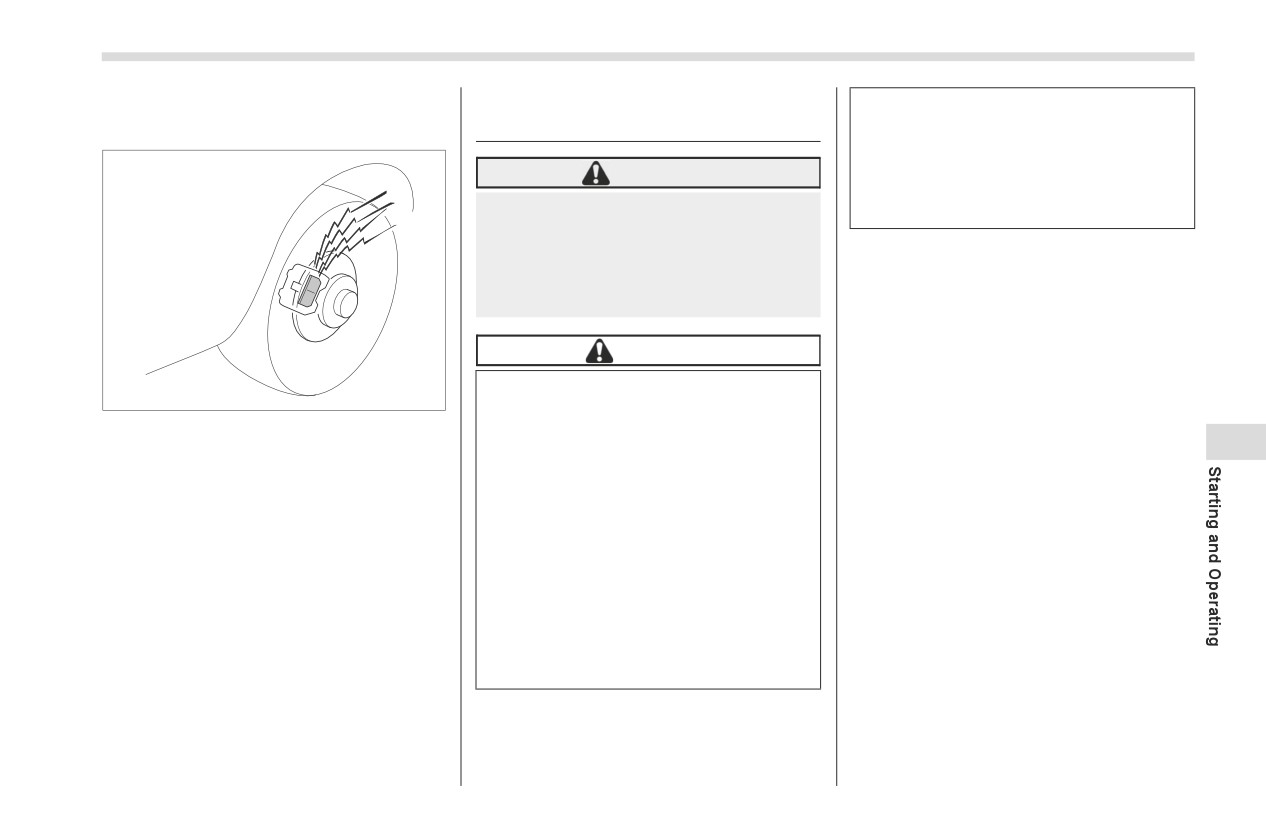
■ Disc Brake Pad Wear
7-11. ABS (Anti-Lock Brake
When you feel the ABS operating,
Warning Indicators
System)
you should maintain constant
brake pedal pressure. Do not
pump the brake pedal since doing
WARNING
so may defeat the operation of the
ABS.
Always use the utmost care in driv-
ing - overconfidence because you
are driving with an ABS equipped
The ABS prevents the lock-up of wheels
vehicle could easily lead to a seri-
which may occur during sudden braking or
ous accident.
braking on slippery road surfaces. This
helps prevent the loss of steering control
and directional stability caused by wheel
CAUTION
lock-up.
The ABS does not always
When the ABS is operating, you may hear
700040
decrease stopping distance. You
a chattering noise or feel a slight vibration
The disc brake pad wear warning indica-
should always maintain a safe
in the brake pedal. This is normal when
tors on the disc brakes give a warning
following distance from other
7
the ABS operates.
noise when the brake pads are worn.
vehicles.
If a squeaking or scraping noise is heard
When driving on badly surfaced
■ ABS Self-Check
from the disc brakes while braking, imme-
roads, gravel roads, icy road, or
You may feel a slight shock in the brake
diately have your vehicle inspected by the
over newly fallen snow, stopping
pedal and hear the operating noise of the
nearest SUBARU dealer.
distances may be longer for a
ABS from the engine compartment just
vehicle with the ABS than one
after the vehicle is started. This is caused
without. When driving under
by an automatic functional test of the ABS
these conditions, therefore,
being carried out and does not indicate
reduce your speed and leave
any abnormal condition.
ample distance from other vehi-
cles.
■ ABS Warning Light
Refer to "ABS Warning Light" ) P140.
246
Electronic Brake Force Distribution (EBD) System
7-12. Electronic Brake Force
■ EBD System Malfunctions
WARNING
Distribution (EBD) System
Driving with the brake system
The EBD system maximizes the effective-
warning light on is dangerous.
ness of the brakes by allowing the rear
This indicates your brake system
brakes to supply a greater proportion of
may not be working properly. If
the braking force. It functions by adjusting
the light remains on, have the
the distribution of braking force to the rear
brakes inspected by a SUBARU
wheels in accordance with the vehicle’s
dealer immediately.
loading condition and speed.
If at all in doubt about whether the
brakes are operating properly, do
The EBD system is an integral part of the
not drive the vehicle. Have your
ABS and uses some of the ABS compo-
nents to perform its function of optimizing
vehicle towed to the nearest
702779
SUBARU dealer for repair.
the distribution of braking force. If any of
the ABS components used by the EBD
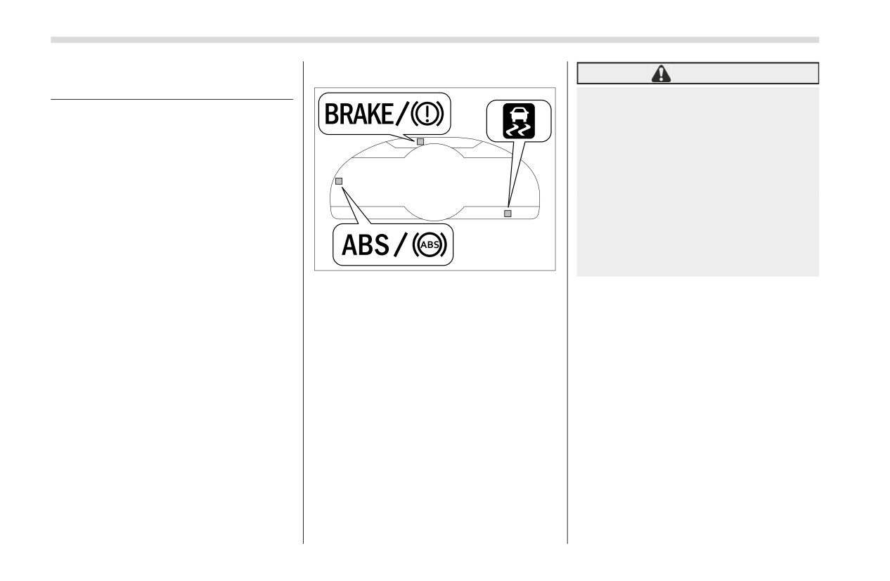
If a malfunction occurs in the EBD system,
function fails, the EBD system also stops
the system stops working and the
working.
following warning lights illuminate simulta-
When the EBD system is operating, you
neously.
may hear a chattering noise or feel a slight
Brake system warning light
vibration in the brake pedal. This is normal
ABS warning light
and does not indicate a malfunction.
Vehicle Stability Control
(VSC)
warning light
If all the warning lights remain on even
though the parking brake is released, the
brake fluid level may be low or there could
be a problem with the EBD system. Park
the vehicle in a safe place immediately
and contact an SUBARU dealer.
Vehicle Stability Control (VSC)/TRAC System
247
7-13. Vehicle Stability
Activation of the Vehicle Stability
WARNING
Control (VSC) system will cause opera-
Control (VSC)/TRAC System
tion of the steering wheel to feel
Directional control and power
slightly different compared to that for
may not be achievable while
■ Vehicle Stability Control
normal conditions.
driving on slippery road surfaces,
(VSC) System
It is always important to reduce
even if the TRAC system is oper-
In the event of wheelspin and/or skidding
speed when approaching a corner,
ating. Do not drive the vehicle in
on a slippery road surface and/or during
even if the vehicle is equipped with
conditions where stability and
cornering and/or an evasive maneuver,
Vehicle Stability Control (VSC) system.
power may be lost.
the Vehicle Stability Control (VSC) system
Always turn off the engine before
Always use the utmost care in
adjusts the engine’s output and the
replacing a tire as failure to do so may
driving
-
overconfidence
wheels’ respective braking forces to help
render the Vehicle Stability Control
because you are driving with a
maintain traction and directional control.
(VSC) system unable to operate
Vehicle Stability Control
(VSC)
The skid suppression function is designed
correctly.
system and TRAC system
to help maintain directional stability by
equipped vehicle could easily
suppressing the wheels’ tendency to slide
■ TRAC System
lead to a serious accident.
sideways during steering operations. Acti-
The TRAC system is designed to prevent
vation of this function is indicated by
7
spinning of the driving wheels on slippery
flashing of the Vehicle Stability Control
CAUTION
road surfaces, thereby helping to maintain
(VSC) operation indicator light.
traction and directional control. Activation
Even if your vehicle is equipped
of this function is indicated by flashing of
with Vehicle Stability Control
NOTE
the Vehicle Stability Control (VSC) opera-
(VSC) system and TRAC system,
In the following circumstances, the
tion indicator light. The TRAC system is
winter tires should be used when
vehicle may be less stable than it feels
also equipped with the brake LSD func-
driving on snow-covered or icy
to the driver. The Vehicle Stability
tion.
roads; in addition, vehicle speed
Control (VSC) system may therefore
should be reduced considerably.
operate. Such operation does not indi-
Simply having a Vehicle Stability
cate a system malfunction.
Control (VSC) system and TRAC
-
On gravel-covered or rutted
system does not guarantee that
roads
the vehicle will be able to avoid
-
On unfinished roads
accidents in any situation.
-
When the vehicle is fitted with
snow tires or winter tires
- CONTINUED -
248
Vehicle Stability Control (VSC)/TRAC System
The vehicle or steering wheel
Activation of the Vehicle Stability
-
All four wheels should be
shakes to a small degree.
Control (VSC) system and TRAC
fitted with tires of the same
An operating noise from the engine
system is an indication that the
size, type, and brand. Further-
compartment is heard briefly when
road being travelled on has a slip-
more, the amount of wear
starting the engine and when driving
pery surface;
since having
should be the same for all four
off after starting the engine.
Vehicle Stability Control
(VSC)
tires.
The brake pedal seems to jolt when
and TRAC is no guarantee that
-
Keep the tire pressure at the
driving off after starting the engine.
full vehicle control will be main-
proper level as shown on the
tained at all times and under all
label attached to the driver’s
conditions, its activation should
■ Vehicle Stability Control
side center pillar.
be seen as a sign that the speed
(VSC) System Monitor
-
When replacing a flat tire, use
of the vehicle should be reduced
only the specified temporary
Refer to "Vehicle Stability Control (VSC)
considerably.
spare tire. However, even with
Warning Light/Vehicle Stability Control
Whenever suspension compo-
the specified temporary spare
(VSC) Operation Indicator Light" ) P142
nents, steering components, or
tire, the effectiveness of the
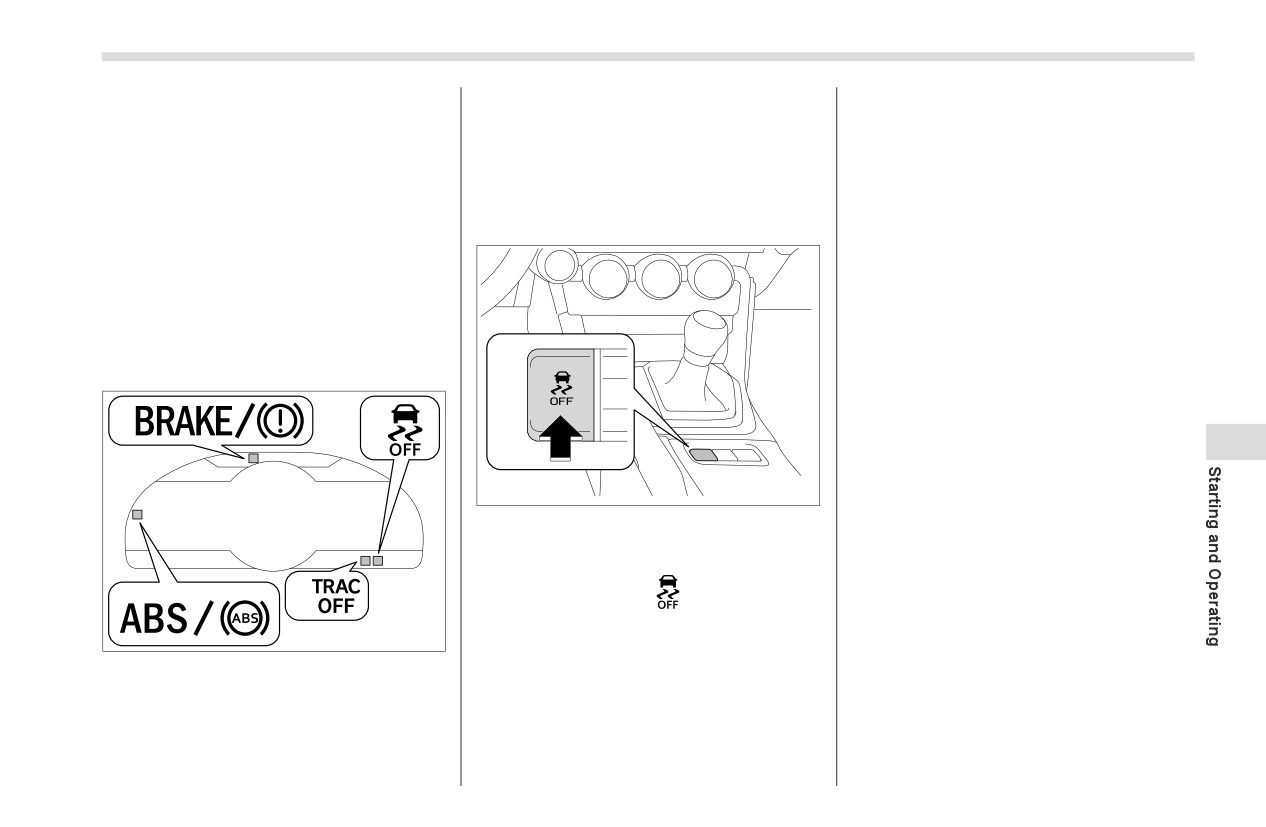
and "Vehicle Stability Control (VSC) OFF
an axle are removed from a
Vehicle Stability Control (VSC)
Indicator Light" ) P143.
vehicle equipped with the Vehicle
system and TRAC system will
Stability Control
(VSC) system
be reduced.
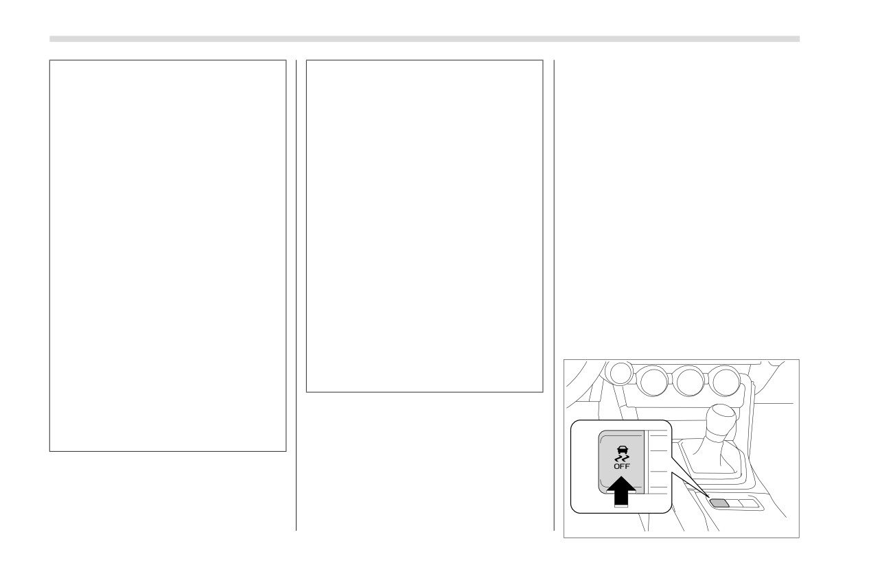
■ Vehicle Stability Control
and TRAC system, have an
If
non-matching tires are used,
(VSC) OFF Switch
inspection of that system
the Vehicle Stability Control
performed by an authorized
(VSC) system and TRAC system
SUBARU dealer.
may not operate correctly.
The following precautions should
be observed in order to ensure
that the Vehicle Stability Control
NOTE
(VSC) system and TRAC system
The Vehicle Stability Control
(VSC)
is operating properly.
system and TRAC system may be con-
sidered normal when the following
conditions occur.
Slight twitching of the brake pedal is
felt.
702785
Vehicle Stability Control (VSC)/TRAC System
249
▼ Disabling the TRAC System
Stability Control (VSC) system and TRAC
system except under above-mentioned
If the vehicle gets stuck in mud, dirt or
situations.
snow, the TRAC system may reduce
power from the engine to the wheels.
NOTE
Pressing the Vehicle Stability Control
When the switch has been pressed
(VSC) OFF switch to turn the system off
to deactivate the Vehicle Stability
may make it easier for you to rock the
Control
(VSC) system and TRAC
vehicle in order to free it. In this case, the
system, the Vehicle Stability Control
brake LSD function remains on. To turn
(VSC) system and TRAC system auto-
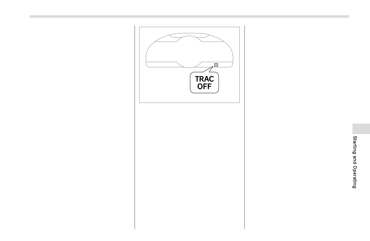
the TRAC system off, quickly press and
matically reactivates itself the next
release the button. The TRAC OFF indi-
time the ignition switch is turned to the
cator light will come on. Press the button
702831
“OFF” position and the engine is
again to turn the system back on.
restarted.
Creating adequate driving wheel slip by
▼ Turning Off both Vehicle Stability
If the switch is held down for 30
deactivating the TRAC system may help
Control (VSC) and TRAC Systems
seconds or longer, the indicator light
to recover from the loss of traction. Use
To turn the Vehicle Stability Control (VSC)
turns off, the Vehicle Stability Control
the Vehicle Stability Control (VSC) OFF
(VSC) system is activated, and the
7
systems and TRAC system off, press and
switch as necessary.
hold the Vehicle Stability Control (VSC)
system ignores any further pressing of
A standing start on a steeply sloping
OFF switch for more than 3 seconds while
the switch. To make the switch usable
road with a snowy, gravel-covered, or
the vehicle is stopped. The TRAC OFF
again, turn the ignition switch to the
otherwise slippery surface
indicator light and the Vehicle Stability
“OFF” position and restart the engine.
Extrication of the vehicle when its
Control
(VSC) OFF indicator light will
When the switch is pressed to deac-
wheels are stuck in mud or deep snow
come on. However, on vehicles with an
tivate the Vehicle Stability Control
automatic transmission, the brake LSD
(VSC) system and TRAC system, the
function will remain on. Press the button
vehicle’s running performance is
again to turn the systems back on. With
comparable with that of a vehicle that
the Vehicle Stability Control (VSC) system
does not have a Vehicle Stability
and TRAC system deactivated, traction
Control
(VSC) system and TRAC
and stability enhancement offered by
system. Do not deactivate the Vehicle
Vehicle Stability Control
(VSC) system
Stability Control
(VSC) system and
and TRAC system is unavailable. There-
TRAC system except when absolutely
fore you should not deactivate the Vehicle
necessary.
- CONTINUED -
250
TRACK Mode
Even when the TRAC system is
7-14. TRACK Mode
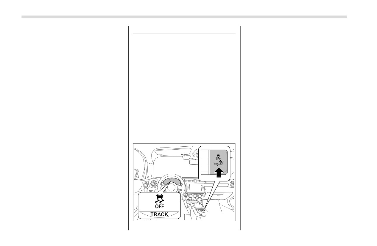
The TRACK indicator and Vehicle Stability
deactivated, components of the brake
Control
(VSC) OFF indicator come on
control system may still activate. When
when in TRACK mode.
■ TRACK Mode
the brake control system is activated,
To change back to normal mode while in
Your vehicle is equipped with two types of
the Vehicle Stability Control
(VSC)
TRACK mode, press Vehicle Stability
control modes to accommodate various
operation indicator light flashes.
Control (VSC) OFF switch or the TRACK
driving preferences. The control modes
switch.
can be selected with the TRACK switch.
Normal mode allows secure and smooth
normal driving. When the switch is
pressed and held for 1 second or more,
TRACK mode is activated. Control char-
acteristics such as the Vehicle Stability
Control (VSC) and TRAC are adjusted to
afford maneuverability closer to what a
driver may desire, while a sense of secu-
rity is retained.
▼ TRACK mode/Normal mode
702840
Tire Pressure Monitoring System (TPMS) (If Equipped)
251
■ Selecting TRAC Mode and Vehicle Stability Control (VSC) Mode
7-15. Tire Pressure Moni-
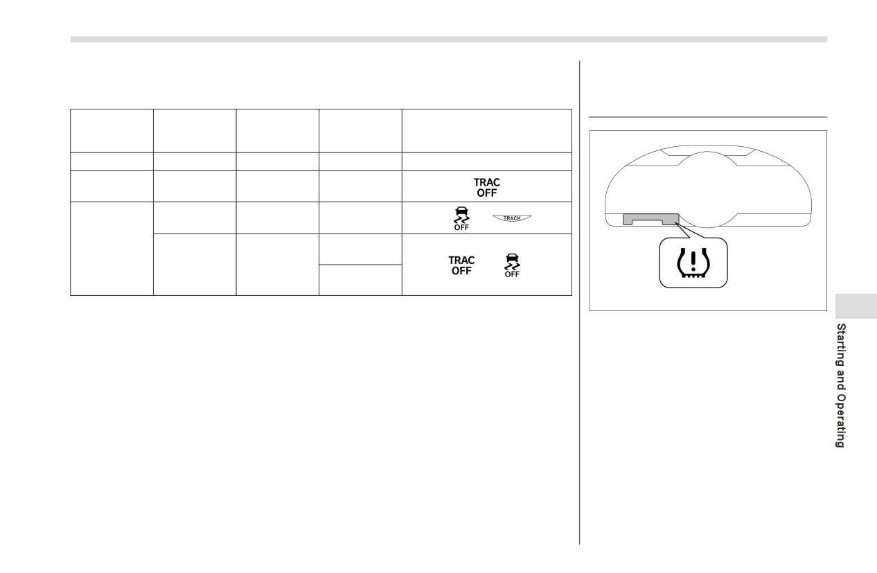
Modes can be selected to suit your driving conditions as follows:
toring System (TPMS) (If
Equipped)
Vehicle Sta-
Driving con-
Brake LSD
TRAC modes
bility Control
Indicator lights
ditions
function
(VSC) modes
Normal roads
Normal mode
Normal mode
Normal mode
ʊ
Rough roads
Off
Normal mode
Normal mode
TRACK mode
TRACK mode
TRACK mode
TRACK mode
Sport driving
(AT models)
Off
Off
Off (MT mod-
els)
702780
7
NOTE
Low tire pressure warning light
When the ignition switch is turned “OFF” position after driving in TRACK mode,
The tire pressure monitoring system
the mode is automatically deactivated.
provides the driver with a warning
message by sending a signal from a
sensor that is installed in each wheel
when tire pressure is severely low.
The tire pressure monitoring system will
activate only when the vehicle is driven at
speeds above 25 mph (40 km/h). Also,
this system may not react immediately to
a sudden drop in tire pressure
(for
example, a blow-out caused by running
over a sharp object).
- CONTINUED -
252
Tire Pressure Monitoring System (TPMS) (If Equipped)
Even when the vehicle is driven a
When a spare tire is mounted or a
WARNING
very short distance, the tires get
wheel rim is replaced without the
If the low tire pressure warning
warm and their pressures
original pressure sensor/trans-
light illuminates while driving,
increase accordingly. Be sure to
mitter being transferred, the low
never brake suddenly. Instead,
let the tires cool thoroughly
tire pressure warning light will
perform the following procedure.
before adjusting their pressures
illuminate steadily after blinking
Otherwise an accident involving
to the standard values shown on
for approximately one minute.
serious vehicle damage and
the tire inflation pressure label.
This indicates the TPMS is unable
serious personal injury could
Refer to "Tires and Wheels"
to monitor all four road wheels.
occur.
) P358. The tire pressure moni-
Contact your SUBARU dealer as
(1) Keep driving straight ahead
toring system does not function
soon as possible for
tire and
while gradually reducing
when the vehicle is stationary.
sensor replacement
and/or
speed.
After adjusting the tire pressures,
system resetting.
increase the vehicle speed to at
(2) Slowly pull off the road to a
least 25 mph (40 km/h) to start the
safe place.
TPMS rechecking of the tire infla-
tion pressures. If the tire pres-
(3) Check the pressure for all
sures are now above the severe
four tires and adjust the pres-
low pressure threshold, the low
sure to the COLD tire pres-
tire pressure warning light should
sure shown on the tire
turn off a few minutes later.
inflation pressure label on the
center pillar on the driver’s
If this light still illuminates while
side.
driving after adjusting the tire
pressure, a tire may have signifi-
cant damage and a fast leak that
causes the tire to lose air rapidly.
For details, refer to "Flat Tires"
) P303.
Tire Pressure Monitoring System (TPMS) (If Equipped)
253
When a tire is repaired with liquid
■ Certification for the Trans-
CAUTION
sealant, the tire pressure warning
mitter
valve and transmitter may not
Do not place metal film or any metal
U.S.-spec. models
operate properly. If a liquid
parts under the driver’s seat. This
FCC ID: PAXPMVE000
sealant is used, contact your
may cause poor reception of the
nearest SUBARU dealer or other
signals from the tire pressure sen-
NOTE
qualified service shop as soon as
sors, and the tire pressure monitor-
possible. Make sure to replace
ing system will not function
This device complies with part 15 of
the tire pressure warning valve
properly.
the FCC Rules. Operation is subject to
and transmitter when replacing
the following two conditions: (1) This
the tire. You may reuse the wheel
device may not cause harmful interfer-
■ Certification for the Receiver
if there is no damage to it and if
ence, and (2) this device must accept
the sealant residue is properly
FCC ID: HYQ23ABG
any interference received, including
cleaned off. Do not inject any tire
interference that may cause unde-
liquid or aerosol tire sealant into
NOTE
sired operation.
the tires, as this may cause a
This device complies with part 15 of
FCC WARNING
malfunction of the tire pressure
the FCC Rules. Operation is subject to
Changes or modifications not
7
sensors. If the light illuminates
the following two conditions: (1) This
expressly approved by the party
steadily after blinking for approx-
device may not cause harmful interfer-
responsible for compliance could void
imately one minute, promptly
ence, and (2) this device must accept
the user’s authority to operate the
contact a SUBARU dealer to have
any interference received, including
equipment.
the system inspected.
interference that may cause unde-
Mexico-spec. models
sired operation.
MEX: RLVPAPM17-1337
FCC WARNING
Changes or modifications not
expressly approved by the party
responsible for compliance could void
the user’s authority to operate the
equipment.
- CONTINUED -
254
Tire Pressure Monitoring System (TPMS) (If Equipped)
■ TPMS Screen
■ How to Initialize the Tire
4. Press and hold the TPMS set switch
until the low tire pressure warning light
Pressure Monitoring System
blinks slowly 3 times.
(If Equipped)
■ If You Press the Tire Pres-
1. Park the vehicle in a safe place and
turn the ignition switch to the “OFF” posi-
sure Monitoring Reset
tion.
Switch Accidentally
Initialization cannot be performed while
If initialization is performed, adjust the tire
the vehicle is moving.
inflation pressure to the specified level
2. Adjust the tire inflation pressure to the
and initialize the tire pressure monitoring
specified cold tire inflation pressure level.
system again.
Refer to "Tires" ) P385.
Make sure to adjust the tire pressure to
■ Initialization Procedure
702781
the specified cold tire inflation pressure
Make sure to carry out initialization
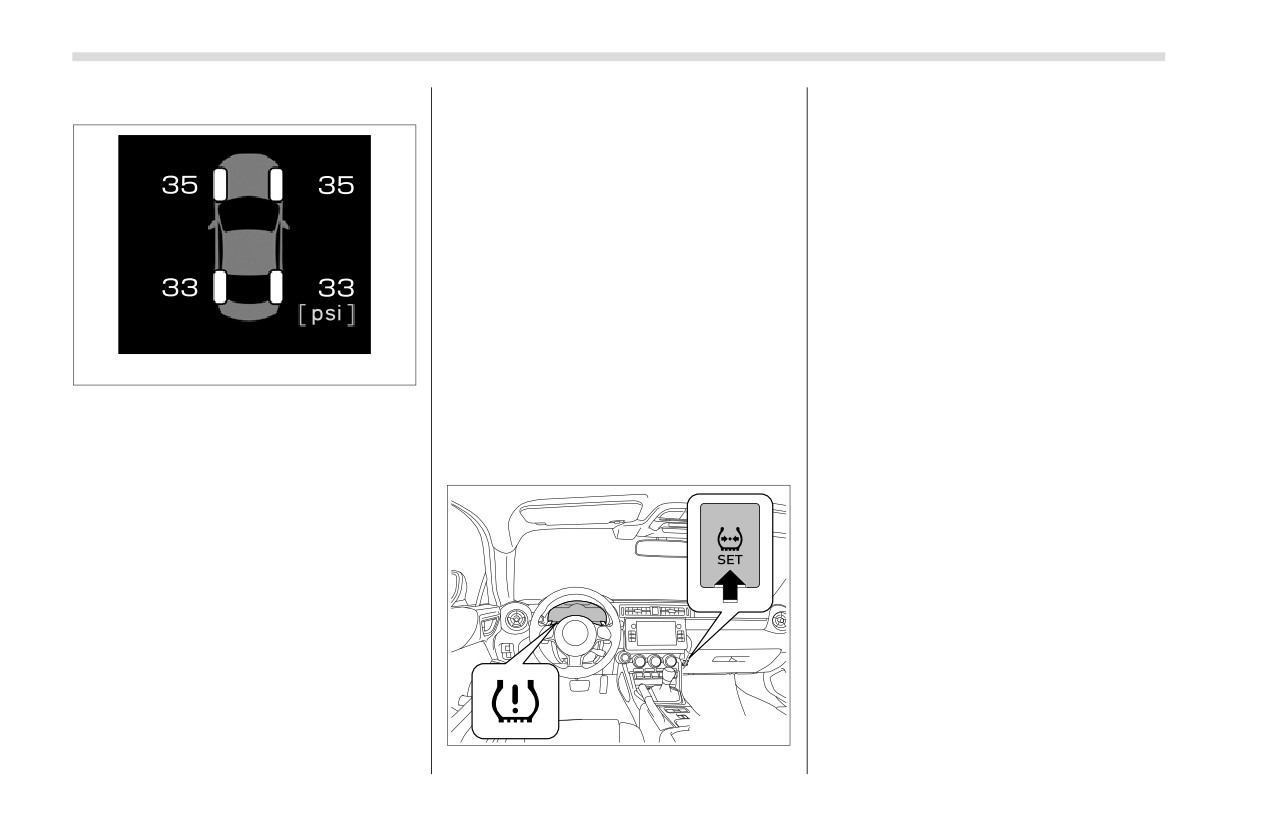
This screen displays each tire pressure.
level. The tire pressure monitoring system
after adjusting the tire inflation pressure.
Refer to "Drive Information" ) P153.
will operate based on this pressure level.
Also, make sure the tires are cold before
3. Turn the ignition switch to the “ON”
carrying out initialization or tire inflation
■ Initializing the Tire Pressure
position.
pressure adjustment.
Monitoring System
If you have accidentally turned the igni-
When setting the tire inflation pressure
tion switch to the “OFF” position during
above the specified level, initialize the tire
initialization, it is not necessary to press
pressure monitoring system.
the TPMS set switch again as initialization
When the tire pressure monitoring system
will restart automatically when the engine
is initialized, the current tire inflation pres-
is restarted.
sure is set as the standard pressure.
If you accidentally press the TPMS set
switch when initialization is not necessary,
adjust the tire inflation pressure to the
specified level when the tires are cold, and
conduct initialization again.
702838
Parking Your Vehicle
255
■ When Initialization of the Tire
■ Registering ID Codes
7-16. Parking Your Vehicle
Pressure Monitoring System
Every tire pressure warning valve and
has Failed
transmitter has a unique ID code. In addi-
WARNING
tion to the set of tire pressure monitoring
Initialization can be completed in a few
Never leave unattended children
system sensor ID codes initially registered
minutes. However, in the following case,
or pets in the vehicle. They could
to the vehicle, a second set of ID codes
the settings have not been recorded and
accidentally injure themselves or
can be registered.
the system will not operate properly. If
others through inadvertent oper-
A second set of tire pressure monitoring
repeated attempts to record tire inflation
ation of the vehicle. Also, on hot
system sensor ID codes can be registered
pressure settings are unsuccessful, have
or sunny days, the temperature in
at your SUBARU dealer. When 2 sets of
the vehicle checked at your SUBARU
a closed vehicle could quickly
ID codes have been registered, either ID
dealer.
become high enough to cause
code set can be selected.
When operating the TPMS set switch,
severe or possibly fatal injuries to
low tire pressure warning light does not
people.
■ Changing the ID code set
blink 3 times.
Do not park the vehicle over flam-
After carrying out the initialization
1. Park the vehicle in a safe place and
mable materials such as dry
procedure, the low tire pressure warning
turn the ignition switch to the “ON” posi-
grass, waste paper or rags, as
light blinks for 1 minute then stays on after
tion.
7
they may burn easily if they come
driving for 20 minutes.
2. Press the TPMS set switch 3 times
near hot engine or exhaust
within 3 seconds.
system parts.
WARNING
3. The low tire pressure warning light will
Be sure to stop the engine if you
illuminate for 3 seconds and then blink 3
take a nap in the vehicle. If engine
Do not operate the TPMS set switch
times.
exhaust gas enters the passenger
without first adjusting the tire infla-
compartment, occupants in the
4. The low tire pressure warning light will
tion pressure to the specified level.
vehicle could die from carbon
blink for 1 minute and then illuminate.
Otherwise, the low tire pressure
monoxide (CO) contained in the
5. When the ID code change has
warning light may not come on even
exhaust gas.
completed, the tire pressure monitoring
if the tire inflation pressure is low,
light will turn off.
or it may come on when the tire
inflation pressure is actually nor-
Check that tire pressures are displayed on
■ Parking Brake
mal.
the TPMS screen.
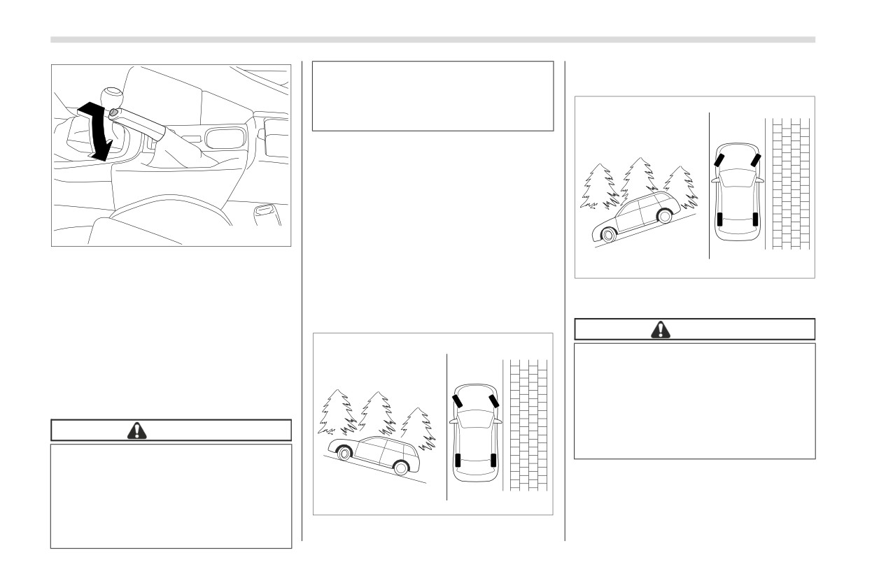
To set the parking brake, depress the
brake pedal firmly and hold it down until
the parking brake lever is fully pulled up.
- CONTINUED -
256
Parking Your Vehicle
headed up the hill, the front wheels should
The braking power of the parking
be turned away from the curb.
brake may not be sufficient when
stronger braking power is
needed.
■ Parking Tips
When parking your vehicle, always
perform the following items.
Apply the parking brake firmly.
For MT models, put the shift lever in the
702782
“1” (1st) for upgrade or “R” (Reverse) for a
To release the parking brake, pull the
downgrade.
700898
lever up slightly, press the release button,
For AT models, put the select lever in
then lower the lever while keeping the
the “P” (Park) position.
When facing downhill, the front wheels
button pressed.
Never rely on the mechanical friction of
should be turned into the curb.
When the parking brake is set while the
the transmission alone to hold the vehicle.
engine is running, the parking brake
CAUTION
warning light illuminates. After starting the
If your vehicle has a front under-
vehicle, be sure that the warning light has
spoiler and rear underspoiler (both
turned off before the vehicle is driven.
optional), pay attention to blocks
Refer to "Brake System Warning Light"
and other obstructions on the
) P140.
ground when parking. The under-
spoilers could be damaged by con-
CAUTION
tact with them.
Never drive while the parking
brake is set because this will
cause unnecessary wear on the
brake linings. Before starting to
700897
drive, always make sure that the
parking brake has been fully
When parking on a hill, always turn the
released.
steering wheel. When the vehicle is
Hill Start Assist System
257
7-17. Hill Start Assist System
In both these cases, the Hill start assist
1
system operates under the following
conditions.
WARNING
The clutch pedal is depressed while the
The Hill start assist system is a
brake pedal is also depressed
(MT
device only for helping the driver
models).
to START the vehicle on an uphill
The vehicle has stopped with the brake
grade. To prevent accidents when
pedal depressed (AT models).
the vehicle is parked on a slope,
Braking power is maintained temporarily
be sure to firmly set the parking
(for approximately 2 seconds) by the Hill
brake. When setting the parking
A
B
start assist system after the brake pedal is
brake, make sure that the vehicle
released. The driver is therefore able to
remains stationary when the
start the vehicle in the same way as on a
clutch pedal
(MT models) and
level grade, just using the clutch pedal
brake pedal
(both MT and AT
2
(MT models only) and accelerator pedal
models) are released.
(all models).
Do not turn the ignition switch to
If the braking power of the Hill start assist
7
the “OFF” position while the Hill
system is insufficient after the brake pedal
start assist system is operating.
is released, apply more braking power by
The Hill start assist system will be
depressing the brake pedal again.
deactivated and may lead to an
accident.
The Hill start assist system may not
operate on slight grades. Also, the Hill
start assist system does not operate in the
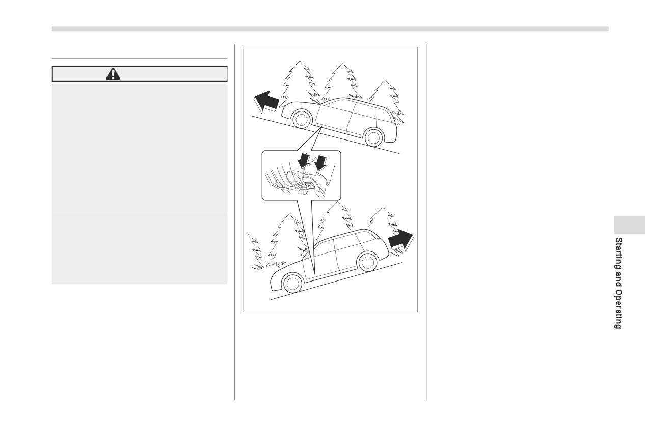
The Hill start assist system is a device to
701116
following cases.
make the following vehicle operations
easier.
1)
Starting forward facing uphill
2)
Starting backward facing downhill
A)
Brake pedal (both MT models and AT
models)
B)
Clutch pedal (MT models only)
- CONTINUED -
258
Hill Start Assist System
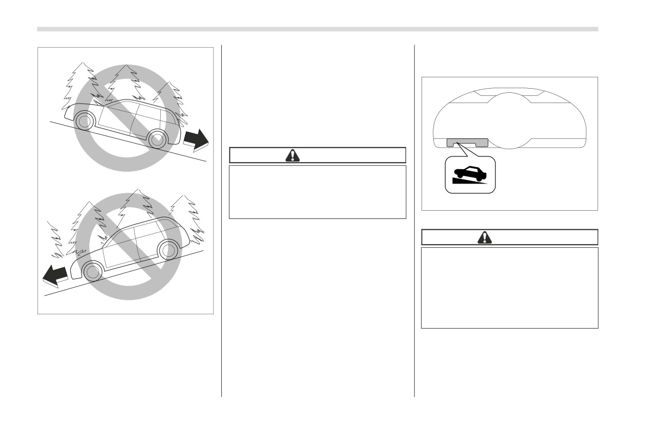
While the Hill start assist indicator light
■ To Activate/Deactivate the
is illuminated. Refer to "Hill Start Assist
Hill Start Assist System
Indicator Light" ) P150.
When using the Hill start assist system, a
braking effect may be felt even after the
brake pedal has been released. However,
for MT models, this braking effect should
disappear once the clutch pedal is
released.
CAUTION
The braking power of the Hill start
assist system may not be sufficient
when strong braking power is
702783
needed.
Hill start assist indicator light
NOTE
CAUTION
A slight jolt may be felt when the vehi-
cle begins to move forward after being
When starting on an uphill grade,
reversed.
make sure the Hill start assist indi-
cator light is on.
If the Hill start assist indicator light
701109
is off, make sure the parking brake
is applied.
When starting backward facing uphill
When starting forward facing downhill
To activate or deactivate the Hill start
While the parking brake is applied
assist system, perform the following
While the ignition switch is in the “ACC”
steps.
or “OFF” position
Hill Start Assist System
259
NOTE
4.
Confirm the following items.
8. Turn the ignition switch to the “OFF”
(1) The ABS warning light turns off.
position. Hill start assist is deactivated.
If you make an error when performing
any steps in the following procedure,
(2) The brake system warning light
place the ignition switch in the “OFF”
illuminates.
NOTE
position once and then start over
(3) The Vehicle Stability Control
When the Hill start assist system is
again.
(VSC) OFF indicator light turns off.
deactivated, the Hill start assist indica-
(4) TRAC OFF indicator light turns off.
tor light turns off.
▼ To deactivate
▼ To reactivate
1. Park your vehicle in a flat and safe
To reactivate Hill start assist system,
location and apply the parking brake.
repeat steps 1 to 8. When the Hill start
2. Turn the ignition switch to the “OFF”
assist system is activated, the Hill start
position.
assist indicator light illuminates.
3. Restart the engine.
■ Hill Start Assist Indicator
2
3
Light
Refer to "Hill Start Assist Indicator Light"
7
) P150.
702785
5.
Press and hold the Vehicle Stability
Control (VSC) OFF switch for 30 seconds
until the Vehicle Stability Control (VSC)
4
1
OFF indicator light
on the combi-
nation meter turns on and off.
702784
6. Within 5 seconds, release the Vehicle
Stability Control (VSC) OFF switch.
7. Within
2 seconds, press back the
Vehicle Stability Control
(VSC) OFF
switch.
The Hill start assist indicator light turns on
and off.
- CONTINUED -
260
Cruise Control (Models without the EyeSight system)
7-18. Cruise Control (Models
When using the cruise control,
“ON-OFF” switch
always set the speed appropri-
without the EyeSight system)
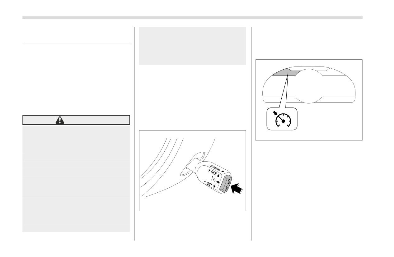
1. After the engine has started, press the
ately according to the speed limit,
“ON-OFF” switch of the cruise control
traffic flow, road conditions, and
switch.
NOTE
other conditions.
For models with the EyeSight system:
Refer to the Owner’s Manual supple-
ment for the EyeSight system.
NOTE
Cruise control enables you to maintain a
Make sure the cruise control system is
constant vehicle speed without holding
turned off when the cruise control is
your foot on the accelerator pedal and it is
not in use to avoid unintentionally set-
operative when the vehicle speed is 20
ting of the cruise control.
mph (30 km/h) or more.
WARNING
■ To Set Cruise Control
Do not use the cruise control
702792
under any of the following condi-
tions. These may cause loss of
Cruise control indicator light
vehicle control.
The cruise control indicator light (white) on
-
In heavy traffic
the combination meter will illuminate.
-
On roads with sharp bends
2. Depress the accelerator pedal until the
vehicle reaches the desired speed.
-
On winding roads
-
On slippery roads, such as
those covered with rain, ice or
snow
-
On steep hills
702791
Vehicle speed may exceed the
set speed when driving down
a steep hill.
-
During emergency towing
Cruise Control (Models without the EyeSight system)
261
vehicle. When the accelerator pedal is
released, the vehicle will return to and
maintain the previous cruising speed.
■ To Temporarily Cancel the
Cruise Control
The cruise control can be temporarily
canceled in the following ways.
1
2
702793
702876
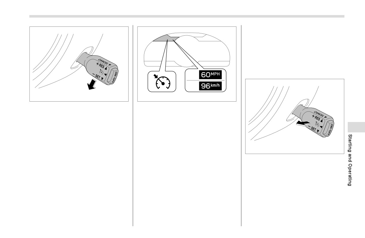
3. Push the Cruise control switch to the “-
Cruise control indicator light
SET” side and release it.
1) When setting the displayed unit as
“MPH”
NOTE
2) When setting the displayed unit as
“km/h”
7
When setting a cruise speed for the
first time during a drive, both “-SET”
At this time, the cruise control indicator
and “+RES” may be used to set the ini-
light (green) is illuminated in the combina-
tial cruise speed.
702795
tion meter. The set speed will be shown on
the combination meter. You can change
Pulling the cruise control switch.
the displayed units by operating the
Depress the brake pedal.
combination meter display. For details,
refer to "Combination Meter Settings"
Depress the clutch pedal.
) P130.
When the cruise control is cancelled, the
The vehicle will maintain the desired
cruise control indicator light in the combi-
nation meter will change from green to
speed.
white.
Vehicle speed can be temporarily
increased while driving with the cruise
control activated. Simply depress the
accelerator pedal to accelerate the
- CONTINUED -
262
Cruise Control (Models without the EyeSight system)
■ To Change the Cruising
(0.6 mph) each time by pushing the cruise
control switch to the “+RES” side.
Speed
▼ To increase the speed (by the
▼ To increase the speed (by acceler-
cruise control switch)
ator pedal)
1. Depress the accelerator pedal to
accelerate the vehicle to the desired
speed.
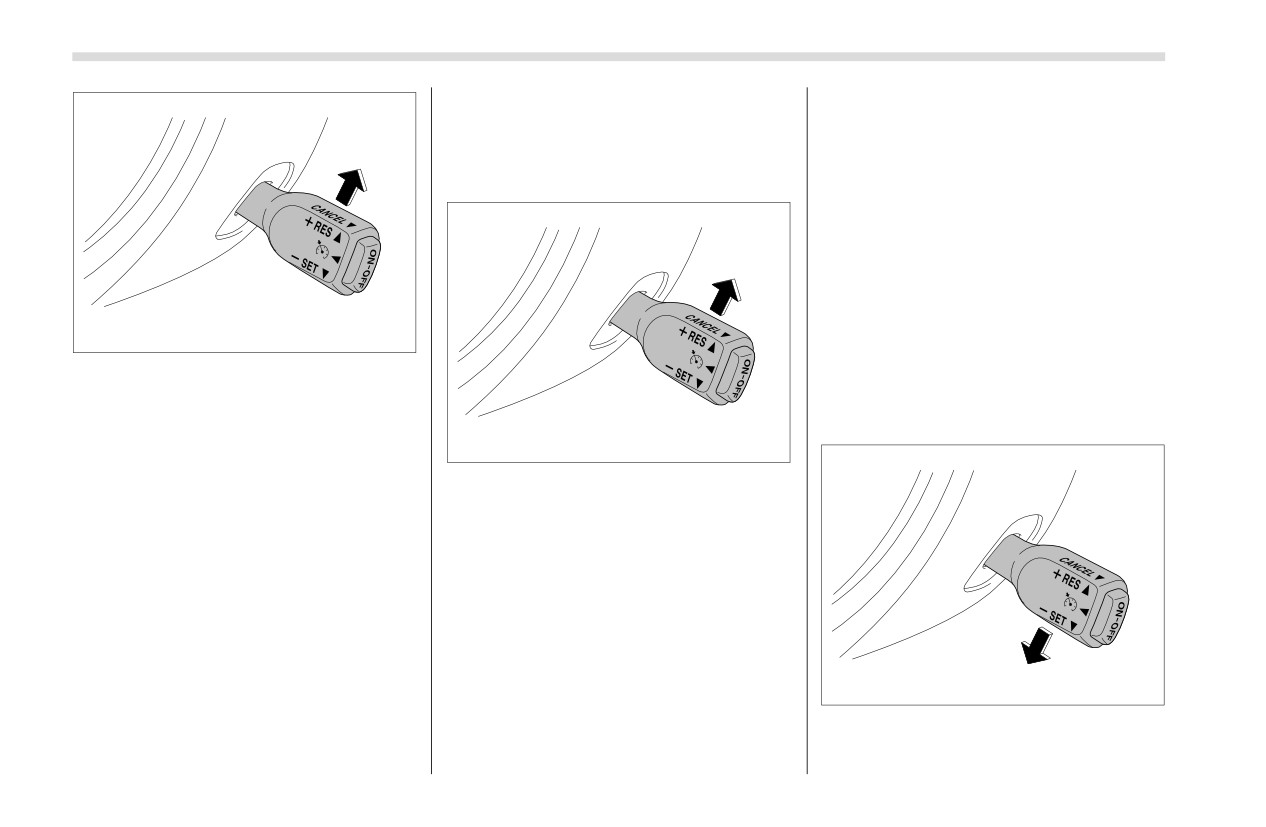
2. Push the cruise control switch to the “-
SET” side once. Now the desired speed is
set and the vehicle will keep running at
702796
that speed without depressing the accel-
erator pedal.
To resume the cruise control after it has
been temporarily canceled and with
▼ To decrease the speed (by the
vehicle speed of approximately 20 mph
cruise control switch)
(30 km/h) or more, push the lever up to
return to the original cruising speed auto-
702796
matically.
Push the cruise control switch
to the
At this time, the cruise control indicator
“+RES” side and hold it until the vehicle
light in the combination meter will change
reaches the desired speed. Then, release
from white to green.
the switch. The vehicle speed at that
moment will be memorized and treated as
■ To Turn Off the Cruise
the new set speed.
Control
When setting the displayed unit as
“MPH”:
There are two ways to turn off the cruise
control:
The set speed can be increased 1 mph
(1.6 km/h) each time by pushing the cruise
Press the
“ON-OFF” switch of the
control switch to the “+RES” side.
702793
cruise control switch again.
When setting the displayed unit as
Turn the ignition switch to the “ACC” or
Push the cruise control switch to the “-
“km/h”:
“OFF” position (but only when the vehicle
SET” side and hold it until the vehicle
The set speed can be increased 1 km/h
is completely stopped).
reaches the desired speed. Then, release
Rear View Camera
263
the switch. The vehicle speed at that
7-19. Rear View Camera
Since the range of the image on
moment will be memorized and treated as
the monitor is limited, always
the new set speed.
check the rear view and the
When setting the displayed unit as
surrounding area with your eyes
“MPH”:
and mirrors, and move backward
The set speed can be decreased 1 mph
at a slow speed. Moving back-
(1.6 km/h) each time by pushing the cruise
ward only by checking the rear
control switch to the “-SET” side.
view image from the camera
When setting the displayed unit as
could cause an accident.
“km/h”:
Do not disassemble or modify the
The set speed can be decreased 1 km/h
camera, switch or wiring. If
(0.6 mph) each time by pushing the cruise
smoke comes out or you smell a
control switch to the “-SET” side.
strange odor, stop using the rear
702799
view
camera
immediately.
▼ To decrease the speed (by brake
Contact your SUBARU dealer for
pedal)
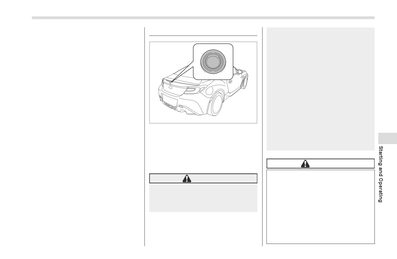
A rear view camera is attached to the
an inspection. Continued use
trunk lid. When the ignition switch is in the
may result in accident, fire or
1. Depress the brake pedal to release
“ON” position and the shift lever
(MT
7
electric shock.
cruise control temporarily.
models) or select lever (AT models) is set
2. When the speed decreases to the
to “R”, the rear view camera automatically
desired speed, push the cruise control
displays the rear view image behind the
CAUTION
switch to the “-SET” side once. Now the
vehicle on the center information display.
desired speed is set and the vehicle will
When washing your vehicle with
keep running at that speed without
WARNING
a high-pressure washer, do not
depressing the accelerator pedal.
allow water to touch the camera
Since the rear view camera uses a
directly. Entry of water in the
wide-angle lens, the image on the
■ Cruise Control Indicator
camera lens may result in
monitor is different from the
Light
condensation, malfunction, fire
actual view in terms of distance.
or electric shock.
Refer to "Combination Meter Settings"
) P130.
Since the camera is a precision
device, do not subject it to strong
impacts. Otherwise, malfunction,
fire or electric shock may occur.
- CONTINUED -

264
Rear View Camera
When waxing the vehicle, be careful
vehicle. When the lever is set to other
If mud or snow sticks to or is
not to apply the wax to the camera. If it
positions, the image before setting to “R”
frozen on the camera, you must
comes in contact with the camera,
is displayed.
be very careful when removing it.
moisten a clean cloth with a diluted
Otherwise, damage to the camera
1. Set the ignition switch to “ON”.
neutral detergent to remove the wax.
may cause a fire or electric shock.
The camera lens has a hard coating
2. Set the shift lever/select lever to “R”.
Pour water or lukewarm water
to help prevent scratches. However,
over the camera to remove mud
when washing the vehicle or cleaning
NOTE
and ice, and wipe it with a soft,
the camera lens, be careful not to
The image of the rear view camera is
dry cloth.
scratch the camera lens. Do not use a
horizontally reversed as is the case
Do not put a flame close to the
washing brush directly on the camera
with the vehicle inside mirror or the
camera or wiring. Otherwise,
lens. The image quality of the rear view
outside mirror.
damage or fire may occur.
camera may deteriorate.
When “Rear Camera Delay Control”
When replacing the fuse, be sure
Strong light shined on the camera
is on, the rear view image from the rear
to use a fuse with the specified
lens may develop vertical lines around
view camera will be displayed on the
rating. Use of a fuse with a
the light source. This is not a malfunc-
center information display for a certain
different rating may result in a
tion.
amount of time after the shift lever (MT
malfunction.
Under the fluorescent light, the
models) or select lever (AT models) is
If you use the rear view camera
display may flicker. However, this is
shifted from “R” to another position.
for a long time while the engine is
not a malfunction.
When any of the following conditions
not operated, the battery may
The image of the rear view camera
are met, the rear view image will be
become completely discharged.
may be slightly different from the
canceled:
actual color of the objects.
-
The select lever is shifted to “P”
If there is a malfunction on the
(AT models)
NOTE
center information display, refer to
-
The vehicle speed becomes
Do not wipe the camera with
"Malfunctions of the Center Informa-
approximately 5 mph (8 km/h) or
alcohol, benzine or paint thinner.
tion Display" ) P327.
more
Otherwise, discoloration may occur.
-
The parking brake is engaged
To remove contamination, wipe the
■ How to Use the Rear View
-
9 seconds have elapsed since
camera with a cloth moistened with a
the shift lever (MT models) or select
Camera
diluted neutral detergent. Then wipe it
lever (AT models) was shifted from
with a soft, dry cloth.
When the shift lever/select lever is set to
“R” to another position
“R”, the rear view camera automatically
displays the rear view image from the
Rear View Camera
265
To turn the function on and off, refer to
"General settings" ) P161.
It may be difficult to see the image of
the rear view camera in the following
cases. This is not a malfunction of the
camera.
-
The vehicle is in a dark place (at
night, in a tunnel, etc.).
-
The vehicle is in an extremely hot
or cold place.
-
An object (such as raindrops,
snow, dirt, etc.) that disturbs the
601498
601103
view of the rear view camera sticks
to the lens of the camera.
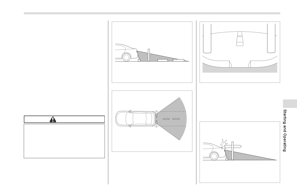
Range of view
Image from camera
-
Strong light is shining directly on
The area from the rear end of the bumper
the camera lens (occasionally, there
can be viewed. Areas at both ends of the
are vertical lines on the screen).
bumper and areas just under the bumper
cannot be viewed.
7
■ Viewing Range on the Screen
Also, the image from the rear view camera
looks shorter than the actual distance.
CAUTION
The range that can be viewed with
the rear view camera is limited.
Always be sure to check with your
eyes when moving backward and
proceed slowly. Otherwise, it may
601499
cause an accident or injury.
Range of view
601500
- CONTINUED -
266
Rear View Camera
Range of view
switch before shifting to the
“R”
CAUTION
range. Then, the warning message will
be displayed.
When moving backward, always
check the back with your eyes
without relying on the help lines.
7
Otherwise, it may cause an acci-
1
dent or injury.
2
3
The actual position may be
different from the indication of
4
the help lines.
5
Differences may occur due to the
6
number of passengers or the
601105
loaded cargo.
Check Surroundings Before Backing Up
When the vehicle is on a slope or
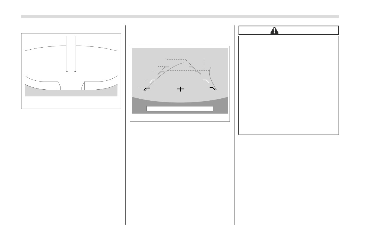
Image from camera
702392
inclined against the road, the
The area above the camera cannot be
indication is different from the
viewed. If there is an object that has a
Help lines
actual position.
wide projection on its upper part such as a
1) Vehicle width line (oblique vertical line)
sign pole behind the vehicle, the projec-
2) Approx. 10 ft (3 m) from the bumper
tion cannot be seen on the screen.
(green horizontal line)
NOTE
3) Approx. 6 ft (2 m) from the bumper
When “Steering Angle Lines” is off,
(green horizontal line)
■ Help Lines
the dynamic guidelines will be disap-
4) Approx. 3 ft (1 m) from the bumper
pear on the center information display.
The help lines are a guide to help you
(yellow horizontal line)
To turn the dynamic guidelines on and
realize the actual distance from the screen
5) Approx. 1.5 ft (0.5 m) from the bumper
off, refer to "General settings" ) P161.
image.
(red horizontal line)
6) Vehicle centerline
▼ Difference between screen image
NOTE
7) Dynamic guidelines
and actual road
If you shift to the “R” range within sev-
When the shift lever/select lever is set to
The distance markers show the distance
eral seconds after turning on the igni-
“R”, the monitor screen displays the help
for a level road when the vehicle is not
tion switch, the warning message may
lines together with the rear view image.
loaded. It may be different from the actual
not be displayed. Wait for several sec-
distance depending on the loading condi-
onds after turning on the ignition
tions or road conditions.
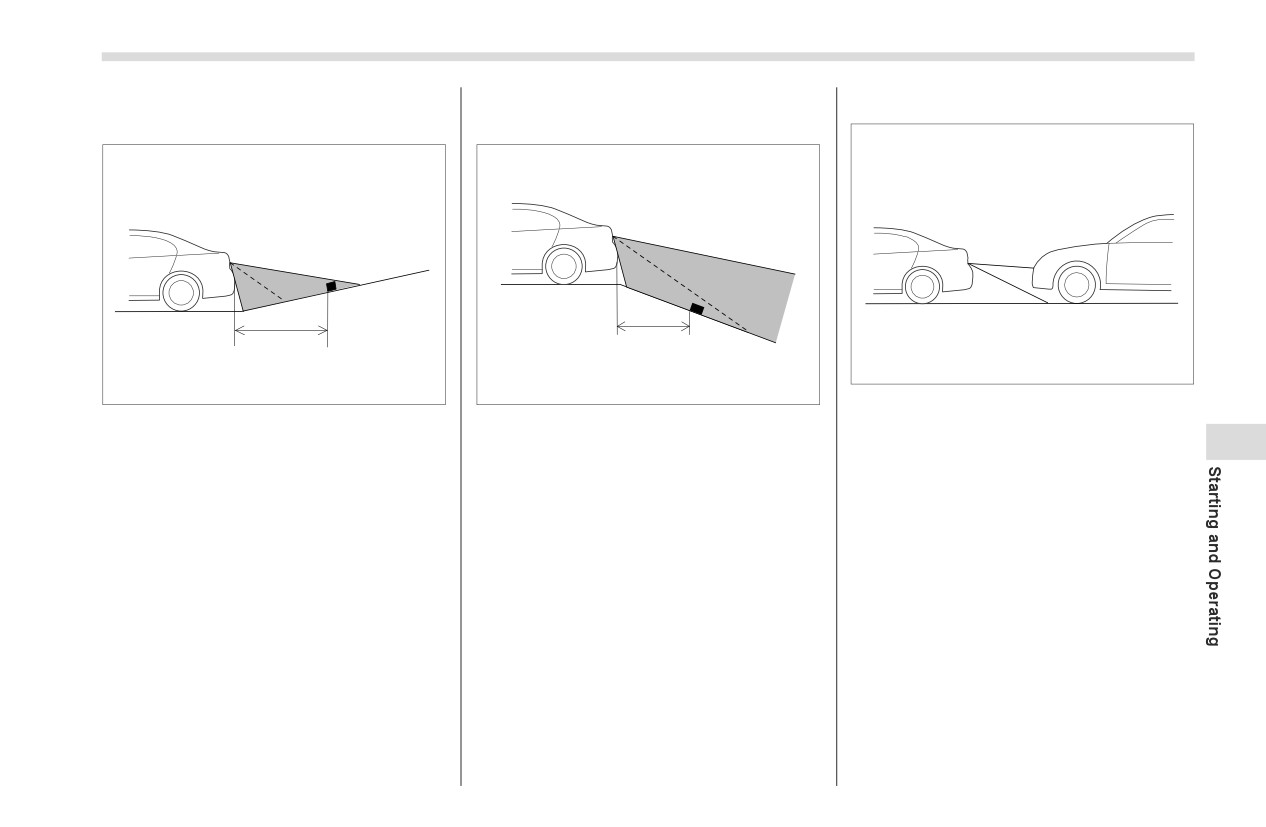
Rear View Camera
267
▽ When there is an upward slope
▽ When there is a downward slope
▼ Feature of distance marker
at the back
at the back
2
1
1
1
601673
601501
601502
1)
3 ft (1 m) line
1)
3 ft (1 m)
1)
3 ft (1 m)
2)
10 ft (3 m) line
7
The distance on the screen looks farther
The distance on the screen looks nearer
The distance marker shows the distance
than the actual distance.
than the actual distance.
on the road. If there is a car or another
object close behind, distance cannot be
NOTE
correctly displayed.
When cargo is loaded, the rear view
distance on the screen looks farther
than the actual distance as in an
upward slope.
268
BSD/RCTA (If Equipped)
7-20. BSD/RCTA (If
The system uses radar sensors for the
The system is designed to assist
following features.
Equipped)
the driver in changing lanes or
reversing safely by monitoring the
The BSD/RCTA consists of rear corner
NOTE
rear and side areas of the vehicle.
radars with Blind Spot Detection and Rear
The BSD/RCTA radar sensor has been
However, you cannot rely on this
Cross Traffic Alert.
certified by the radio wave related laws
system alone in assuring the safety
of the U.S. and other FCC compliant
These functions of BSD/RCTA are the
during a lane change or reversing.
countries, Canada and Mexico. When
systems that detect objects and vehicles
Overconfidence in this system
driving in other countries, certifica-
to the rear and draw attention to the driver
could result in an accident and lead
tion of the country where the vehicle is
when changing a lane or when driving in
to serious injury or death. Since the
driven must be obtained. For certifica-
reverse.
system operation has various lim-
itations, the flashing or illumination
tion in the U.S. and other FCC compli-
WARNING
of the BSD/RCTA approach indica-
ant countries, Canada and Mexico,
tor light may be delayed or it may
refer to "Certification for the BSD/
The driver is responsible for driving
RCTA" ) P274.
not operate at all even when a vehi-
safely. Always be sure to check the
cle is present in a neighboring lane
surroundings with your eyes when
▼ Blind Spot Detection (BSD)
or approaching from either side.
changing lanes or reversing the
vehicle.
The driver is responsible for paying
attention to the rear and side areas
of the vehicle.
■ System Features
1
BSD/RCTA consists of the following func-
tions.
To detect a vehicle in a blind spot on an
adjacent lane or a vehicle approaching at
high speed while driving the vehicle (Blind
701459
Spot Detection)
To detect a vehicle approaching from
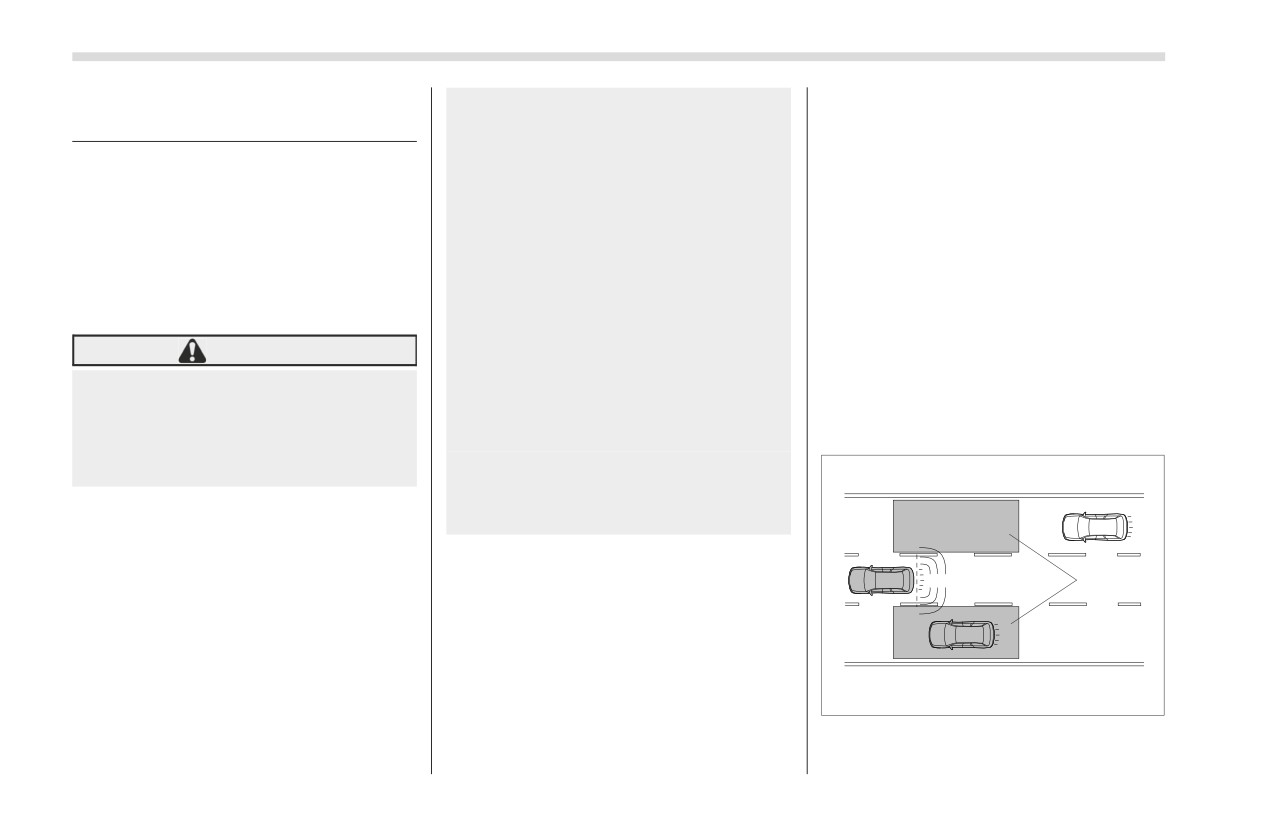
1) Operating range
the right or left while reversing the vehicle
(Rear Cross Traffic Alert)
BSD/RCTA (If Equipped)
269
The system notifies the driver of the pres-
If the system detects a vehicle
driver check the rear and side areas of the
ence of vehicles in its blind spot.
approaching at a high speed in the neigh-
vehicle when moving backward.
If the system detects a vehicle in its
boring lanes, it warns the driver of
If
the system detects a vehicle
blind spot, it warns the driver by illumi-
dangers by illuminating the BSD/RCTA
approaching from either side while moving
nating the BSD/RCTA approach indicator
approach indicator light(s) on the outside
backward, it warns the driver of dangers in
light(s) on the outside mirror(s).
mirror(s).
the following way.
If the driver operates the turn signal
If the driver operates the turn signal
The BSD/RCTA approach indicator
lever in the direction where the BSD/
lever in the direction where the BSD/
light(s) on the outside mirror(s) flashes.
RCTA approach indicator light is illumi-
RCTA approach indicator light is illumi-
A warning buzzer sounds.
nating, the system warns the driver of
nating, the system warns the driver of
An icon appears on the center informa-
dangers by flashing the BSD/RCTA
dangers by flashing the BSD/RCTA
tion display.
approach indicator light.
approach indicator light.
▽ Limitations of the detectability
▽ Lane Change Assist (LCA)
▼ Rear Cross Traffic Alert (RCTA)
of RCTA
Since the detectability of RCTA is limited,
the RCTA may not operate properly in
angled parking.
7
B
1
1
2
701406
701460
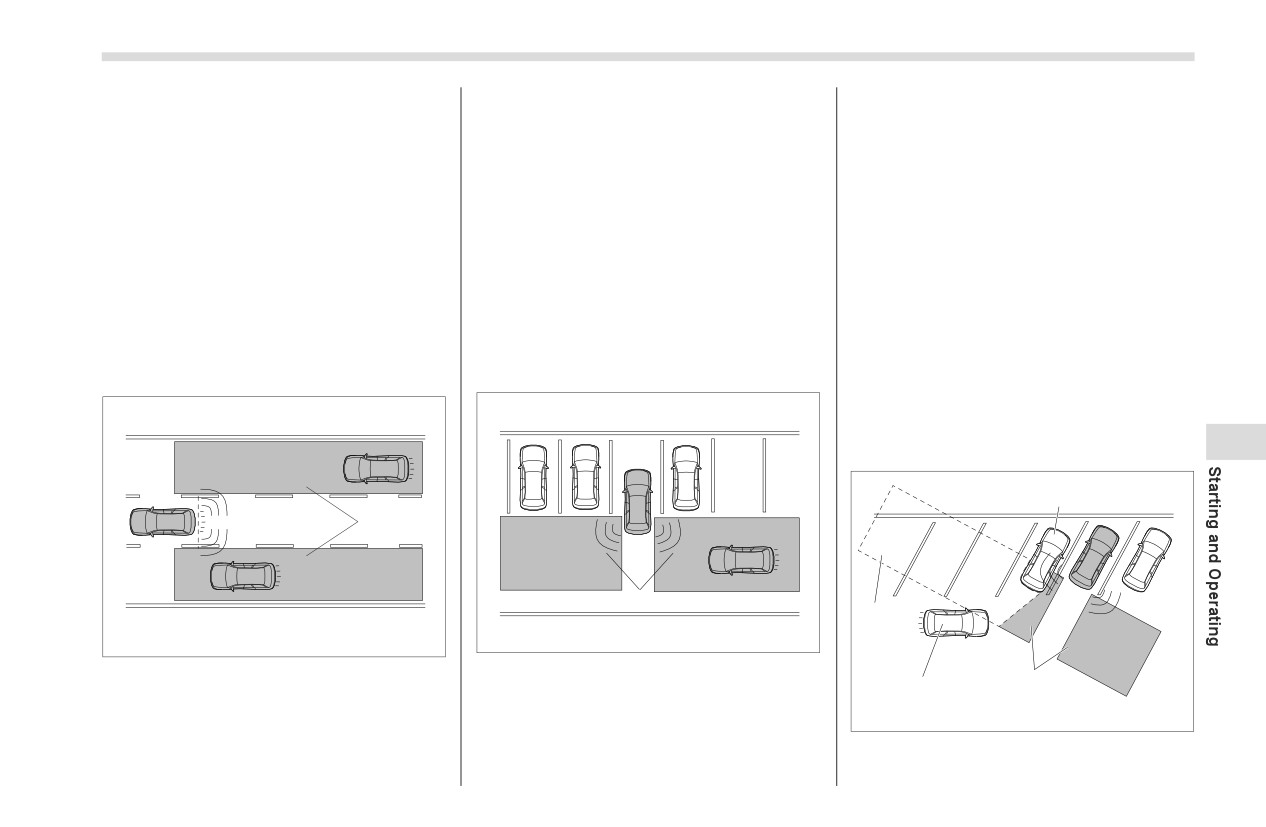
1) Operating range
1) Operating range
1
A
The system notifies the driver of vehicles
The system notifies the driver of another
701818
approaching at a high speed in the neigh-
vehicle approaching from either side when
boring lanes.
driving in reverse. This feature helps the
- CONTINUED -
270
BSD/RCTA (If Equipped)
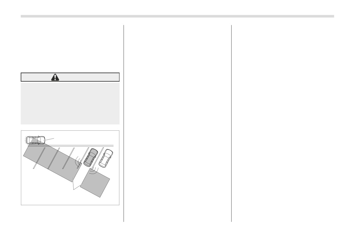
Example 1
C) Vehicle that may be detected
NOTE
1) The detection range of the radar
In the following cases, the BSD/
sensors
NOTE
RCTA will stop operating and the BSD/
2) Area out of detection range of the radar
The system may detect that a vehicle
RCTA warning indicator will appear.
sensors
(C) is passing in front of your vehicle.
-
When a malfunction occurs in
Always be sure to check the
the system, including the BSD/
A) Vehicle that may not be detected
B) Parked vehicle
surroundings with your eyes when
RCTA approach indicator light
reversing the vehicle.
If the BSD/RCTA warning indicator
appears, exercise proper caution. For
WARNING
■ System Operation
details, refer to "BSD/RCTA Warning
An approaching vehicle (A) may not
Indicator" ) P274.
▼ Operating conditions
be detected because the detection
In the following cases, the BSD/
The BSD/RCTA will operate when all of
range is limited by the parked vehi-
RCTA will temporarily stop operating
cle (B). Always be sure to check the
the following conditions are met.
(or may stop operating) and the BSD/
surroundings with your eyes when
The ignition switch is in the “ON” posi-
RCTA OFF indicator will appear.
reversing the vehicle.
tion.
-
When the radar sensor becomes
The BSD/RCTA warning indicator and
significantly misaligned (If the orien-
BSD/RCTA OFF indicator are turned off.
tation of the radar sensor is shifted
for any reason, readjustment is
The vehicle is driven at speeds above
C
required. Have the sensor adjusted
7 mph (12 km/h) (except when reversing).
at a SUBARU dealer.)
The shift lever/select lever is in the “R”
-
When a large amount of snow or
position (RCTA only).
ice sticks to the rear bumper surface
The BSD/RCTA will not operate in the
around the radar sensors
following situations.
-
When the vehicle is driven on a
The BSD/RCTA OFF indicator
snow-covered road or in an environ-
appears.
ment in which there are no objects
The vehicle speed is below 6 mph (10
around (such as in a desert) for a
1
km/h) even when the BSD/RCTA OFF
prolonged period of time
701819
indicator does not appear (except when
-
When the temperature around
reversing).
the radar sensors increases exces-
Example 2
sively due to long driving on uphill
1) The detection
range
of
the
radar
grades in the summer, etc.
sensors
BSD/RCTA (If Equipped)
271
-
When the temperature around
The radar sensors may not detect or
driving in a lane next to the neigh-
the radar sensors becomes
may have difficulty detecting the
boring lane.
extremely low
following vehicles and objects.
-
When the vehicle battery voltage
-
Small motorcycles, bicycles,
■ BSD/RCTA Approach Indi-
lowers
pedestrians, stationary objects on
cator Light/Warning Buzzer
-
When the vehicle voltage
the road or road side, etc.
While the BSD/RCTA is active, the
exceeds the battery voltage rating
-
Vehicles with body shapes that
following item(s) will operate to alert the
The BSD/RCTA will resume operation
the radar may not reflect (vehicles
driver:
once these conditions are corrected,
with lower body height such as a
and the BSD/RCTA OFF indicator will
trailer with no cargo and sports
The BSD/RCTA approach indicator
disappear. However, if the BSD/RCTA
cars)
light (when there are vehicles in the neigh-
OFF indicator appears for a prolonged
-
Vehicles
that
are
not
boring lanes).
period of time, have the system
approaching your vehicle even
The BSD/RCTA approach indicator
inspected at a SUBARU dealer as soon
though they are in the detection area
light and warning buzzer (when a vehicle
as possible.
(either on a neighboring lane to the
is approaching from the left or right side
The detectability of the radar
rear or beside your vehicle when
while your vehicle is reversing)
sensors is restricted. The BSD/RCTA
reversing) (The system determines
the presence of approaching vehi-
▼ BSD/RCTA approach indicator light
7
detection may be impaired and the
system may not operate properly
cles based on data detected by the
under the following conditions.
radar sensors.)
-
When the rear bumper around
-
Vehicles traveling at signifi-
the radar sensors is distorted
cantly different speeds
-
When ice, snow or mud adheres
-
Vehicles driving in parallel at
to the rear bumper surface around
almost the same speed as your
the radar sensors
vehicle for a prolonged time
-
When stickers, etc. are affixed on
-
Oncoming vehicles
the areas of the radar sensors on the
-
Vehicles in a lane beyond the
rear bumper
neighboring lane
-
During adverse weather condi-
-
Vehicles travelling at a signifi-
tions such as rain, snow or fog
cantly lower speed that you are
trying to overtake
702801
-
When driving on wet roads such
On a road with extremely narrow
as snow-covered roads and through
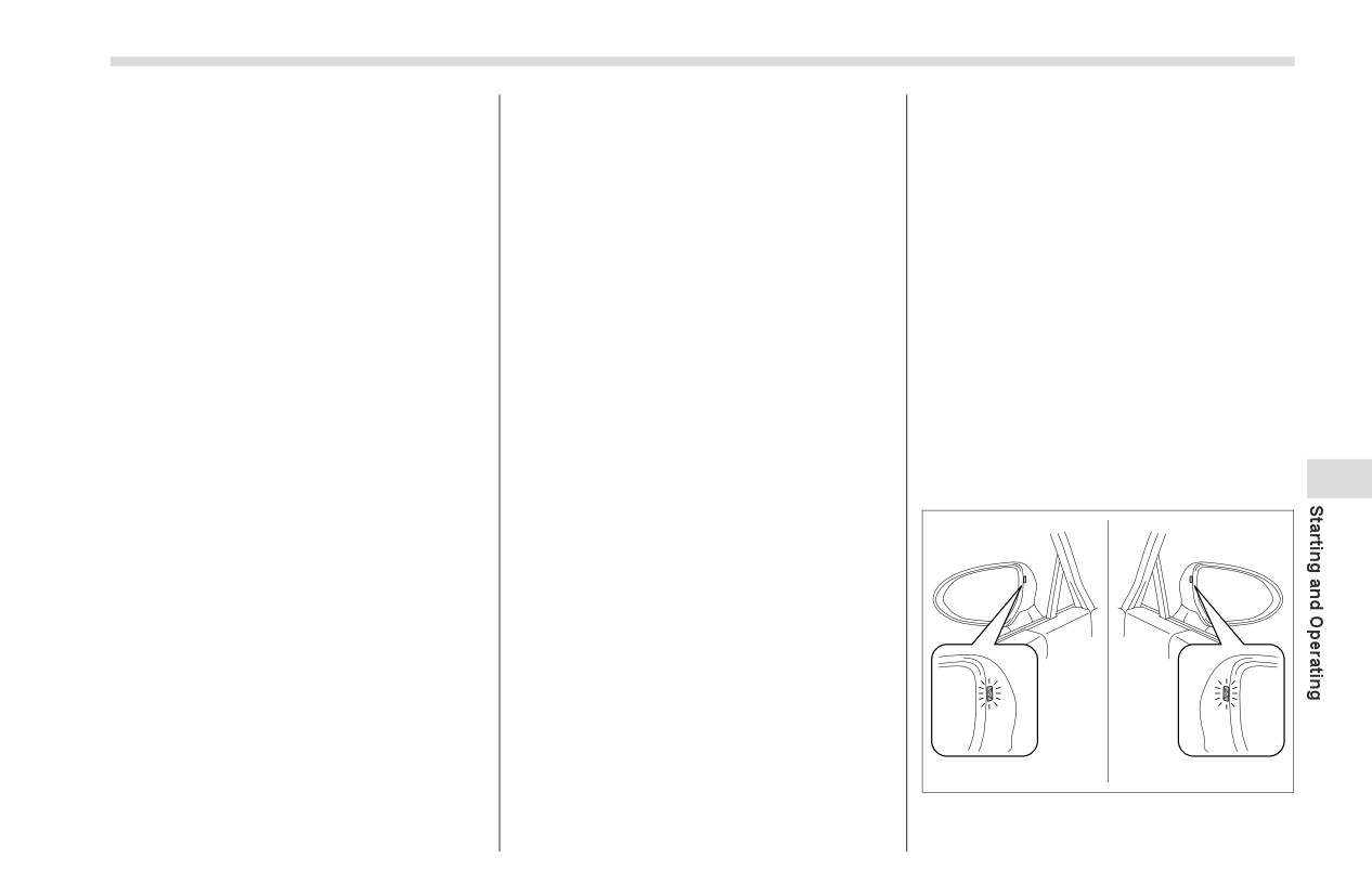
BSD/RCTA approach indicator light
puddles
lanes, the system may detect vehicles
- CONTINUED -
272
BSD/RCTA (If Equipped)
It is mounted on each side of the outside
tion, even if the headlights are turned
- When both your vehicle and a
mirrors.
on, the brightness of the BSD/RCTA
vehicle driving on a neighboring lane
The indicator light will illuminate when a
approach indicator light will not be
are driving on the far side of each lane.
vehicle approaching from behind is
reduced. For details about the illumina-
- When several narrowly-spaced
detected.
tion brightness control dial, refer to
vehicles are approaching in a row
"Illumination Brightness Control"
- In low radius bends (tight bends or
The indicator light will flash to warn the
) P130.
when making turns at an intersection)
driver of dangers under the following
- When there is a difference in height
conditions.
▼ BSD/RCTA approach warning
between your lane and the neighboring
While the indicator light is illuminating,
buzzer (only when reversing)
lane
if the turn signal lever is operated toward
- Immediately after the BSD/RCTA is
A warning buzzer sounds along with
the side in which this light turned on
activated by touching “BSD/RCTA”
flashing of the BSD/RCTA approach indi-
When reversing the vehicle while the
- Immediately after the shift lever/
cator light to warn the driver of dangers.
system detects a vehicle approaching
select lever is shifted to the “R” position
from either side
The setting of the warning buzzer volume
- When extremely heavy cargo is
can be changed by operating the center
loaded in the trunk
▽ BSD/RCTA approach indicator
information display. For details, refer to
During reversing, operation of the BSD/
light dimming function
"Car settings" ) P165.
RCTA approach indicator light and the
When the headlights are turned on, the
warning buzzer may be delayed or the
▼ Safety tips regarding the BSD/
brightness of the BSD/RCTA approach
system may fail to issue these warnings
RCTA approach indicator light/
indicator light will be reduced.
under the following conditions.
warning buzzer
- When backing out of an angled
In the following cases, operation of the
NOTE
parking space
BSD/RCTA approach indicator light and
You may have difficulty seeing the
- When a large-sized vehicle is
the warning buzzer may be delayed or the
BSD/RCTA approach indicator light
parked next to your vehicle
(That
system may fail to issue these warnings.
under the following conditions.
vehicle prevents the propagation of
-
When sunlight shines directly on
- When a vehicle moves to the neigh-
radar waves.)
it
boring lane from a lane next to the
- When reversing on sloped roads
-
When the headlight beams from
neighboring lane
- When reversing at a high speed
a vehicle traveling behind shines
- When driving on a steep incline or
directly on it
on repeated sharp uphill and downhill
While the illumination brightness
grades
control dial is in the fully upward posi-
- When going beyond a pass
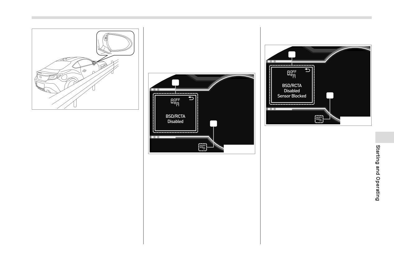
BSD/RCTA (If Equipped)
273
- When the vehicle driving two lanes
▼ System temporary stops due to
away drives on the near side of its lane
reduced radar sensitivity
from your vehicle
■ BSD/RCTA OFF Indicator
1
▼ System temporary stops
1
2
702802
The BSD/RCTA approach indicator
702878
light may illuminate when driving close to
2
solid objects on the road or road side
1) BSD/RCTA temporary stop message
(such as guardrails, tunnels and side-
due to reduced radar sensitivity
7
walls).
2) BSD/RCTA OFF indicator
702877
When turning at an intersection in
This display appears when the detect-
urban areas, or a multilane intersection,
1) BSD/RCTA temporary stop message
ability of the radar sensors is reduced.
the BSD/RCTA approach indicator light
2) BSD/RCTA OFF indicator
Once the condition is corrected, the
may flash.
system will recover from the temporary
This display appears when the system is
If a building or a wall exists in the
stop condition and the indicator will disap-
used at extremely high or low tempera-
reversing direction, the BSD/RCTA
pear.
tures or when abnormal voltage exists.
approach indicator light may flash and the
Once these conditions are corrected, the
If the indicator remains displayed for a
warning buzzer may sound.
prolonged time, have the system
system will recover from the temporary
In the following cases, the system may
inspected at a SUBARU dealer.
stop condition and the indicator will disap-
detect a vehicle driving two lanes away
pear.
from your vehicle.
If the indicator remains displayed for a
- When your vehicle drives on the
prolonged time, have the system
near side of its lane from the corre-
inspected at a SUBARU dealer.
sponding vehicle
- CONTINUED -
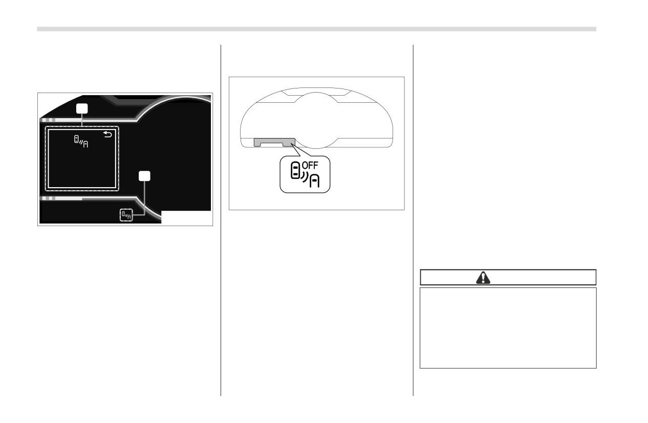
274
BSD/RCTA (If Equipped)
■ BSD/RCTA Warning Indi-
■ To Turn On/Off the BSD/
-
When using a chassis dynamom-
eter or free roller device, etc.
cator
RCTA
-
When running the engine and
▼ System malfunction
making the wheels rotate while
lifting up the vehicle
If the ignition switch is turned to the
1
“OFF” position, the last known status
of the system is maintained. For
example, if the ignition switch is turned
to the “OFF” position with the BSD/
RCTA deactivated, the BSD/RCTA
remains deactivated the next time the
2
ignition switch is turned to the “ON”
position.
702806
■ Certification for the BSD/
702879
BSD/RCTA OFF indicator
RCTA
To turn the BSD/RCTA system on and off,
1) BSD/RCTA malfunction message
The U.S. and other FCC compliant
operate the center information display.
2) BSD/RCTA warning indicator
countries
Refer to "Car settings" ) P165.
FCC ID: OAYSRR3A
This display appears when a malfunction
When the BSD/RCTA system is turned
occurs in the system. Contact a SUBARU
OFF, the BSD/RCTA OFF indicator on the
CAUTION
dealer and have the system inspected.
combination meter display (color TFT) will
illuminate.
FCC WARNING
NOTE
Changes or modifications not
expressly approved by the party
In the following cases, turn off the
responsible for compliance could
BSD/RCTA system. The system may
not operate properly due to blocked
void the user’s authority to operate
radar waves.
the equipment.
-
When a bicycle carrier or other
item is fitted to the rear of the
This device complies with part 15 of the
vehicle
FCC Rules. Operation is subject to the