Subaru BRZ (2023 year). Manual in english - page 7
182
Headlight Beam Leveler
3-12. Headlight Beam Leveler
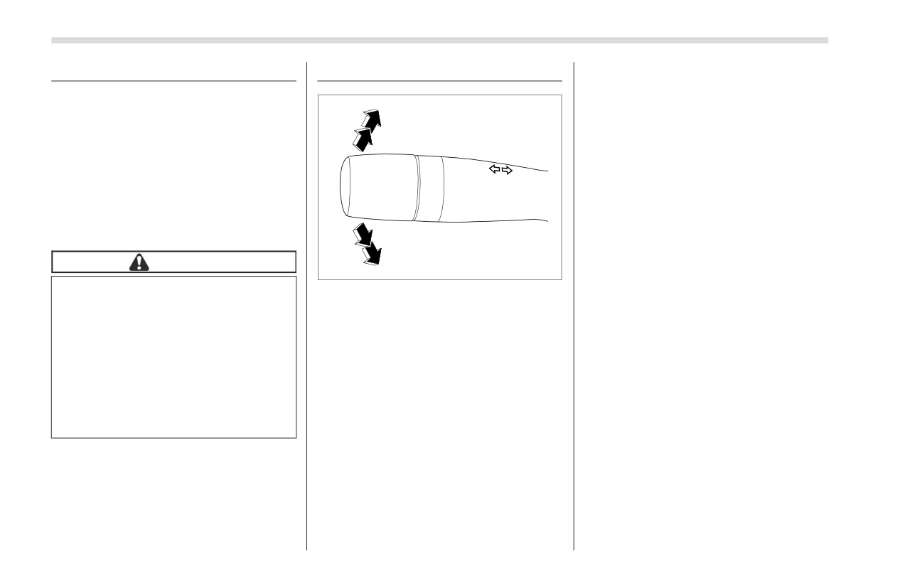
3-13. Turn Signal Lever
To signal a lane change:
1. Push the turn signal lever up or down
The LED headlights produce more light
slightly.
than conventional halogen headlights.
1
2. Hold in the signal lever during the lane
When the vehicle is carrying a heavy load
change.
and the headlight beams are angled
2
upwards, the driver of an oncoming
The turn signal indicator lights will flash in
vehicle may experience glare.
the direction of the turn or lane change.
The lever will return automatically to the
To prevent this, the automatic headlight
neutral position when you release it.
beam leveler adjusts the headlights to the
optimum height automatically depending
on the load the vehicle is carrying.
3
■ One-Touch Lane Changer
To flash the turn signal and turn signal
4
CAUTION
indicator light three times, push the turn
306967
signal lever up or down slightly and imme-
In certain circumstances, the head-
1)
Right turn
diately release it.
lights may become misaligned, and
2)
Lane change right signal
the headlight beam leveler will not
3)
Lane change left signal
NOTE
reset them to the proper angle. This
4)
Left turn
The operational/non-operational set-
may occur after transporting your
To activate the turn signal:
ting of the one-touch lane changer can
vehicle on a flat-bed truck, or if the
be changed by a SUBARU dealer. Con-
vehicle is parked and restarted on
Pushing the turn signal lever up/down and
tact the nearest SUBARU dealer for
different angles. In such cases,
releasing it activates the turn signal. Then
details. The setting can also be
have the headlight alignment
the lever returns to its original position.
changed by operating the center infor-
checked by a SUBARU dealer.
To cancel the turn signal:
mation display. For details, refer to
Push and release the turn signal lever
"Car settings" ) P165
slightly in the opposite direction of the
active turn signal.
Wiper and Washer
183
3-14. Wiper and Washer
In freezing weather, be sure that
Use clean water if windshield
the blade rubbers are not frozen
washer fluid is unavailable. In
to
the windshield before
areas where water freezes in
WARNING
switching on the wipers.
winter, use SUBARU Windshield
In freezing weather, do not use the
Attempting to operate the wiper
Washer Fluid or the equivalent.
windshield washer until the wind-
with the blade rubbers frozen to
Refer to "Windshield Washer
shield is sufficiently warmed by the
the window glass could cause not
Fluid" ) P366.
defroster.
only the blade rubbers to be
Also, when driving the vehicle
damaged but also might cause
when there are freezing tempera-
Otherwise the washer fluid can
3
the wiper motor to fail. If the blade
tures, use non-freezing type
freeze on the windshield, blocking
rubbers are frozen to the window
wiper blades.
your view.
glass, be sure to operate the
Do not clean the wiper blades
defroster before turning on the
with gasoline or a solvent, such
wiper.
as paint thinner or benzine. This
CAUTION
If the wipers stop during opera-
will cause deterioration of the
Do not operate the washer contin-
tion because of ice or some other
wiper blades.
uously for more than 10 seconds,
obstruction on the window, this
or when the washer fluid tank is
might cause the wiper motor to
empty. This may cause over-
fail even if the wiper switch is
NOTE
heating of the washer motor.
turned off. If this occurs,
The windshield wiper motor is
Check the washer fluid level
promptly stop the vehicle in a
protected against overloads by a
frequently, such as at fuel stops.
safe location, turn the ignition
circuit breaker. If the motor operates
Do not operate the wipers when
switch to the “OFF” position and
continuously under an unusually
the windshield is dry. This may
clean the window glass to allow
heavy load, the circuit breaker may trip
scratch the glass, damage the
proper wiper operation.
to stop the motor temporarily. If this
blade rubbers and cause the
happens, park your vehicle in a safe
wiper motor to burn out. Before
location, turn off the wiper switch, and
operating the wiper on a dry wind-
wait for approximately 10 minutes. The
shield always use the windshield
circuit breaker will reset itself, and the
washer.
wipers will again operate normally.
Clean your blade rubbers and
window glass periodically with a
washer solution to prevent streaking,
- CONTINUED -
184
Wiper and Washer
and to remove accumulations of road
rubbers) with new ones. For replace-
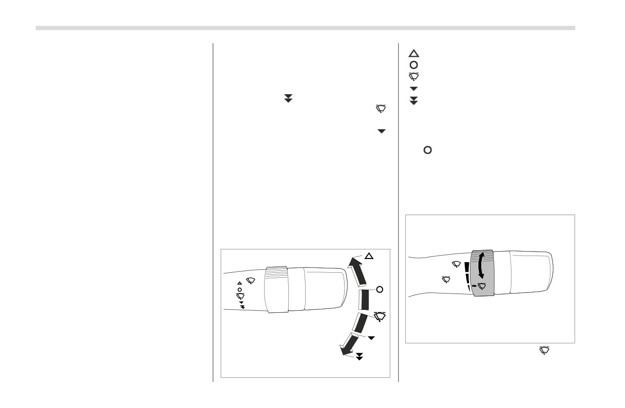
: Mist (for a single wipe)
salt or road film. Operate the wind-
ment instructions, refer to "Replace-
: Off
shield washer for at least 1 second so
ment of Wiper Blades" ) P367.
that washer solution will be sprinkled
If the wipers do not operate in the
: Intermittent
all over the windshield or rear window.
following conditions, turn the wiper
: Low speed
Grease, wax, insects, or other mate-
switch to the “
” position.
: High speed
rial on the windshield or the wiper
-
The wiper switch is in the “
”
blade results in jerky wiper operation
position, however, it does not work.
To turn the wipers on, push the wiper
and streaking on the glass. If you
-
The wiper switch is in the “
”
control lever down.
cannot remove the streaks after oper-
position, however, it does not work.
To turn the wipers off, return the lever to
ating the windshield washer or if the
In these cases, contact your SUBARU
the “
” position.
wiper operation is jerky, clean the
dealer.
For a single wipe of the wipers, push the
outer surface of the windshield using a
lever up. The wipers operate until you
sponge or soft cloth with a neutral
■ Windshield Wiper and
release the lever.
detergent or mild-abrasive cleaner. Do
Washer Switches
not, however, use detergent to clean
▼ Wiper intermittent time control
The wiper operates only when the ignition
the blade rubbers. Use only a sponge
switch is in the “ON” position.
or soft cloth (and no neutral detergent
or mild abrasive cleaner) when you
▼ Windshield wipers
clean the blade rubbers. If you wipe the
rubber of the blade strongly, the black
coating component will peel off, which
will cause the wiper to judder. Also,
after wiping it off, check that the rubber
has not come loose. After cleaning the
window glass and wiper blade rubbers,
be sure to rinse them with clean water.
Rinse the window until the water does
not form beads on the glass. This indi-
301724
cates that the glass is clean.
When the wiper switch is in the “
” posi-
If you cannot eliminate the streaking
even after following this procedure,
tion, turn the dial to adjust the operating
301723
interval of the wiper. The operating
replace the wiper blades
(or blade
Defogger
185
interval can be adjusted in several steps
3-15. Defogger
from the shortest interval to the longest.
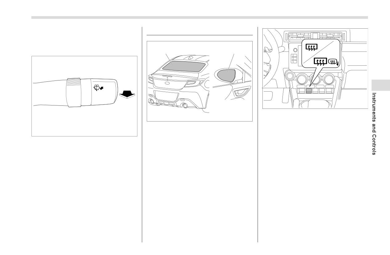
▼ Windshield washer
1
2
3
306819
Rear window and outside mirror
(if
306818
equipped) defogger button
1) Rear window defogger
To activate the defogger system, press
301725
2) Outside mirror defogger (if equipped)
the rear window and outside mirror
defogger button. The rear window
To wash the windshield, pull the wiper
The defogger system is activated only
defogger and outside mirror defogger are
control lever toward you. The washer fluid
when the ignition switch is in the “ON”
activated simultaneously. The indicator
sprays until you release the lever. The
position.
light on the button illuminates while the
wipers operate while you pull the lever.
defogger system is activated.
To turn them off, press the button again.
They also turn off when the ignition switch
is turned to the “ACC” or “OFF” position.
The defogger system will automatically
shut off after approximately 15 minutes. If
the rear window and outside mirrors have
been cleared before that time, press the
button to turn them off. If defrosting or
defogging is not complete, you have to
press the button to turn them on again.
- CONTINUED -
186
Mirrors
It is possible to set the defogger system
3-16. Mirrors
■ Auto-Dimming Mirror/
for the continuous operation mode by
operating the center information display.
Always check that the inside and outside
Compass with HomeLink®
For details, refer to "Car settings" ) P165.
mirrors are properly adjusted before you
(Dealer Option)
start driving.
CAUTION
1
■ Inside Mirror
To prevent the battery from being
discharged, do not operate the
defogger system continuously
for any longer than necessary.
Do not use sharp instruments or
window cleaner containing abra-
sives to clean the inner surface of
the rear window. They may
3
damage the conductors printed
2
1
2
on the window.
304867
1)
Display
NOTE
2)
HomeLink® buttons
305310
While the defogger system is in the
3)
Switch
continuous operation mode, if the bat-
1) Normal position
tery voltage drops below the permissi-
2) Anti-glare position
During nighttime driving,
the auto-
ble level, continuous operation of the
dimming feature senses distracting glare
defogger system is canceled and the
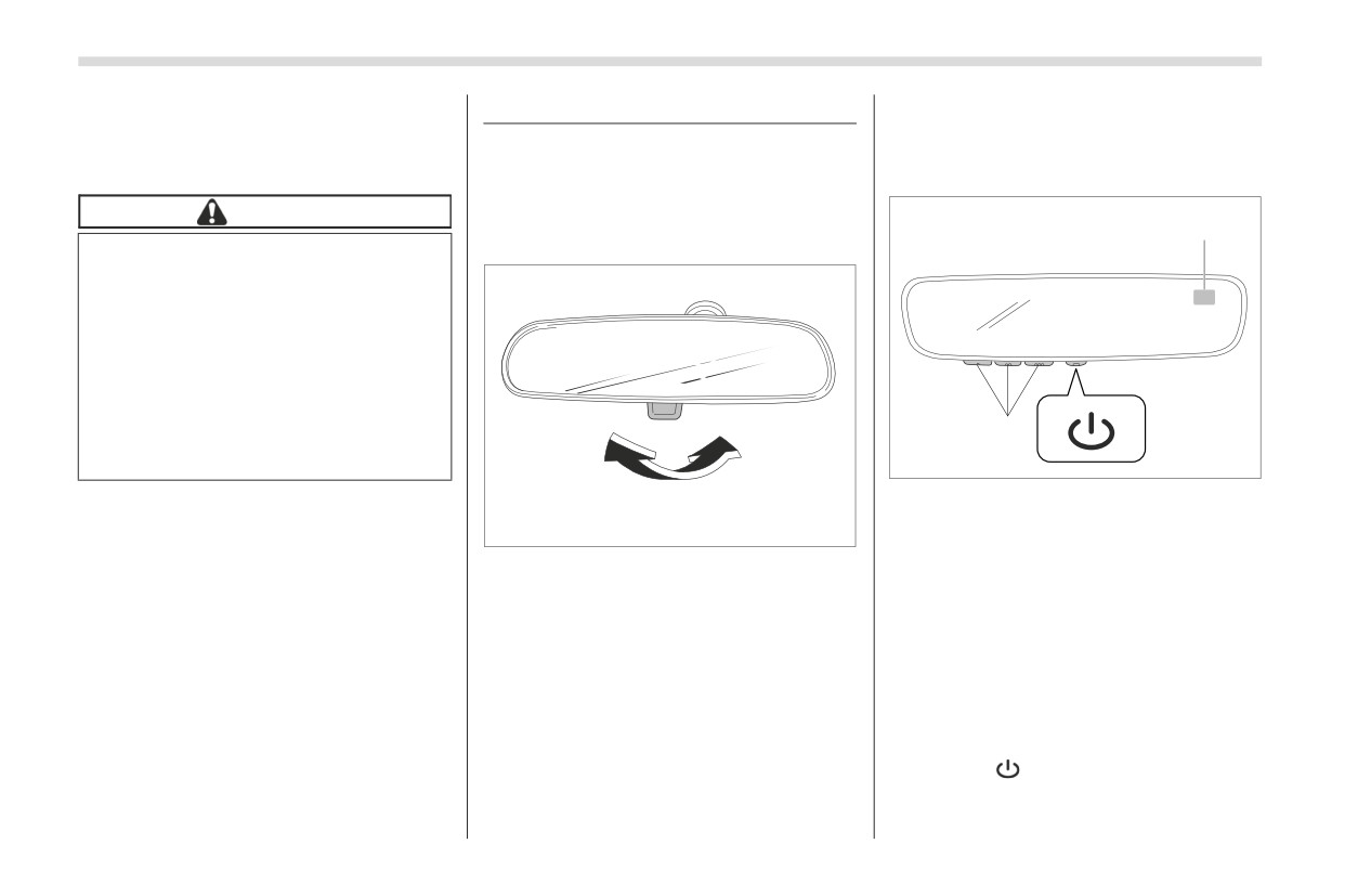
Push the tab on the mirror for normal use.
from vehicle headlights behind you and
system stops operating.
To reduce glare from the headlights of the
automatically dims to eliminate the glare
vehicle behind you, pull the tab to the anti-
and help preserve your vision.
glare position.
▼ To Operate the Auto-Dimming
Feature
Press the “
” switch to turn the auto-
dimming feature on/off. The auto-dimming
feature is enabled when the switch’s
green LED indicator is on. The auto-
Mirrors
187
dimming feature will default to on with
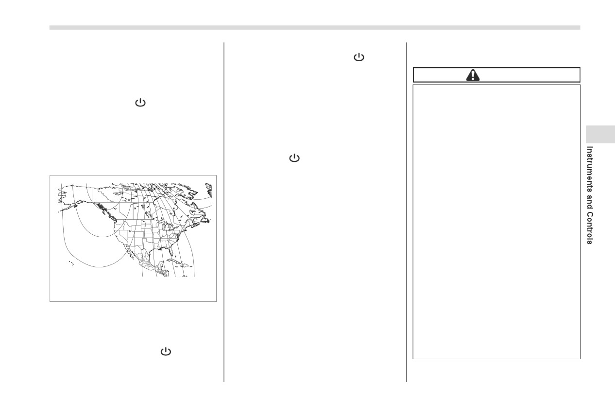
Once the zone number appears in
and
each ignition cycle.
the display, toggle the
“
” switch
again until your current location zone
▼ To Operate the Compass Feature
number appears. After you stop
CAUTION
pressing the switch, your new zone
1. To turn the compass feature on/off,
Before programming HomeLink®
number will be saved. Within a few
press and hold the “
” switch for more
to a garage door opener or gate
seconds, the display will show a
than 3 seconds or until the display turns
operator, make sure that people
compass direction.
on/off. The compass feature will default to
and objects are out of the way of
4. If the vehicle’s magnetics have
on with each ignition cycle.
the device to prevent potential
changed or if the compass appears inac-
3
2. If the display reads “C”, slowly drive
harm or damage.
curate, recalibrate the compass. Press
the vehicle in circles until compass is cali-
and hold the “
” switch for more than 9
When programming a garage
brated.
seconds or until a
“C” appears in the
door opener, it is advised to park
display. Once a “C” appears in the display,
outside of the garage.
slowly drive the vehicle in circles until
Do not use HomeLink® with any
3
15
compass is calibrated.
garage door opener that lacks
14
safety stop and reverse features
13
▼ HomeLink® Wireless Control
4
as required by U.S. federal safety
12
System
11
standards
(this includes any
5
10
6
8
9
7
garage door opener model manu-
The HomeLink® Wireless Control System
factured before April 1, 1982). A
provides a convenient way to replace up
garage door that cannot detect an
to three hand-held radio frequency
object signaling the door to stop
remotes used to activate devices such as
and reverse does not meet
gate operators, garage door openers,
304866
current U.S. federal safety stan-
entry door locks, security systems, even
dards.
home lighting. The below steps are
Compass calibration zones
generic programming instructions; for
It is also recommended that a new
3. To adjust for compass zone variance:
Genie and Sommer garage door openers
battery be placed in the hand-
Find your current location and zone
held remote (garage door opener
please go directly to the HomeLink®
number on the map.
remote) of the device for quicker
website. Additional information and
Press and hold the “
” switch for
and more accurate training.
programming videos can be found at
more than 6 seconds or until a zone
number appears in the display.
- CONTINUED -
188
Mirrors
Turn the ignition switch to the
▽ Programming a New HomeLink®
slowly (if not, refer to "Erasing HomeLink®
“ON” or “ACC” position before
button
buttons" ) P191).
programming and/or operating
HomeLink®.
1
Keep the hand-held remote
(garage door opener remote) of
the device you are programming
for use in other vehicles as well
as for future HomeLink®
programming. It
is
also
suggested that upon the sale of
the vehicle, the programmed
1
HomeLink® buttons be erased for
2
security purposes. Refer to
304868
304869
"Erasing HomeLink® buttons"
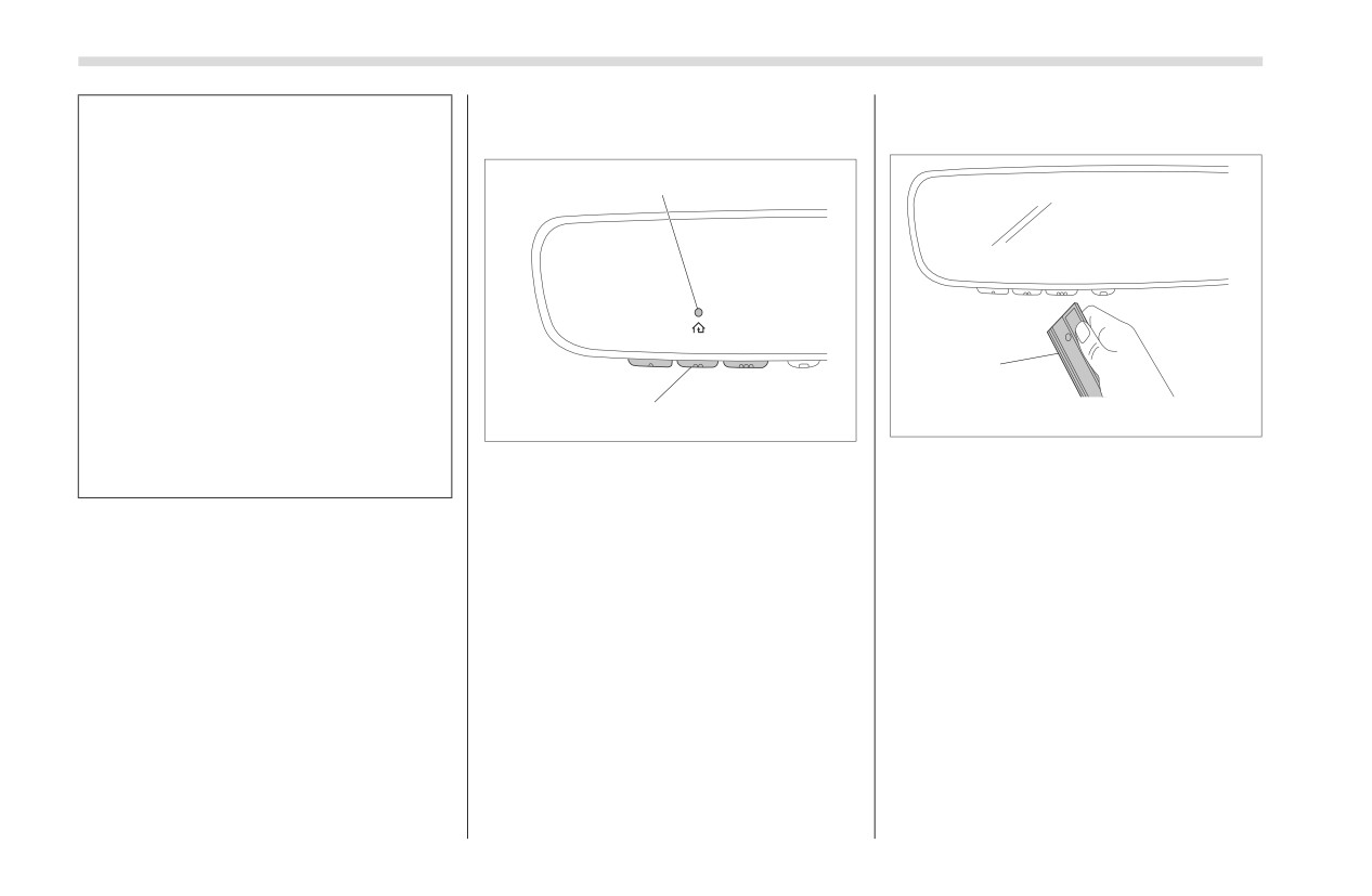
1)
Indicator Light
1) Garage door opener remote
) P191.
2)
HomeLink® buttons
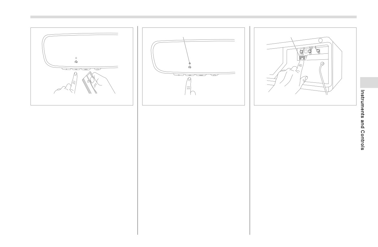
2. Position the hand-held remote (garage
door opener remote) 1 to 3 inches (2 to 8
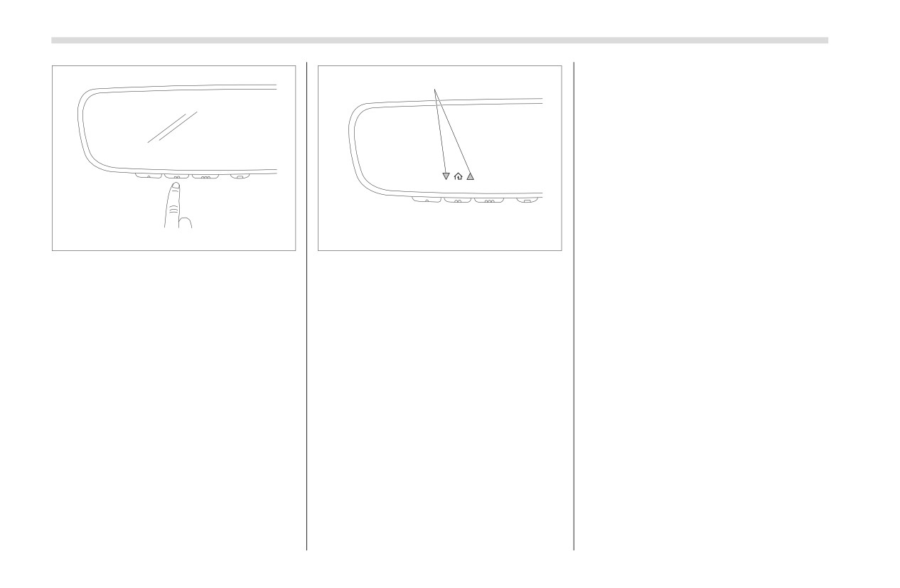
1. Press and release
the
HomeLink®
cm) away from the HomeLink® button that
button that you would like to program. The
you would like to program.
HomeLink® indicator light will flash orange
NOTE
Some hand-held remotes (garage door
opener remotes) may actually train
better at a distance of 6 to 12 inches
(15 to 30 cm). Keep this in mind if you
have difficulty with the programming
process.
Mirrors
189
1
1
3
304870
304871
304872
1) Indicator Light
1)
“Learn” button
3. While the HomeLink® indicator light is
flashing orange, press and hold the hand-
4. Press the HomeLink® button that you
5. At the garage door opener motor,
held remote button. Continue pressing the
(security gate motor, etc.) locate the
would like to program and observe the
hand-held remote button until the
“Learn”,
“Smart”, or
“Program” button.
indicator light.
HomeLink® indicator light changes from
This can usually be found where the
If the indicator light remains
orange to green. You may now release
hanging antenna wire is attached to the
constant green, your device should
the hand-held remote button.
motor-head unit (see the device’s manual
operate when the HomeLink® button is
to identify this button). The name and
NOTE
pressed. At this point, if your device
color of the button may vary by manufac-
operates, programming is complete.
Some devices may require you to
turer.
If the indicator light rapidly flashes
replace this
“Programming a New
green, firmly press, hold for two
HomeLink® button” step 3 with proce-
NOTE
seconds and release the HomeLink®
dures noted in the “Gate Operator /
A ladder and/or second person may
button up to three times to complete
Canadian Programming” section.
simplify the following steps.
the programming process. At this point
Refer to "Gate Operator/Canadian Pro-
6. Firmly press and release the “Learn”,
if your device operates, programming
gramming" ) P190.
“Smart”, or “Program” button. You now
is complete. If the device does not
have 30 seconds in which to complete
operate, continue with the next step of
step 7.
the programming instructions.
- CONTINUED -
190
Mirrors
quit) after several seconds of transmis-
1
sion, which may not be long enough for
HomeLink® to pick up the signal during
programming. Similar to this Canadian
law, some U.S. gate operators are
designed to
“time-out” in the same
manner. The indicator LED on the hand-
held remote will go off when the device
times out, indicating that it has finished
transmitting.
If you live in Canada or you are having
304873
304874
difficulties programming a gate operator
or garage door opener by using the
7. Return to the vehicle and firmly press,
1) Status Indicators
programming
procedures,
replace
hold for
2 seconds and release the
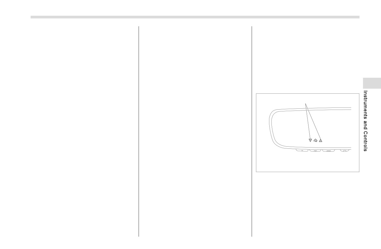
8. If status indicator arrows appear next
“Programming a New HomeLink® button”
HomeLink® button up to three times. At
to the indicator light, please refer to
step 3 with the following:
this point programming is complete and
"Garage Door Two-Way Communication"
While the HomeLink® indicator light is
your device should operate when the
) P191.
flashing orange, press and release
HomeLink® button is pressed and
In the event that there are still program-
(“cycle”) your device’s hand-held remote
released.
ming difficulties or questions, additional
every two seconds until the HomeLink®
HomeLink® information and programming
indicator light changes from orange to
videos can be found at
green. You may now release the hand-
www.HomeLink.com and
held remote button.
Genie and Sommer garage door openers
NOTE
please go directly to the HomeLink®
If programming a garage door opener
website.
or gate operator, it is advised to
unplug the device during the “cycling”
▽ Gate Operator/Canadian
process to prevent possible overheat-
Programming
ing.
Canadian radio-frequency laws require
transmitter remote signals to “time-out” (or
Mirrors
191
Proceed with
“Programming a New
▽ Reprogramming a Single
HomeLink® has the capability of receiving
HomeLink® button” step 4 to complete.
HomeLink® button
this communication from the garage door
opener at a range up to 820 feet (250 m).
To program a previously trained button,
▽ Using HomeLink®
Range may be reduced by obstacles such
follow these steps:
as houses or trees. You may have to slow
To operate, simply press and release the
1. Press and hold the desired
your vehicle speed to successfully receive
programmed HomeLink® button. Activa-
the garage door opener communication.
HomeLink® button. DO NOT release the
tion will now occur for the trained device
button.
(i.e. garage door opener, gate operator,
▽ Programming Two-Way
security system, entry door lock, home/
2. The indicator light will begin to slowly
3
Communication
office lighting, etc.). For convenience, the
flash orange after
20 seconds. The
hand-held remote of the device may also
HomeLink® button can be released at this
1
be used at any time.
point. Proceed with “Programming a New
HomeLink® button”- step 3.
▽ Erasing HomeLink® buttons
3. If you do not complete the program-
To erase programming from the three
ming of a new device to the button, it will
buttons
(individual buttons cannot be
revert to the previously stored program-
erased but can be “reprogrammed” as
ming.
outlined below), follow the step noted:
▽ Garage Door Two-Way Commu-
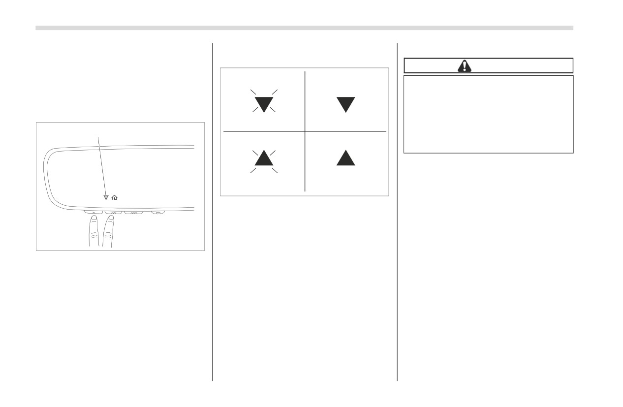
Press and hold the two outer HomeLink®
nication
buttons for at least 10 seconds. The LED
indicator will change from continuously lit
HomeLink® has the capability of commu-
304874
to rapidly flashing. Release both buttons.
nicating with your garage door opener.
Do not hold for longer than 20 seconds.
1) Status Indicators
HomeLink® can receive and display
HomeLink® is now ready to be
“closing” or
“opening” status messages
Within
5 seconds after programming a
programmed at any time beginning with
from compatible garage door opener
new
HomeLink® button, both of
“Programming a New HomeLink® button”-
systems. At any time, HomeLink® can
HomeLink’s garage door status indicators
step 1.
also recall and display the last recorded
will flash rapidly green indicating that the
status communicated by the garage door
garage door two-way communication has
opener to indicate your garage door being
been enabled. If your garage door status
“closed” or “opened”.
indicators flashed, two-way communica-
tion programming is complete.
- CONTINUED -
192
Mirrors
If the garage door status indicators do not
status of your garage door opener with
U.S.-spec. models
arrow indicators (see below).
flash, additional HomeLink® information
and programming videos can be found
CAUTION
online at www.HomeLink.com and
1
2
FCC WARNING
Changes or modifications not
▽ Using Two-Way Communication
expressly approved by the party
responsible for compliance could
1
void the user’s authority to operate
3
4
the equipment.
304876
1) Garage Door Opener CLOSING
(Blinking Orange)
2) Garage Door Opener CLOSED (Solid
Green)
304875
3) Garage Door Opener OPENING
(Blinking Orange)
1) Status Indicator
4) Garage Door Opener OPENED (Solid
Green)
Recall and display (at any time) the last
recorded garage door status message
▽ Certification
communicated to HomeLink® by simulta-
In the event that there are still program-
neously pressing HomeLink® buttons 1
ming difficulties or questions, additional
and 2 for
2 seconds. HomeLink® will
HomeLink® information and programming
display the last recorded status for
3
videos can be found at
seconds.
If two-way communication programming is
successful, HomeLink® will display the
by calling the toll-free HomeLink-hotline at
1-800-355-3515.

Mirrors
193
Canada-spec. models
3
306210
306211
306210
HomeLink® and the HomeLink® house
are registered trademarks of Gentex
Corporation.
- CONTINUED -
194
Mirrors
■ Outside Mirrors
NOTE
WARNING
The mirrors can also be adjusted man-
▼ Remote control mirror switch
When
programming
the
ually.
HomeLink® Wireless Control
System, you may be operating a
garage door opener or other
device. Make sure that people
and objects are out of the way of
the garage door or other device to
prevent potential harm or
damage.
Do not use the HomeLink® Wire-
less Control System with a
garage door opener that lacks the
safety stop and reverse feature as
306821
required by applicable safety
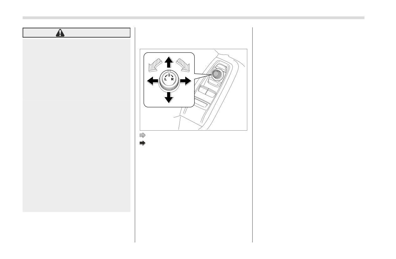
: Select side to adjust
standards. A garage door opener
: Direction control
which cannot detect an object,
signaling the door to stop and
The remote control mirrors operate when
reverse, does not meet these
the ignition switch is in the “ON” or “ACC”
safety standards. Using a garage
position.
door opener without these
1. Turn the control switch to the side that
features increases risk of serious
you want to adjust. “L” is for the left mirror,
injury or death. For more informa-
“R” is for the right mirror.
tion, consult the HomeLink®
2. Move the control switch in the direction
website at www.HomeLink.com
you want to move the mirror.
or call 1-800-355-3515.
3. Return the control switch to the neutral
position to prevent unintentional opera-
tion.
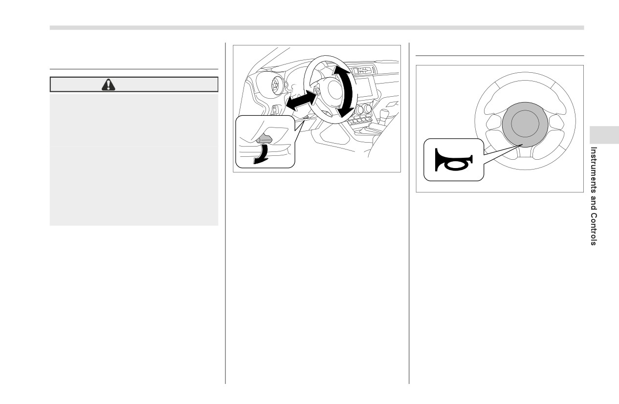
Tilt/Telescopic Steering Wheel
195
3-17. Tilt/Telescopic Steering
3-18. Horn
Wheel
WARNING
2
1
Do not adjust the steering wheel
tilt/telescopic
position while
driving. This may cause loss of
vehicle control and result in
3
personal injury.
If the lever cannot be raised to the
fixed position, adjust the steering
3
306823
wheel again. It is dangerous to
1) Tilt adjustment
drive without locking the steering
306824
2) Telescopic adjustment
wheel. This may cause loss of
3) Tilt/telescopic lock lever
To sound the horn, push the horn pad.
vehicle control and result in
personal injury.
1. Adjust the seat position. Refer to
"Front Seats" ) P30.
2. Pull the tilt/telescopic lock lever down.
3. Move the steering wheel to the desired
level.
4. Pull the lever up to lock the steering
wheel in place.
5. Make sure that the steering wheel is
securely locked by moving it up and down,
and forward and backward.
Climate Control
4-1. Ventilator Control
198
4-6. Operating Tips for Heater and Air
Center Ventilators
198
Conditioner
204
Side Ventilators
198
Cleaning Ventilator Grille
204
4-2. Climate Control Panel
198
Efficient Cooling after Parking in Direct Sunlight
204
4-3. Automatic Climate Control Operation
200
Lubrication Oil Circulation in the Refrigerant
Sensors
200
Circuit
204
4-4. Manual Climate Control
201
Checking Air Conditioning System before Summer
Airflow Mode Selection
201
Season
204
Temperature Control
202
Cooling and Dehumidifying in High Humidity and
Fan Speed Control
202
Low Temperature Weather Condition
205
Air Conditioner Control
202
Air Conditioner Compressor Shut-Off When
4
Air Inlet Selection
203
Engine Is Heavily Loaded
205
To Turn Off the Climate Control System
203
Refrigerant for Your Climate Control System
205
4-5. Defrosting
203
4-7. Air Filtration System
205
Replacing the Cabin Air Filter
206
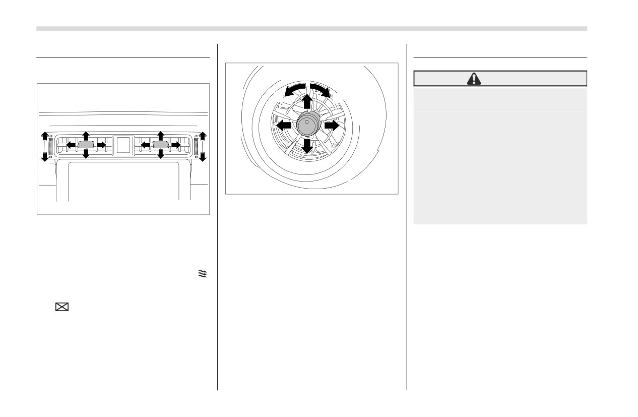
198
Ventilator Control
4-1. Ventilator Control
■ Side Ventilators
4-2. Climate Control Panel
■ Center Ventilators
WARNING
The cooling function operates
1
2
only when the engine is running.
Do not leave children or adults
1
1
who would normally require the
support of others alone in your
vehicle. Pets should not be left
alone either. On hot, sunny days,
2
2
temperatures in a closed vehicle
could quickly become high
403483
enough to cause severe or
1) Open
possibly fatal injuries to people
403482
2) Close
or animals.
1) Open
2) Close
To adjust the flow direction, move the tab.
Move the tab to adjust the flow direction.
To open the ventilator, turn the center
grille open/close wheel upward to the “
”
position.
To close it, turn the wheel downward to
the “
” position.
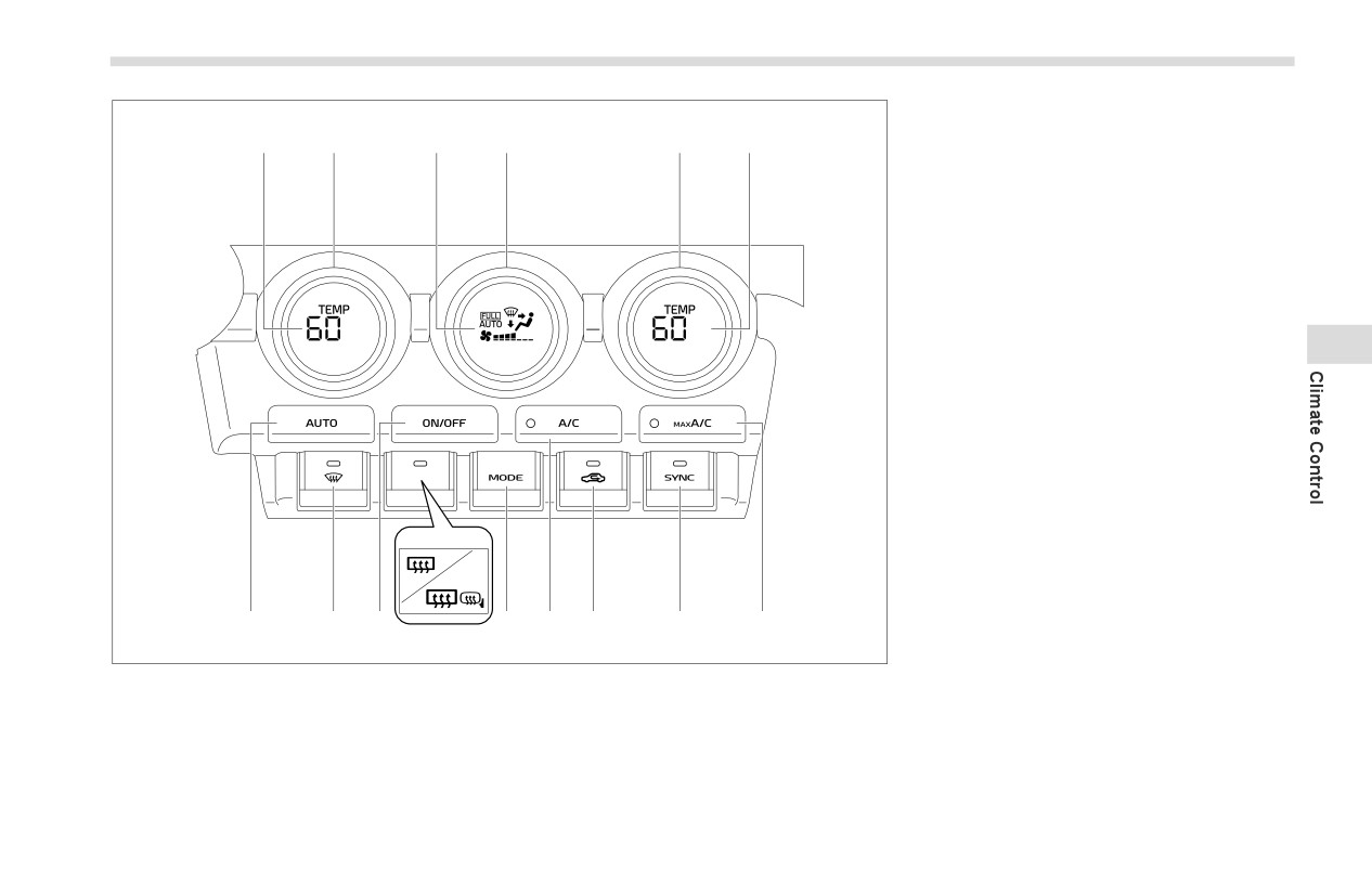
Climate Control Panel
199
1)
Set temperature indicator (driver’s side)
2)
Temperature control dial (driver’s side)
1
2
3
4
5
6
(Refer to "Temperature Control"
) P202.)
3)
Climate control mode indicator
4)
Fan speed control dial (Refer to "Fan
Speed Control" ) P202.)
5)
Temperature control dial
(front
passenger’s side) (Refer to "Tempera-
ture Control" ) P202.)
6)
Set temperature indicator
(front
passenger’s side)
4
7)
MAX A/C button (Refer to "MAX A/C
mode" ) P202.)
8)
SYNC button (Refer to "SYNC mode"
) P202.)
9)
Air inlet selection button (Refer to "Air
Inlet Selection" ) P203.)
10) Air conditioner button
(Refer to "Air
Conditioner Control" ) P202.)
11) Airflow mode selection button (Refer to
12
"Airflow Mode Selection" ) P201.)
12) Rear window defogger button and
outside mirror defogger button
(if
equipped)
(Refer to "Defogger"
15
14
13
11
10
9
8
7
) P185.)
403484
13) ON/OFF button (Refer to "To Turn Off
the Climate Control System" ) P203.)
14) Defroster button (Refer to "Defrosting"
) P203.)
15) AUTO button
(Refer to "Automatic
Climate Control Operation" ) P200.)
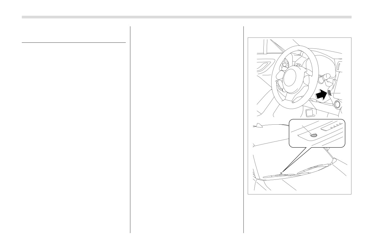
200
Automatic Climate Control Operation
4-3. Automatic Climate
The controllable temperature range
■ Sensors
may vary depending on the regional
Control Operation
specifications of the vehicle.
If you operate any of the buttons on
When this mode is selected, the fan
the control panel other than the ON/
speed, airflow mode, air-inlet control, and
OFF button, rear window defogger
air conditioner operation are automatically
button, SYNC button and temperature
controlled. To activate this mode, perform
control dial(s) during FULL AUTO
the following.
mode operation, the “FULL” indicator
1. Press the AUTO button. The FULL
light on the control panel will turn off
AUTO mode is selected and the “FULL
and the “AUTO” indicator light will
1
AUTO” indicator light on the display illumi-
remain illuminated. You can then
nates.
manually control the system as desired
2. Set the preferred temperature using
using the button you operated. To
the temperature control dial.
change the system back to the FULL
AUTO mode, press the AUTO button.
2
NOTE
To turn off the climate control system,
Operate the automatic climate
press the ON/OFF button. Then the air
control system when the engine is
inlet selection will be set to the following.
running.
When the air inlet selection is set to
Even when cooling is not necessary,
auto mode: Outside air circulation
the air conditioner will automatically
When the air inlet selection is set to
turn on if the temperature is set much
manual mode: No change
lower than the current outlet air
When the ignition switch is changed to the
temperature. Even in this case, the “A/
“OFF” or “ACC” position from “ON”, the air
C” indicator light on the control panel
inlet mode will automatically change to the
403485
illuminates
outside air mode regardless of whether it
The air conditioner may not operate
1)
Interior air temperature sensor
is the auto mode or manual mode.
in the following cases:
2)
Solar sensor
-
When the cabin temperature is
low
The automatic climate control
system
-
When the ambient temperature
employs several sensors. These sensors
are delicate. If they are treated incorrectly
decreases close to 32°F (0°C)
Manual Climate Control
201
and become damaged, the system may
4-4. Manual Climate Control
not be able to control the interior tempera-
ture correctly. To avoid damaging the
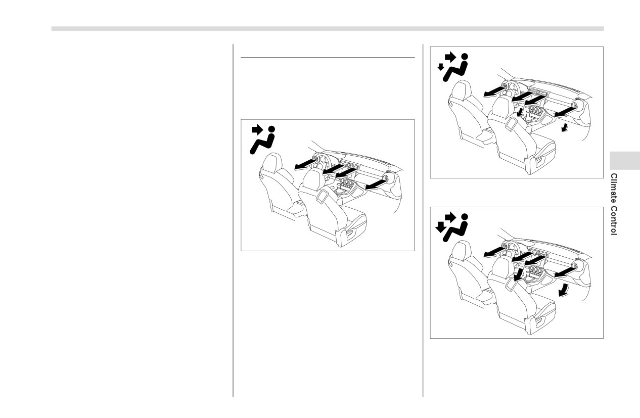
■ Airflow Mode Selection
sensors, observe the following precau-
Select the airflow mode using the airflow
tions:
mode selection button.
Do not subject the sensors to impact.
Airflow modes are as follows.
Keep water away from the sensors.
Do not cover the sensors.
4
403488
Ventilation 2: Instrument panel outlets and
foot outlets
403486
Ventilation: Instrument panel outlets
403487
Bi-level: Instrument panel outlets and the
foot outlets
- CONTINUED -
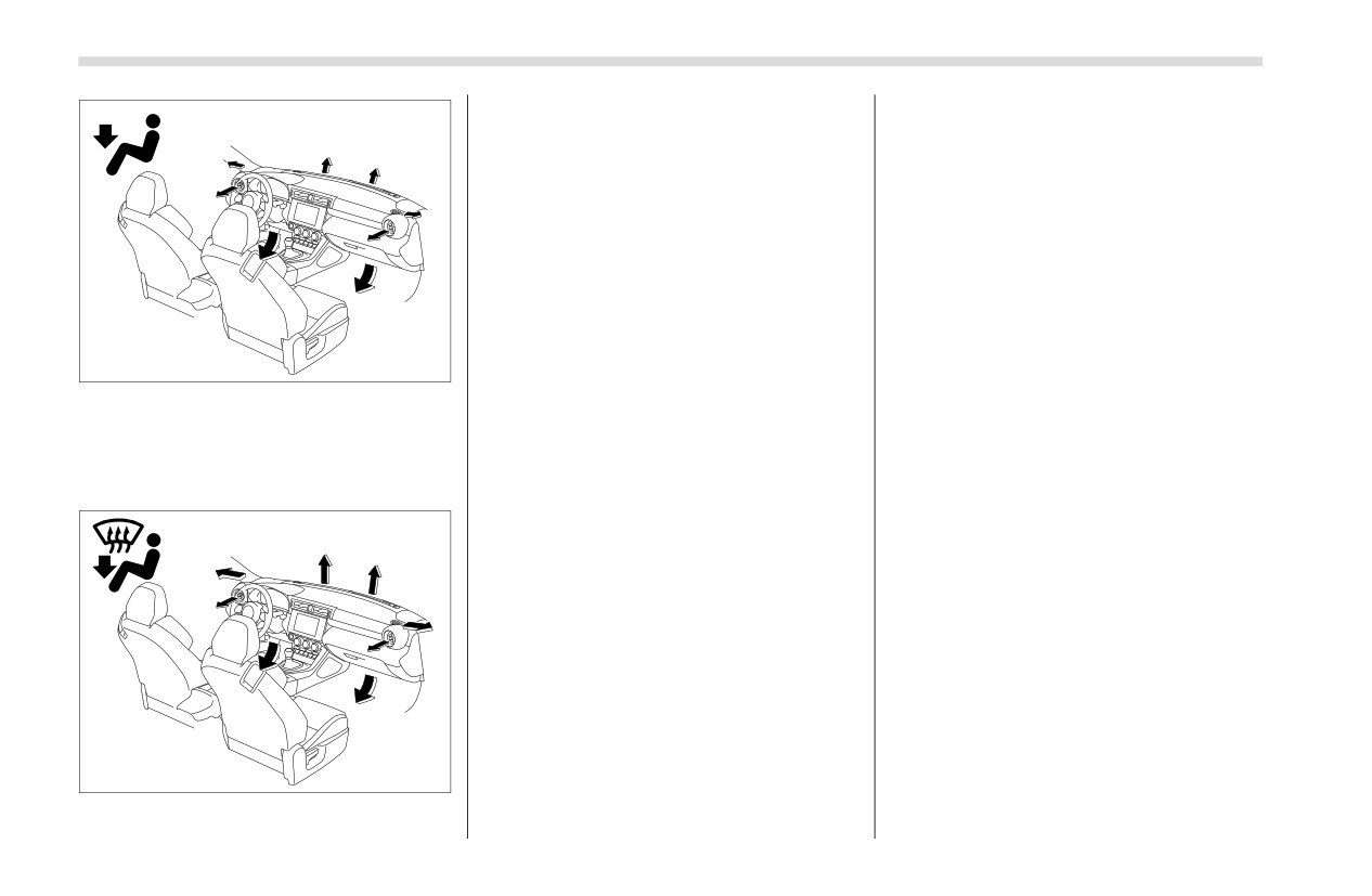
202
Manual Climate Control
Heat-def: Windshield defroster outlets,
▼ SYNC mode
foot outlets and both side outlets of the
When the SYNC mode is turned on, both
instrument panel
the driver’s and front passenger’s side
temperatures are synchronized using the
■ Temperature Control
driver’s side temperature control dial.
Turn the temperature control dial to set
Press the SYNC button to turn on the
the preferred interior temperature.
SYNC mode. The SYNC button indicator
will illuminate.
NOTE
Press the SYNC button again or turn the
The controllable temperature range
front passenger’s side temperature
may vary depending on the regional
control dial to cancel the SYNC mode.
403489
specifications of the vehicle.
The SYNC button indicator will not illumi-
Heat: Foot outlets, both side outlets of the
nate. In this case, temperature control on
▼ MAX A/C mode
the driver’s side and front passenger’s
instrument panel and some through wind-
For quicker cooling, press the MAX A/C
side is separated.
shield defroster outlets (A small amount of
air flows to the windshield and both side
button.
The temperature will be controlled individ-
windows to prevent fogging.)
When the MAX A/C mode is on, the
ually using the driver’s and front
following settings will be changed auto-
passenger’s temperature control dials.
matically.
The air conditioner will turn on.
■ Fan Speed Control
The temperature will be set on the
Select the preferred fan speed by turning
lowest.
the fan speed control dial.
The fan speed will be set on the
maximum speed.
■ Air Conditioner Control
The air inlet will be set to the recircula-
The air conditioner operates only when
tion mode.
the engine is running.
The airflow mode setting will be set to
Press the air conditioner button while the
the ventilation mode.
fan is in operation to turn on the air condi-
403490
tioner. When the air conditioner is on, the
To turn off MAX A/C mode and return the
“A/C” indicator light illuminates.
previous setting, press the MAX A/C
button again.
Defrosting
203
To turn off the air conditioner, press the
button to the OFF position in the following
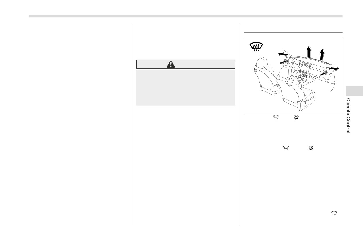
4-5. Defrosting
button again. The indicator light will turn
cases.
off.
- When the road is no longer dusty
- When the interior has cooled to a
NOTE
comfortable temperature
For efficient defogging or dehumidify-
ing in cold weather, turn on the air
WARNING
conditioner. However, if the ambient
temperature decreases to approxi-
Continued operation in the recircu-
mately 32°F (0°C), the air conditioner
lation mode may fog up the win-
and dehumidification system may not
dows. Switch to the outside air
circulation mode as soon as the
4
work properly.
outside dusty condition clears.
■ Air Inlet Selection
403491
Select the air inlet by pressing the air inlet
NOTE
Select the “
” or “
” mode to defrost
selection button.
When outside air circulation is
or dehumidify the windshield and the side
Recirculation:
selected, the system may automati-
door windows.
cally adjust the air inlet setting
When the indicator light on the air inlet
depending on such factors as the tem-
selection button illuminates, interior air is
NOTE
perature setting, the temperature
recirculated inside the vehicle. Press the
When the “
” or “
” mode is
inside the vehicle, or conditions out-
air inlet selection button to the ON position
selected, the air conditioner operates
side the vehicle.
in the following cases.
automatically regardless of the posi-
- When driving on a dusty road
tion of the air conditioner button to
■ To Turn Off the Climate
- When you want cooling perfor-
defrost the windshield more quickly.
Control System
mance to increase (for example, in
However, the indicator on the air condi-
particularly hot weather)
To turn off the climate control system,
tioner button may not illuminate. At the
Outside air circulation:
press the ON/OFF button.
same time, the air inlet selection is
automatically set to the outside air
When the indicator light on the air inlet
circulation mode.
selection button does not illuminate,
After defrosting the windshield by
outside air is drawn into the passenger
compartment. Press the air inlet selection
pressing the defroster button “
”,
pressing the button again returns the
- CONTINUED -
204
Operating Tips for Heater and Air Conditioner
system to the setting that had been
4-6. Operating Tips for Heater
■ Efficient Cooling after
selected before the defroster was acti-
and Air Conditioner
Parking in Direct Sunlight
vated.
After parking in direct sunlight, drive with
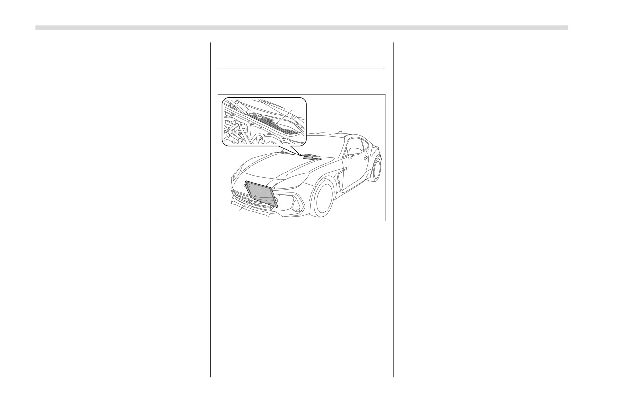
■ Cleaning Ventilator Grille
the windows open for a few minutes to
allow outside air to circulate into the
1
heated interior. This results in quicker
cooling by the air conditioner. Keep the
windows closed during the operation of
the air conditioner for maximum cooling
efficiency.
■ Lubrication Oil Circulation in
the Refrigerant Circuit
Operate the air conditioner compressor at
a low engine speed (at idle or low driving
403492
speeds) a few minutes each month during
2
the off-season to circulate its oil.
1)
Front ventilator inlet grille
2)
Condenser
■ Checking Air Conditioning
Always keep the front ventilator inlet grille
System before Summer
free of snow, leaves, or other obstructions
Season
to ensure efficient heating and defrosting.
Check the air conditioner unit for refrig-
Since the condenser is located in front of
erant leaks, hose conditions, and proper
the radiator, this area should be kept
operation each spring. Have the air condi-
clean because cooling performance is
tioning system checked by your SUBARU
impaired by any accumulation of insects
dealer.
and leaves on the condenser.
Air Filtration System
205
■ Cooling and Dehumidifying
■ Refrigerant for Your Climate
4-7. Air Filtration System
in High Humidity and Low
Control System
Your vehicle’s air conditioning system is
Temperature Weather Condi-
equipped with an air filtration system.
tion
Replace the cabin air filter according to
Under certain weather conditions (high
the replacement schedule found in the
relative humidity, low temperatures, etc.)
“Warranty and Maintenance Booklet”.
a small amount of water vapor emission
1
This schedule should be followed to main-
from the air outlets may be noticed. This
tain the filter’s dust collection ability.
Under extremely dusty conditions, the
condition is normal and does not indicate
filter should be replaced more frequently.
any problem with the air conditioning
Have your filter checked or replaced by
4
system.
your SUBARU dealer. For replacement,
use only a genuine SUBARU air filter kit.
■ Air Conditioner Compressor
Shut-Off When Engine Is
403493
CAUTION
Heavily Loaded
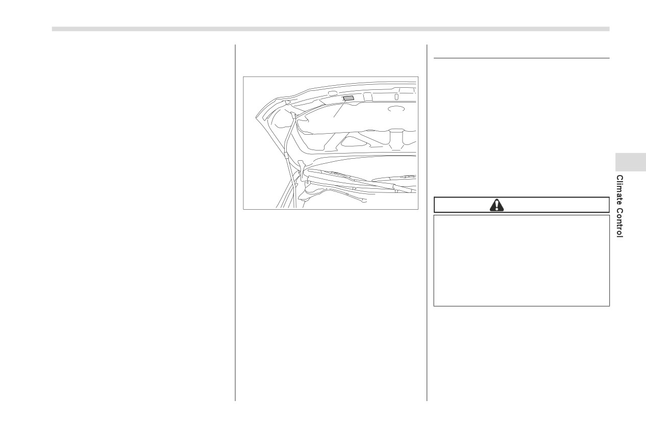
1) Air conditioner label
Contact your SUBARU dealer if the
To improve acceleration and gas mileage,
Your air conditioner uses ozone friendly
following occurs, even if it is not yet
the air conditioner compressor is
refrigerant R-1234yf (HFO-1234yf).
time to change the filter.
designed to temporarily shut off during air
conditioner operation whenever the accel-
Before adding, changing or checking the
Reduction of the airflow through
erator is fully depressed such as during
refrigerant, check the air conditioner label
the vents.
rapid acceleration or when driving on a
in the location shown in the illustration to
Windshield gets easily fogged or
steep upgrade.
confirm the type of refrigerant is used in
misted.
your vehicle.
Consult your SUBARU dealer for service.
NOTE
Repairs needed as a result of using the
The filter can influence the air condi-
wrong refrigerant are not covered under
tioning, heating and defroster perfor-
warranty.
mance if not properly maintained.
- CONTINUED -
206
Air Filtration System
■ Replacing the Cabin Air Filter
doing this, be careful not to damage the
hinge.
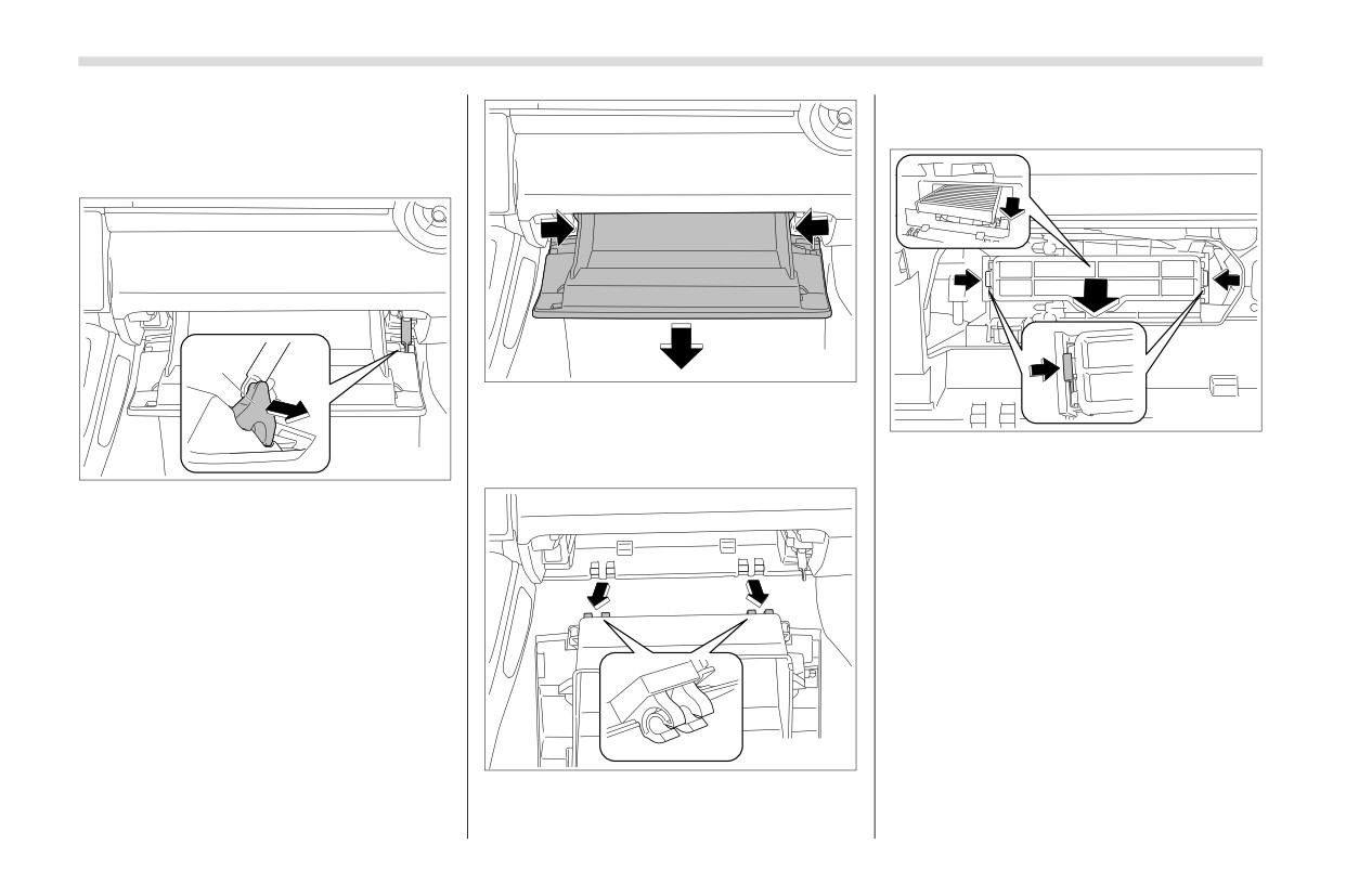
1. Remove the glove box.
(1) Open the glove box.
403495
1
(3) Push both sides of the glove box
403497
inward to unlock the stoppers and then
pull down the glove box as far as it will
2. Remove the cabin air filter according
403594
go.
to the following procedure in order to
1) Link pocket
prevent dust on the air cleaner from falling
to the inside of its housing.
(2) Remove the link pocket from the
(1) Pinch both tabs and remove the
glove box.
filter cover.
(2) Gently tilt down the end of the filter
and slowly pull it out 0.4 in (1 cm).
(3) Slowly pull out the rest of the filter.
403496
(4) Pull out the glove box horizontally
and remove the hinge portion. When
Air Filtration System
207
4
403498
403499
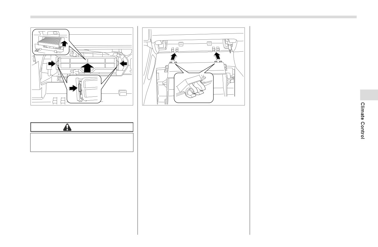
3. Replace the cabin air filter with a new
4. Reinstall the glove box in the reverse
one and then reinstall the cover.
order of removal.
5. Close the glove box.
CAUTION
The arrow mark on the filter must
point UP.
Audio
5-1. Antenna
210
5-2. Audio Set
210
Roof Antenna
210
5
210
Antenna
5-1. Antenna
5-2. Audio Set
If your vehicle is equipped with a genuine
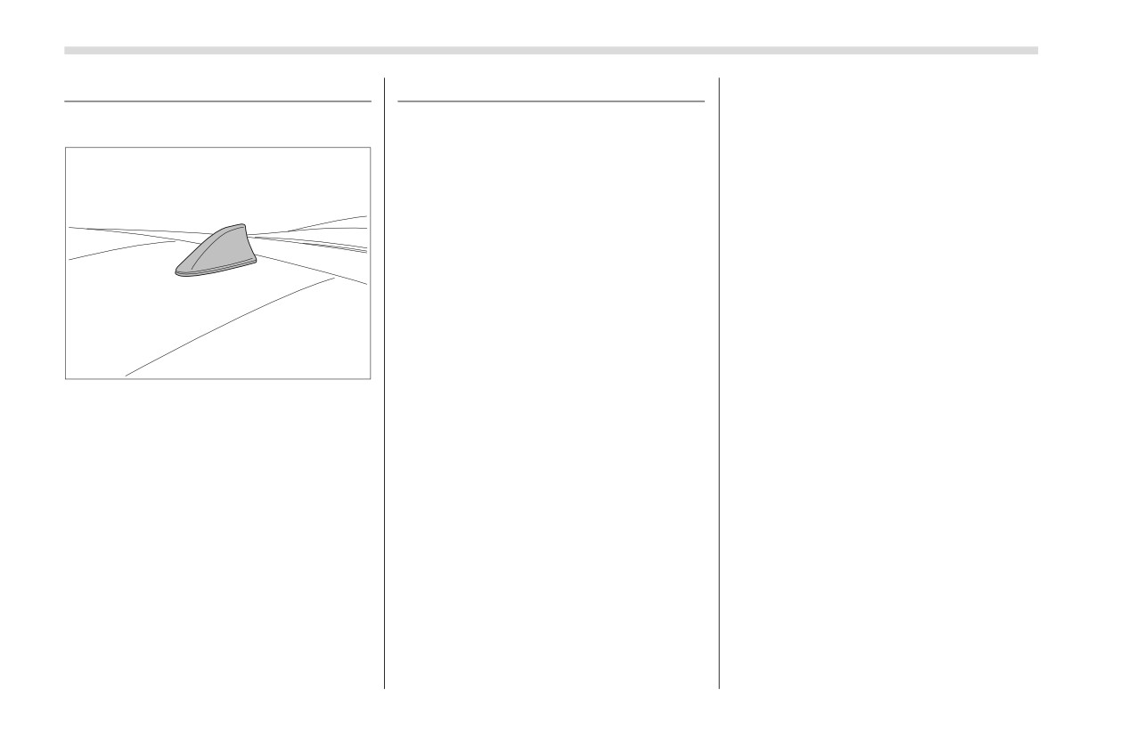
■ Roof Antenna
SUBARU audio system, refer to the sepa-
rate audio Owner’s Manual for details.
501618
The roof antenna is installed on the roof.
Interior Equipment
6-1. Interior Light
212
6-4. Bottle Holders
215
Map Lights
212
6-5. Accessory Power Outlets
215
OFF Delay Timer
212
6-6. USB Power Supply
216
6-2. Sun Visors
213
How to Use the USB Power Supply
217
Vanity Mirror with Light (If Equipped)
213
6-7. Ashtray (Dealer Option)
217
6-3. Storage Compartment
213
6-8. Floor Mat
218
Glove Box
214
6-9. Under-Floor Storage Compartment
Center Console
214
(models with the flat tire repair kit)
219
6
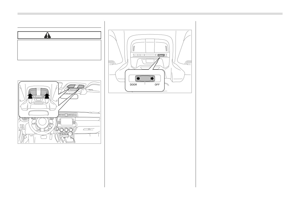
212
Interior Light
6-1. Interior Light
▼ Door interlock switch
■ OFF Delay Timer
Map lights have an automatic illumination
CAUTION
function.
When the interior light switch is set to the
When leaving your vehicle, make
“DOOR” position, the light will automati-
sure the lights are turned
off
to
cally turn on and off depending on the
avoid battery discharge.
locking and unlocking of the doors, the
opening and closing of the doors, as well
■ Map Lights
as the position of the ignition switch.
▼ Map light switches
NOTE
The setting for the period of time in
1
602245
which the lights remain on (OFF delay
timer) can be changed by a SUBARU
1) Door interlock switch
dealer. Contact your SUBARU dealer
for details. Also, the setting can be
The door interlock switch has the following
changed by operating the center infor-
positions.
mation display. For details, refer to
OFF: The map lights do not illuminate
"Car settings" ) P165.
automatically in conjunction with a door
opening. However, the lights can be
turned on manually by pressing the map
light lens.
602244
DOOR: The map lights illuminate auto-
To turn on the map light, press the lens.
matically when any of the doors (other
To turn it off, press the lens again.
than the trunk lid) is opened even while
the map light is off. Several seconds after
all of the doors (other than the trunk lid)
are closed, the map lights gradually turn
off. For details, refer to "OFF Delay Timer"
) P212.
Sun Visors
213
6-2. Sun Visors
6-3. Storage Compartment
CAUTION
Keep the storage compartment
closed when it is not being used.
If left open, in the event of sudden
braking, etc., stowed items may
fly out, possibly leading to an
accident.
Do not store the following items
in the storage compartment.
602246
Otherwise, it may cause a fire or
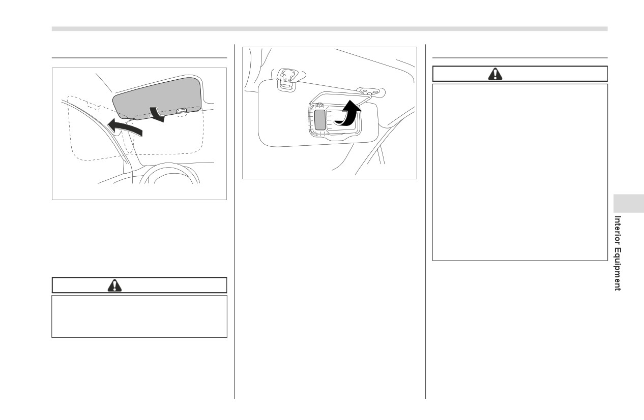
To use the vanity mirror, swing down the
accident.
601182
sun visor and open the vanity mirror
-
Spray cans, containers with
To block out glare, swing down the visors.
cover.
6
flammable or corrosive liquids
To use the sun visor at a side window,
The lights beside the vanity mirror illumi-
or any other dangerous items.
swing it down and move it sideways.
nate when the mirror cover is opened.
-
Plastic or other heat-vulner-
able or flammable articles
■ Vanity Mirror with Light (If
NOTE
such as a lighter.
Equipped)
Use of the vanity mirror light for a long
period of time while the engine is not
CAUTION
running can cause battery discharge.
Keep the vanity mirror cover closed
while the car is being driven to
avoid being blinded by glare.
- CONTINUED -