Subaru Ascent (2023 year). Manual in english - page 6
Rear gate
153
To pause the opening rear gate:
To close the rear gate:
! By manual operation
Briefly press either of the following buttons
Briefly press either of the following but-
To open the rear gate:
while the rear gate is being opened.
tons.
Lift up the rear gate when the rear gate is at
. Rear gate opener button
. Rear gate opener button
midway position. The rear gate will open
. Power rear gate button on the inside
. Power rear gate button on the inside
automatically.
edge of the rear gate
edge of the rear gate
To close the rear gate:
Pull down the rear gate when the rear gate
If you press the power rear gate button
If you press the power rear gate button
is opened. The rear gate will close auto-
again, the rear gate will close. You can
again, the rear gate will open.
open the rear gate by pressing the power
matically.
To Lock the doors using the power rear
rear gate button briefly while the rear gate
gate lock button:
NOTE
is being closed.
Carry the access key fob, and press the
If the rear gate is moved slowly, it may
power rear gate lock button. All doors, the
not operate automatically open or
rear gate and the fuel filler lid are locked,
close.
and the rear gate will be closed. Also, the
! Manual operation
hazard warning flashers will flash once,
and an electronic chirp will sound once.
NOTE
Using the power rear gate operation is
NOTE
recommended. Manual operation will
. By pushing the power rear gate lock
require physical effort.
button for more than 2 seconds, all
doors are locked, however, the auto
The power rear gate can be closed
manually. Refer to
“Manual rear gate”
door closing function of the rear
FP148.
gate will be canceled.
. If any of the doors is not fully closed,
NOTE
the outside warning chime sounds
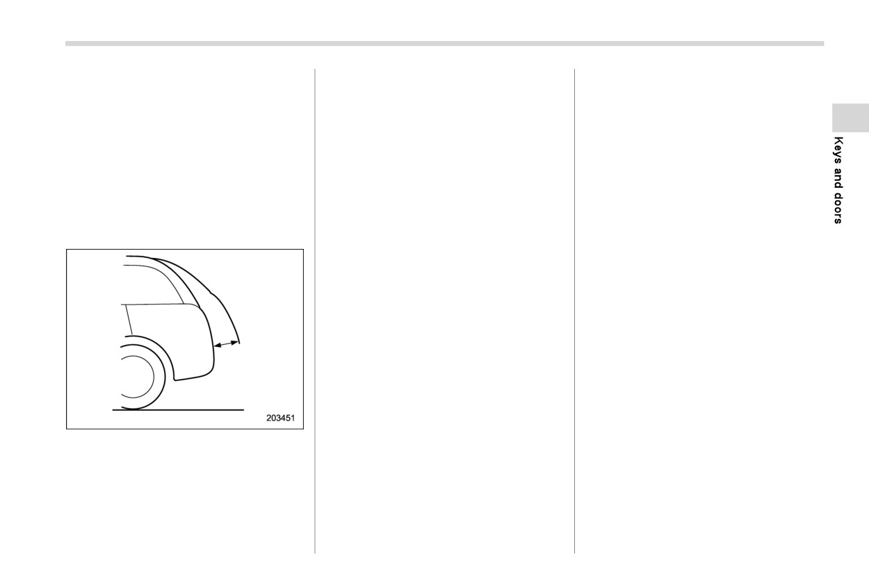
The rear gate cannot be paused when it
five times to alert you that the doors
is in the approximately 2 in (5 cm) range
are not properly closed.
from the fully closed position. The
system will ignore any button operation
and the rear gate will continue to open.
- CONTINUED -
154 Rear gate
! Memory function
NOTE
1. Check that “Power Rear Gate Memory”
is on. Refer to “Car settings” FP215.
The preferred rear gate height can be
. Register the rear gate height to turn
2. Press and hold any of the power rear
registered.
on the “Power Rear Gate Memory”
gate button.
automatically. For details, refer to
! Registration of the rear gate
“Car settings” FP215.
height
. To change the registered height,
NOTE
To register the rear gate height, perform
perform the registering procedure
The rear gate will open to the position
the following procedures.
again.
that is stored in the memory function
1.
Open the rear gate and stop it at the
. It is possible to register the height
even if the rear gate is opened by the
preferable height.
from approximately 2 in (5 cm) or
reverse function.
more from the completely closed
position.
! Reverse function
! Deactivation of the memory func-
WARNING
tion
Deactivate the memory function to open
Do not let parts of your body get
the rear gate fully. Perform either of the
caught when operating the re-
following operation to deactivate the mem-
verse function. If the reverse
ory function.
function does not operate for
some reason, this may lead to
- Deactivate the
“Power Rear Gate
serious injury or accidents.
Memory” function on the center infor-
mation display. Refer to “Car settings”
The reverse function may not
FP215.
operate if foreign objects are
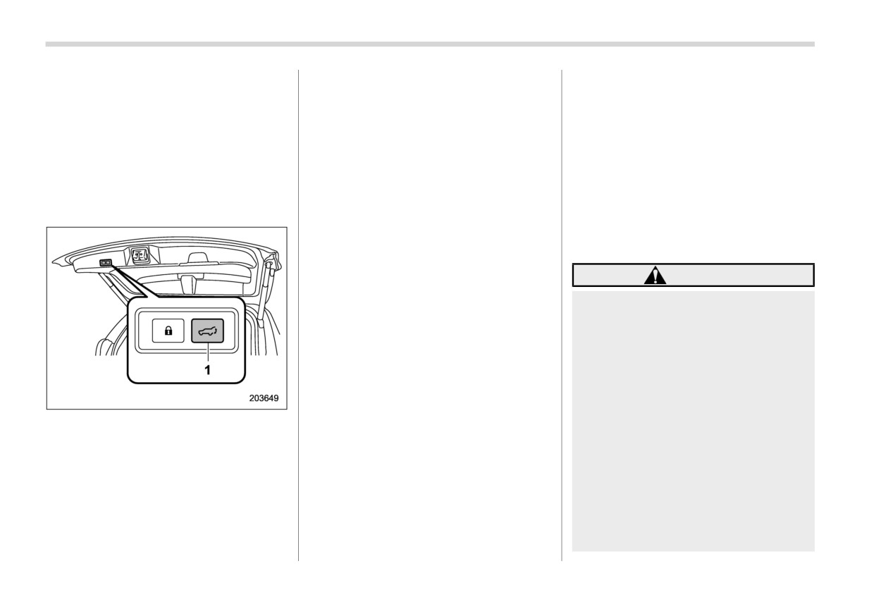
1
Power rear gate button
caught in the rear gate just before
- Register the position of the rear gate at
the fully open position.
it closes completely. Be careful
2.
Press and hold the power rear gate
not to catch your fingers and
button to register the height. An elec-
! Utilizing the memorized rear gate
other body parts.
tronic chirp sounds and the hazard
height
The reverse function may not
warning flashes for confirmation.
To open the rear gate and stop it at the
operate depending on the object
The rear gate will stop at the registered
shape and the manner in which it
registered height, perform the following
position when the memory function is on.
was caught. Be careful not to
procedure.
catch your fingers and other
Rear gate
155
body parts.
When closing the rear gate: The rear
! Rear gate auto closure function
gate will automatically open.
If, while fully opened via the power rear
gate function, the rear gate is lowered by
CAUTION
the weight of snow and such, an electronic
chirp will sound and the rear gate auto
If the reverse function is operated
closure function will apply braking to the
3 times consecutively, automatic
rear gate so that it prevents a rapid closure
opening and closing of the power
of the rear gate.
rear gate function will be can-
celed and the rear gate will stop
NOTE
opening or closing suddenly.
. If there is snow on the rear gate, only
However, the rear gate may open
use the power rear gate function
or close depending on the rear
after removing the snow.
gate height when automatic op-
. If you close the rear gate manually
eration is ceased. Be careful that
just after the rear gate is fully opened
the rear gate does not hit any-
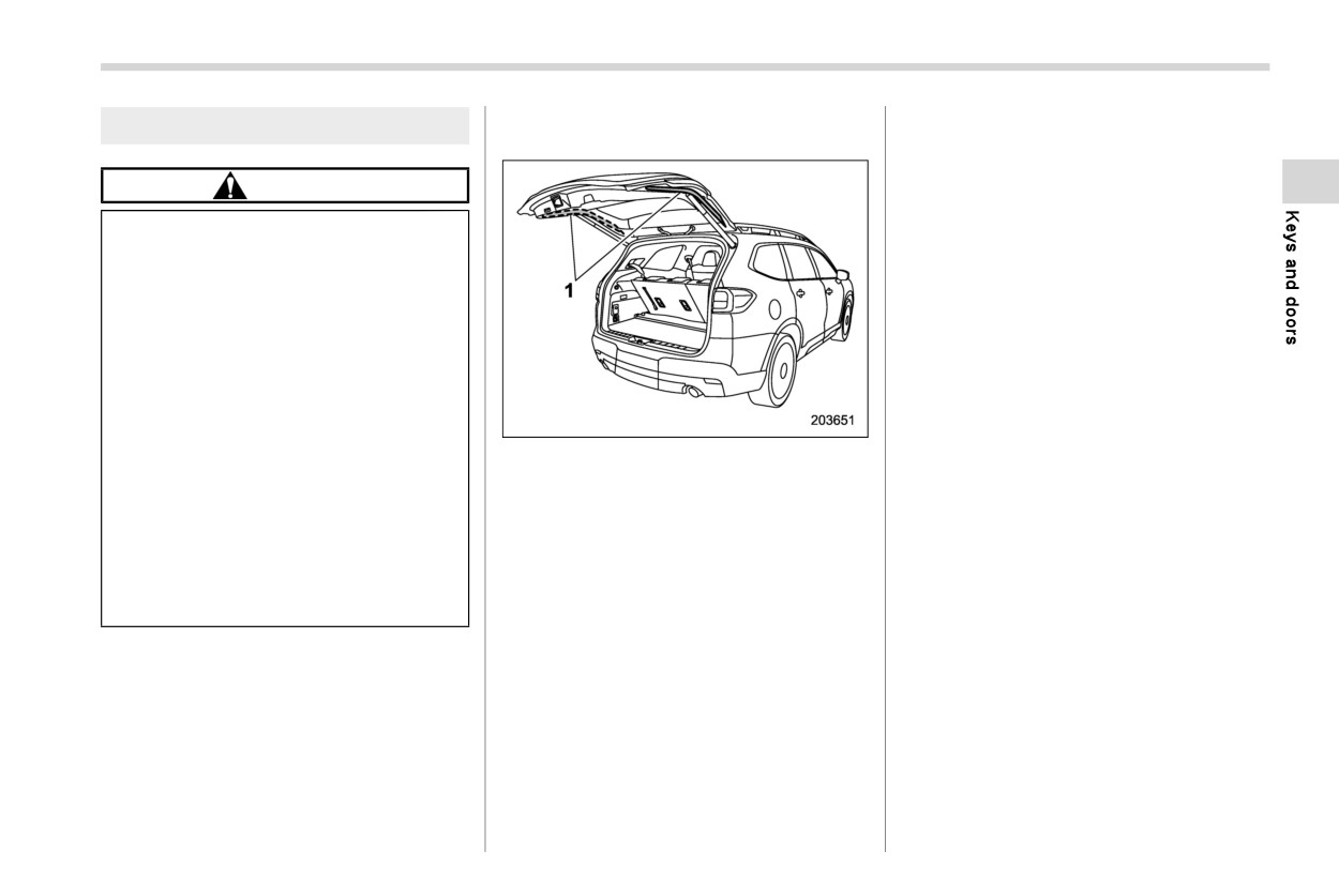
1
Touch sensors
using the power rear gate function,
one’s head or face, etc. and that
the rear gate drop prevention func-
fingers and baggage, etc. are not
Touch sensors are attached on the left and
tion will detect a rapid closure of the
caught in it.
right edges of the rear gate. If the touch
rear gate and apply braking to the
sensors detect fingers, baggage, etc.
Take care not to damage the
rear gate. In this case, this is not a
while closing by the power rear gate
touch sensors. Otherwise, the
function, an electronic chirp will sounds 3
malfunction.
reverse function may cease to
times and the rear gate will open auto-
operate.
! Selecting audible signal operation
matically.
Using an electronic chirp, the power rear
If, while opening or closing using power
NOTE
gate will give you an audible signal before
rear gate, the rear gate catches persons or
When the rear gate is opened using the
starting its operation. If desired, the audi-
baggage or hits an obstacle, an electronic
reverse function, it will be opened fully
ble signal can be turned off by a SUBARU
chirp will sound 3 times and the rear gate
dealer. Consult your SUBARU dealer for
or to the height registered in the
will operate as follows.
details.
memory function.
When opening the rear gate: The rear
For models with
“keyless access with
gate will automatically close.
push-button start system”, you can turn
the audible signal off by operating the
- CONTINUED -
156 Rear gate
center information display. For details,
! If the power rear gate is closed
and pull down the rear gate.
refer to “Car settings” FP215.
2. Operate the power rear gate and check
that the function operates properly.
The ON/OFF setting of the audible signal
also works as the audible signal settings
for the “remote keyless entry system” and
CAUTION
the “keyless access with push-button start
system”. However, for the warning chime
If the power rear gate function does
such as that caused by “Reverse function”
not operate properly, have your
FP154
or “Rear gate auto closure func-
vehicle checked by SUBARU dealer.
tion” FP155, it cannot be set as non-
operational.
! Initialization of power rear gate
If the power rear gate detects some
abnormality while operating, an electronic
chirp will sound and the power rear gate
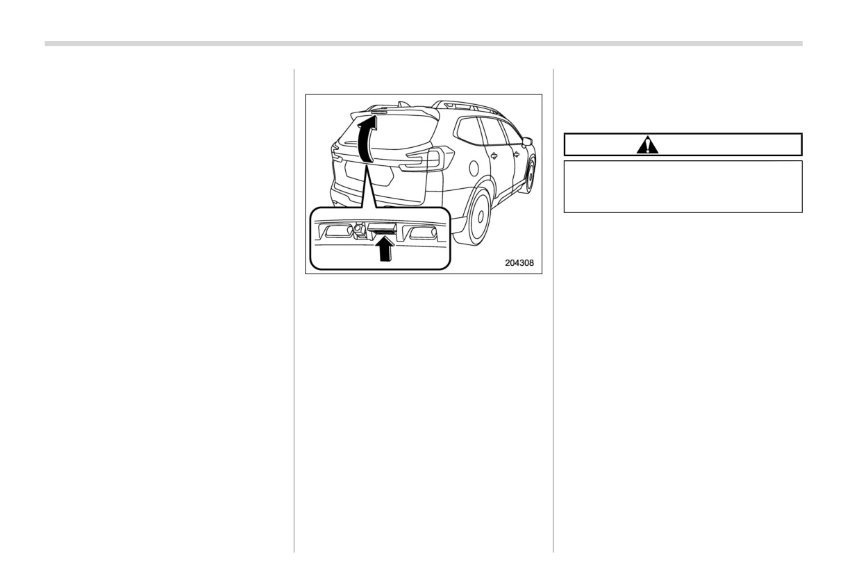
1.
Keep pressing the rear gate opener
operation will be automatically stopped in
switch until it unlocked (for approxi-
either opening or closing position. In this
mately 5 seconds) and lift up the rear
case, the system needs to be initialized in
gate.
the following order to restart the function
2.
Pull down the rear gate until it starts to
properly.
close automatically. The system will be
initialized once the gate is fully closed.
3.
Operate the power rear gate and check
that the function operates properly.
! If the power rear gate is opened
1.
Pull down the rear gate until it starts to
close automatically. The system will be
initialized once the gate is fully closed.
If the rear gate will not close comple-
tely, keep pressing the rear gate open-
er button for approximately 5 seconds
Moonroof
157
2-10. Moonroof (if equipped)
vehicle. Failure to follow this
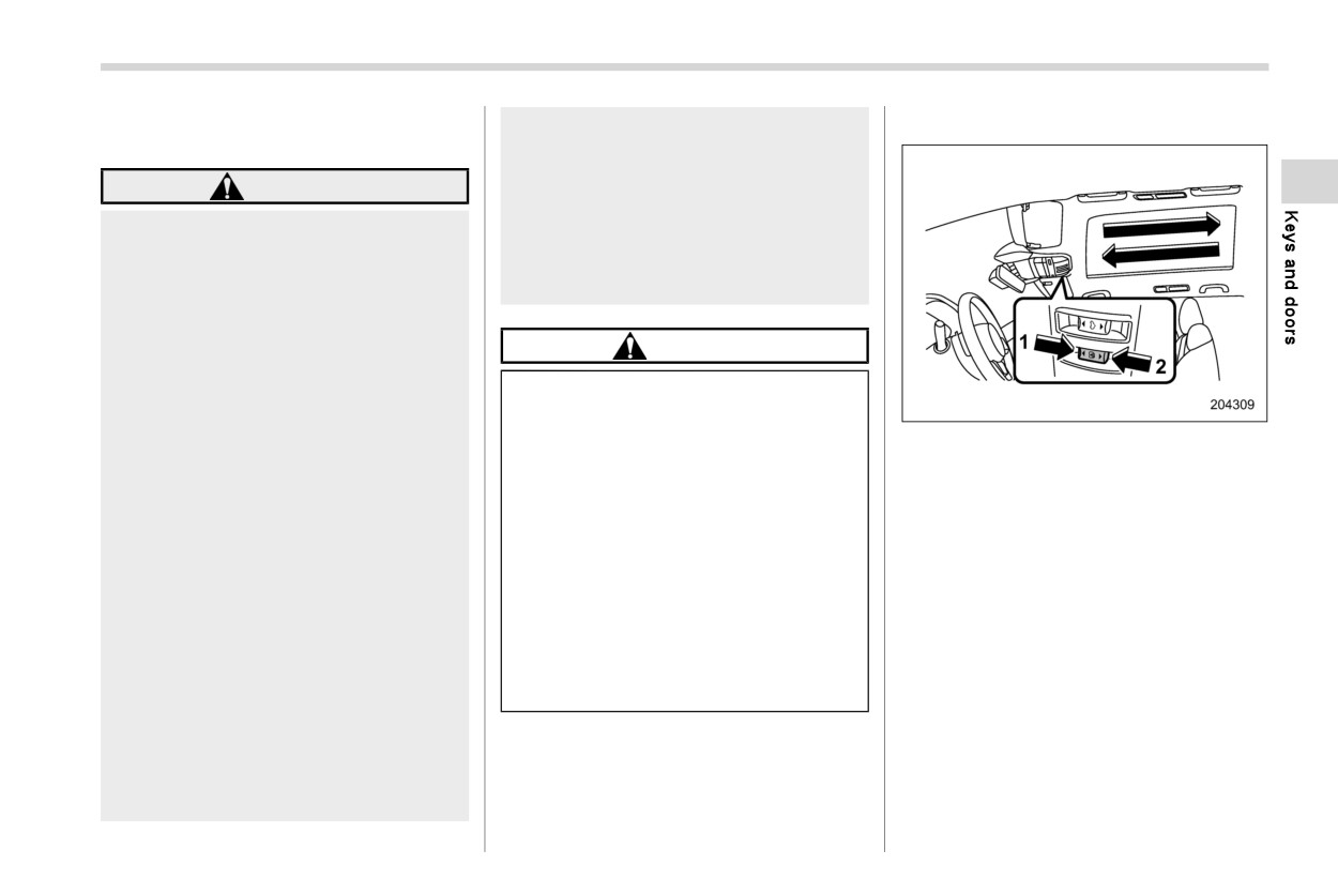
& Sunshade switch
procedure could result in injury
to a child operating the moon-
WARNING
roof.
Never try to check the anti-en-
Never let anyone’s hands, arms,
trapment function by deliberately
head or any objects protrude from
placing part of your body in the
the moonroof. A person could be
moonroof.
seriously injured if any of the follow-
ing conditions occur.
. The vehicle stops suddenly.
CAUTION
. The vehicle turns sharply.
Do not sit on the edge of the open
. The vehicle is involved in an
moonroof.
accident.
Do not operate the moonroof if
1
Open
. Body parts protruding from the
falling snow or extremely cold
2
Close
vehicle are struck by outside
conditions have caused it to
To open or close the sunshade using the
objects.
freeze shut.
automatic function, slide and
hold
the
To avoid serious personal injury
The anti-entrapment function
switch toward the open/close
side and
caused by entrapment, always con-
does not operate when the moon-
release.
form to the following instructions
roof is being tilted down. Be sure
To stop the sunshade halfway, slide the
without exception.
to confirm that it is safe to do so
sunshade switch either way.
before tilting the moonroof down.
. Before closing the moonroof,
make sure that no one’s hands,
If the moonroof does not close,
arms, head or other objects will
have the system checked by a
be accidentally caught in the
SUBARU dealer.
moonroof.
The moonroof has both tilting and sliding
. Always carry the key when you
functions.
leave the vehicle for safety rea-
sons and never allow an unat-
The moonroof operates only when the
tended child to remain in the
ignition switch is in the “ON” position.
- CONTINUED -
158 Moonroof
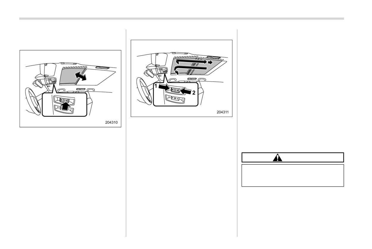
& Moonroof switch
! Sliding moonroof
NOTE
. After washing the vehicle or after it
! Tilting moonroof
rains, wipe away water on the roof
prior to opening the moonroof to
prevent drops of water from falling
into the passenger compartment.
. For the sake of safety, it is recom-
mended that you avoid driving with
the moonroof fully opened.
! Anti-entrapment function
When the moonroof senses a substantial
enough object trapped between its glass
and the vehicle’s roof during closure, it
1
Open
automatically moves back to the fully open
2
Close
position and stops there. The anti-entrap-
To raise or lower the moonroof, press the
ment function may also be activated by a
To open the moonroof:
moonroof switch.
strong shock on the moonroof even when
When the moonroof switch is slided and
If the shade is closed past the half-open
there is nothing trapped.
held to the open side, the moonroof will
position when the switch is pressed, it will
open, then stop slightly before the fully
open up to the half-open position.
CAUTION
open position to reduce wind noise.
NOTE
Slide the moonroof switch again to fully
Never attempt to test this function
Release the switch after the moonroof
open the moonroof.
using fingers, hands or other parts
has been raised or has been lowered
To close the moonroof:
of your body.
completely. Pressing the switch con-
When the moonroof switch is slided and
tinuously may cause damage to the
held to the close side, the moonroof will
moonroof.
close, then stop at the tilt-up position.
Slide and hold the moonroof switch again
to fully close the moonroof.
To stop the moonroof halfway, slide the
moonroof switch either way.
Rear door window sunshades
159
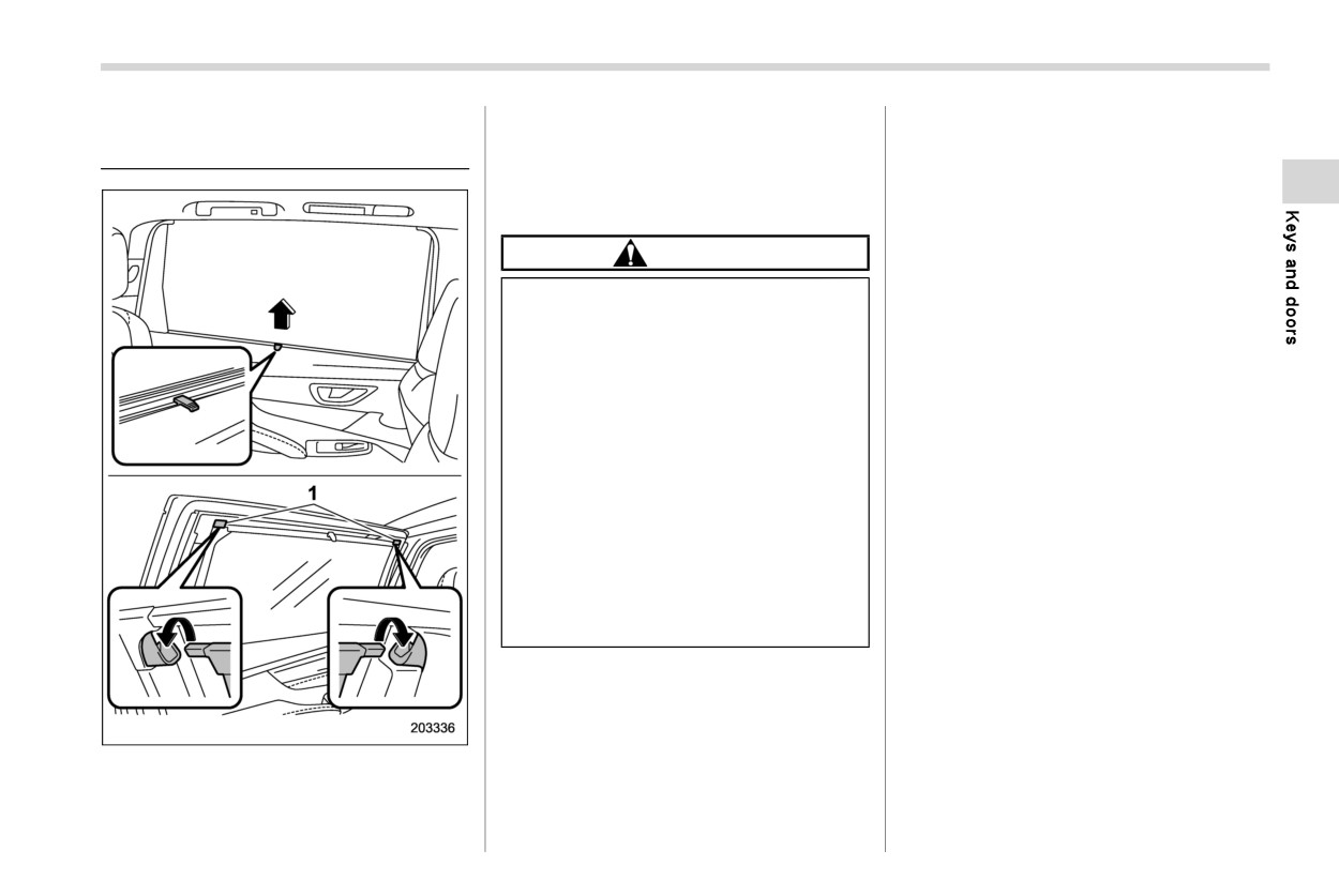
To use the sunshade, pull it up and hang it
2-11. Rear door window sun-
on the hooks.
shades (if equipped)
To retract the sunshade, release it from the
hooks slowly and allow it to roll into the
door trim.
CAUTION
Do not use the rear door window
sunshade when the window is
opened. There is a risk that the
rear door window sunshade will
come off of the hook.
To ensure normal operation of the
sunshades, observe the follow-
ing precautions.
- Do not put anything where it
may hinder the opening/clos-
ing of a sunshade.
- Do not put anything on the
sunshades.
- Do not hang anything on the
hook.
1
Hook
The rear door window sunshades are built
in the rear door trim.
Instruments and controls
CHECK ENGINE warning light/Malfunction
3-1. Ignition switch (models without “keyless
indicator light
176
access with push-button start system”)
164
Charge warning light
177
Key positions
164
Oil pressure warning light
177
Key reminder chime
165
Engine low oil level warning light
177
Ignition switch light (if equipped)
165
Windshield washer fluid warning light
178
3
3-2. Push-button ignition switch (models with
AT OIL TEMP warning light
178
“keyless access with push-button start
Rear differential oil temperature warning light
system”)
166
(if equipped)
178
Safety precautions
166
Low tire pressure warning light (U.S.-spec.
Operating range for push-button start system
166
models)
179
Switching power status
167
ABS warning light
180
When access key fob does not operate
Brake system warning light
181
properly
168
Electronic parking brake indicator light
181
3-3. Hazard warning flasher
168
Auto Vehicle Hold indicator light
183
3-4. Meters and gauges
168
Low fuel warning light
183
Speedometer
168
Door open warning light
183
Tachometer
168
Engine hood open warning light
183
Odometer
169
All-Wheel Drive warning light
183
Double trip meter
169
Power steering warning light
184
Fuel gauge
170
Vehicle Dynamics Control warning light/Vehicle
Engine coolant temperature gauge
170
Dynamics Control operation indicator light
184
ECO gauge
171
Vehicle Dynamics Control OFF indicator light
185
Combination meter settings
171
Warning chimes and warning indicator of
3-5. Illumination brightness control
171
the keyless access with push-button start
system (if equipped)
186
Auto dimmer cancel function
172
Security indicator light
190
3-6. Warning and indicator lights
172
Select lever/gear position indicator
191
Initial illumination for system check
172
Turn signal indicator lights
191
Seatbelt warning light and chime
173
High beam indicator light
191
SRS airbag system warning light
175
High beam assist indicator light
191
Front passenger’s frontal airbag ON and OFF
indicator lights
176
Instruments and controls
Automatic headlight beam leveler warning
Telltale screen
197
light
191
Basic screens
198
LED headlight warning light
191
3-8. Center information display (CID)
201
Steering Responsive Headlight OFF indicator
Features
201
light
191
Welcome screen
202
Steering Responsive Headlight warning light
192
Good-bye screen
202
Front fog light indicator light (if equipped)
192
Interruption screen
202
Headlight indicator light
192
Touch screen operations
202
X-MODE indicator
192
Display
203
Hill descent control indicator
192
3-9. Clock
228
BSD/RCTA warning indicator (if equipped)
192
Setting the clock manually
228
BSD/RCTA OFF indicator (if equipped)
192
Setting the clock automatically
228
RAB warning indicator (if equipped)
193
Time Zone (models with navigation system)
229
RAB OFF indicator (if equipped)
193
Daylight Saving Time (models with navigation
Icy road surface warning indicator
193
system)
229
Driver Monitoring System operation indicator
3-10. Valet Mode
230
light (green) (if equipped)
193
Activation of Valet Mode
230
Driver Monitoring System warning light (yellow)
Deactivation of Valet Mode
230
(if equipped)
193
Driver Monitoring System OFF indicator light
3-11. Light control switch
231
(if equipped)
193
Precautions and tips
231
Driver Monitoring System temporary stop
Headlights
231
indicator light (if equipped)
193
High/low beam change (dimmer)
234
One-touch Interior Illumination indicator
Headlight flasher
234
(if equipped)
194
High beam assist function
234
3-7. Combination meter display (color LCD)
194
Daytime running light system
237
Basic operation
195
3-12. Steering Responsive Headlight (SRH)
238
Welcome screen (opening animation) and
3-13. Headlight beam leveler
239
Good-bye screen (ending animation)
195
3-14. Fog light switch (if equipped)
239
Warning screen
196
3-15. Turn signal lever
240
Meter information screen
196
One-touch lane changer
240
Instruments and controls
3-16. Wiper and washer
241
Smart Rearview Mirror/compass with HomeLink
®
(if equipped)
254
Windshield wiper and washer switches
243
Rear window wiper and washer switch
245
Outside mirrors
269
3-17. Mirrors
246
3-18. Defogger and deicer
273
Inside mirror (if equipped)
246
3-19. Tilt/telescopic steering wheel
274
Auto-dimming mirror/compass with HomeLink®
Heated Steering Wheel system (if equipped)
275
(if equipped)
247
3-20. Horn
276
164 Ignition switch (models without “keyless access with push-button start system”)
3-1. Ignition switch (models
CAUTION
NOTE
without “keyless access with
. Keep the ignition switch in the
Do not attach a large key holder or
“LOCK” position when the engine
push-button start system”)
key case to either key. If it banged
is not running.
against your knees or hands while
. Using electrical accessories for a
you are driving, it could turn the
WARNING
long time with the ignition switch in
ignition switch from the “ON” posi-
the
“ON” or “ACC” position can
Never turn the ignition switch to
tion to the “ACC” or “LOCK” posi-
cause the battery to go dead.
the “LOCK” position while the
tion, thereby stopping the engine.
. If the ignition switch will not move
vehicle is being driven or towed
Also, if the key is attached to a key
from the “LOCK” position to the
because that will lock the steer-
holder or to a large bunch of other
“ACC” position, turn the steering
ing wheel, preventing steering
keys, centrifugal force may act on it
wheel slightly to the left and right as
control. And when the engine is
as the vehicle moves, resulting in
you turn the ignition switch.
turned off, it takes a much greater
unwanted
turning
of
the
ignition
effort than usual to steer.
switch.
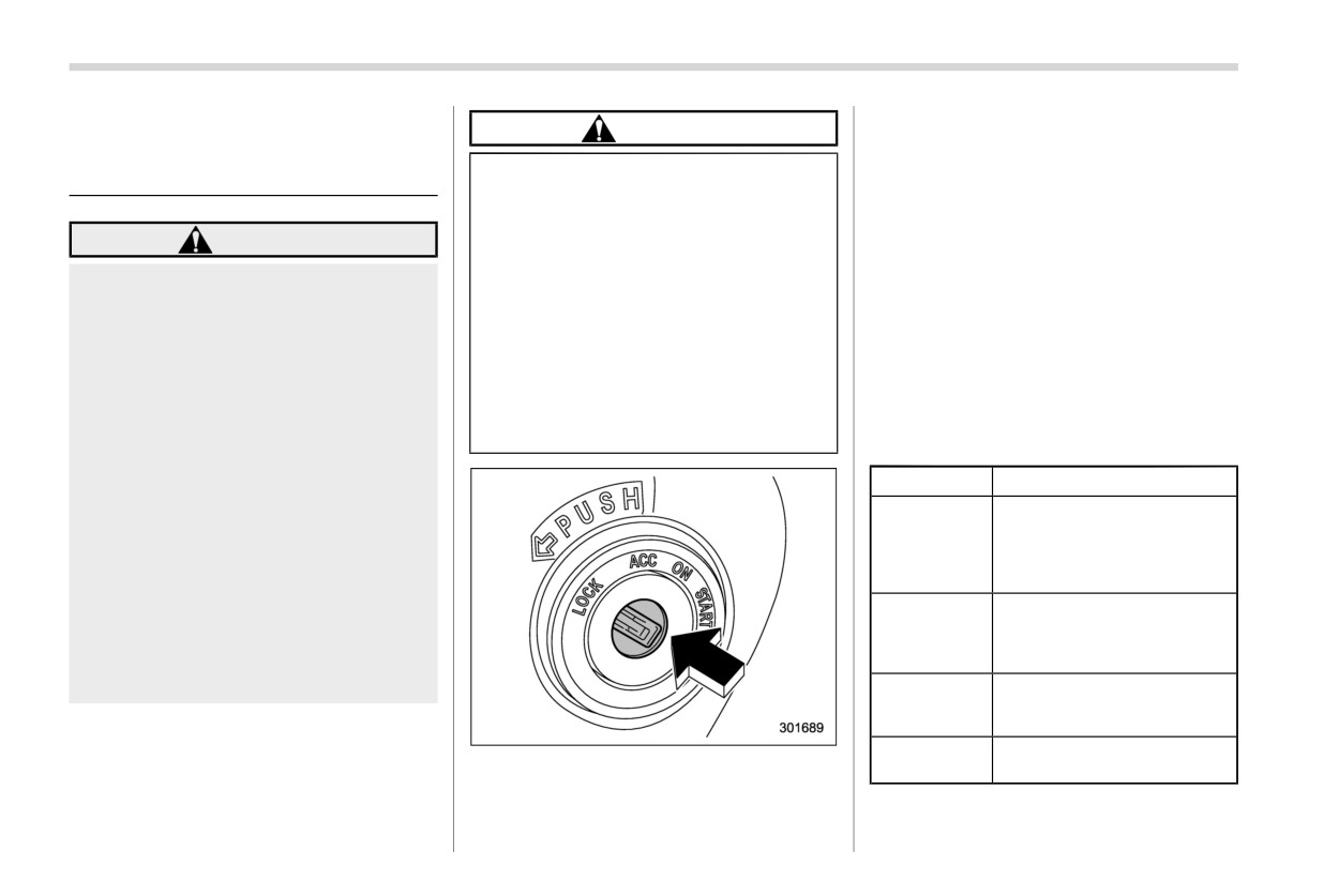
& Key positions
Before leaving the vehicle, al-
ways remove the key from the
Position
Description
ignition switch for safety and
The key can only be inserted
never allow an unattended child
or removed in this position.
LOCK
The ignition switch will lock
to remain in the vehicle. Failure to
the steering wheel when you
follow this procedure could re-
remove the key.
sult in injury to a child or others.
In this position the electrical
Children could operate the power
accessories (audio, acces-
ACC
windows, the moonroof or other
sory power outlet, etc.) can be
controls or even make the vehicle
used.
move.
This is the normal operating
ON
position after starting the en-
gine.
The engine is started in this
START
The ignition
switch
has
four
positions:
position.
LOCK, ACC, ON and START.
Ignition switch (models without “keyless access with push-button start system”)
165
The engine may not start in the
ponder.
CAUTION
following cases:
- The key is near or touching
Do not turn the ignition switch to the
another transmitter.
“START” position while the engine
is running.
& Key reminder chime
The reminder chime sounds when the
driver’s door is opened and the ignition
switch is in the “LOCK” or “ACC” position.
The chime stops under the following
conditions.
. The ignition switch is turned to the “ON”
position.
. The key is removed from the ignition
switch.
-
The key grip is touching another
. The driver’s door is closed.
key or a metallic key holder.
& Ignition switch light (if
equipped)
NOTE
. To turn the key from the “ACC” to
For easy access to the ignition switch in
“LOCK” position, the select lever
the dark, the ignition switch light illumi-
must be in the “P” position and the
nates when the driver’s door is opened or
key must be pushed in and turned.
when the driver’s door is unlocked using
. If your registered key fails to start
the remote keyless entry transmitter.
the engine, pull out the key once (the
The light remains illuminated for several
security indicator light will blink),
tens of seconds and then gradually turns
and then insert the key again and
off under the following conditions.
turn it to the “START” position again
. The driver’s door is closed.
to restart the engine.
. The doors are unlocked using the
-
The key is near another key that
remote keyless entry transmitter.
contains an immobilizer trans-
- CONTINUED -
166 Push-button ignition switch (models with “keyless access with push-button start system”)
The light turns off immediately under the
engine start cannot be operated.
3-2. Push-button ignition
following conditions.
Even when the access key fob is
switch (models with “keyless
The ignition switch is turned to the “ON”
outside the vehicle, if it is placed too
access with push-button start
position.
close to the glass, it may be possible
system”)
to switch the power or to start the
All doors and the rear gate are locked
using the remote keyless entry trans-
engine.
& Safety precautions
Do not leave the access key fob in
mitter.
Refer to “Safety precautions” FP1 18.
the following places. It may become
impossible to operate the push-
& Operating range for push-
button ignition switch and the en-
gine start. It may also cause a false
button start system
warning to issue although no mal-
function actually occurs, or not to
issue a warning when any malfunc-
tion occurs.
- On the instrument panel
- On the floor
- Inside the glove box
- Inside the door trim pocket
- On the rear seat
- In the cargo area
When operating the push-button
ignition switch or starting the en-
gine, if the access key fob battery is
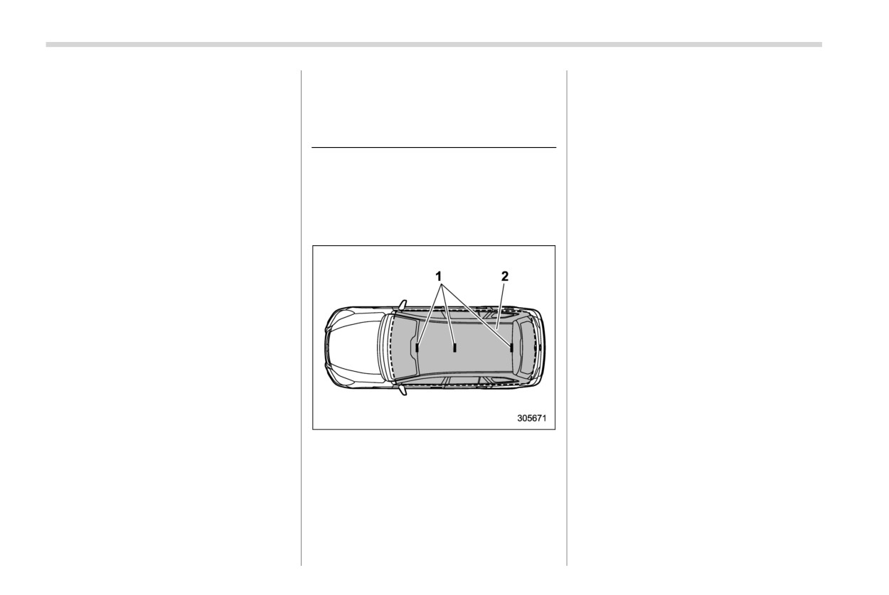
1
Antennas
discharged, perform the procedure
2
Operating range
described in “Access key fob - if
access key fob does not operate
properly” FP464. In such a case,
NOTE
replace the battery immediately. Re-
. If the access key fob is not detected
fer to “Replacing battery of access
within the operating range of the
key fob” FP517.
antennas inside the vehicle, the
push-button ignition switch and the
Push-button ignition switch (models with “keyless access with push-button start system”)
167
& Switching power status
in orange.
may cause a malfunction.
If the push-button ignition switch
Power
Indicator color
Operation
does not operate smoothly, stop
status
the operation. Contact a SUBARU
Power is turned
OFF
Turned off
dealer immediately.
off.
If the push-button ignition switch
The following
systems can be
does not illuminate even when
used:
the instrument panel illumination
ACC
Orange
audio and ac-
is turned on, have the vehicle
cessory power
outlet.
inspected at a SUBARU dealer.
If the vehicle was left in the hot
Orange
(while engine is
sun for a long time, the surface of
stopped)
All electrical
the push-button ignition switch
ON
systems can be
Turned off
may get hot. Be careful not to
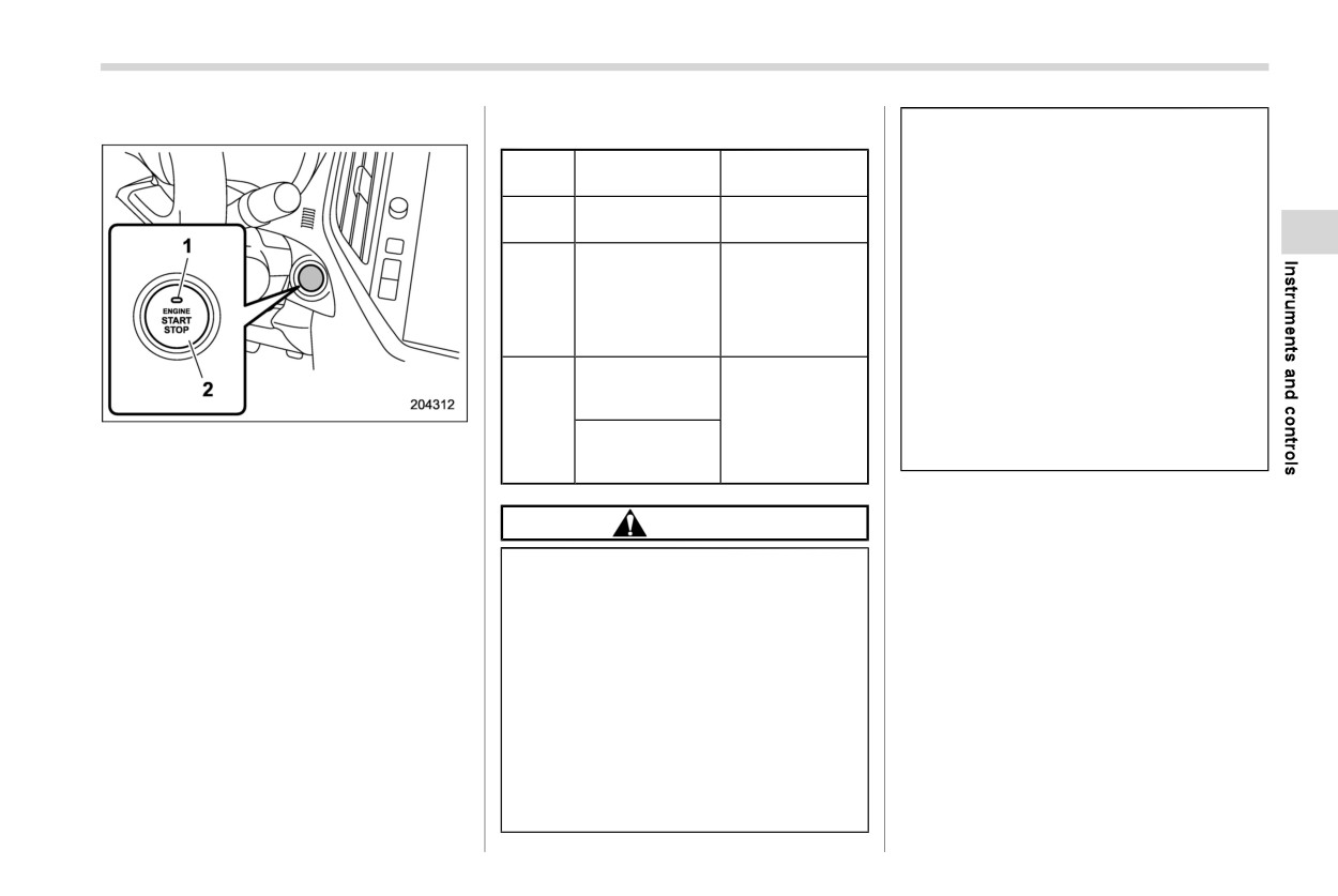
1
Operation indicator
used.
(while engine is
burn yourself.
2
Push-button ignition switch
running)
The
power is switched every
time
the
NOTE
push-button ignition switch is pressed.
CAUTION
. When operating the push-button
1. Carry the access key fob, and sit in the
When the push-button ignition
ignition switch, firmly press it all
driver’s seat.
switch is left in “ON” (while the
the way.
2. Shift the select lever into the “P”/“N”
engine is not running) or “ACC”
. If the push-button ignition switch is
position.
for a long time, it may result in
pressed quickly, the power may not
3. Press the push-button ignition switch
vehicle battery discharge.
turn on or off.
without depressing the brake pedal.
. If the indicator light on the push-
Every time the button is pressed, the
Do not spill drinks or other liquids
button ignition switch flashes in
power is switched in the sequence of
on the push-button ignition
green when the push-button ignition
“OFF”, “ACC”, “ON” and “OFF”. When
switch. It may cause a malfunc-
switch is pressed, steering is
the engine is stopped and the push-
tion.
locked. When this occurs, press the
button ignition switch is in “ACC” or
Do not touch the push-button
push-button ignition switch while
“ON”, the operation indicator on the
ignition switch with a hand soiled
turning the steering wheel left and
push-button ignition switch illuminates
with oil or other contaminants. It
right.
- CONTINUED -
168 Hazard warning flasher
3-3. Hazard warning flasher
3-4. Meters and gauges
! Battery drainage prevention func-
tion
NOTE
When the push-button ignition switch is left
in the “ACC” or “ON” position for approxi-
Some of the meters and gauges on the
mately 1 hour, the push-button ignition
combination meter use liquid-crystal
switch will be automatically switched to
displays. You will find their indications
“OFF” to prevent the battery from going
hard to see if you wear polarized
dead.
glasses.
& When access key fob does
& Speedometer
not operate properly
The speedometer shows the vehicle
Refer to “Access key fob - if access key
speed.
fob does not operate properly” FP464.
& Tachometer
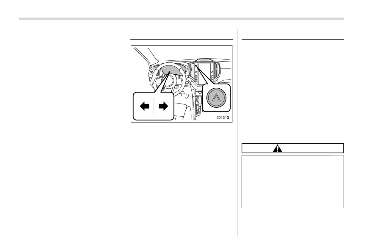
The hazard warning flasher is used to warn
The tachometer shows the engine speed
other drivers when you have to park your
in thousands of revolutions per minute.
vehicle under emergency conditions. The
hazard warning flasher works regardless
CAUTION
of the position of the ignition switch.
Do not operate the engine with the
To turn on the hazard warning flasher,
pointer of the tachometer in the red
push the hazard warning flasher switch on
zone. In this range, fuel injection will
the instrument panel. All the turn signal
be cut by the engine control module
lights and the turn signal indicator lights
will flash. To turn off the flasher, push the
to protect the engine from overrev-
ving. The engine will resume run-
switch again.
ning normally after the engine speed
NOTE
is reduced below the red zone.
When the hazard warning flasher is on,
the turn signals do not work.
Meters and gauges
169
& Odometer
& Double trip meter
To reset the trip meter, select either the A
trip or B trip meter, then press and hold the
TRIP RESET switch.
CAUTION
To ensure safety, do not attempt to
change the function of the indicator
during driving, as an accident could
result.
NOTE
If the connection between the com-
bination meter and battery is broken
1
TRIP RESET switch
1
TRIP RESET switch
for any reason such as vehicle
2
Combination meter
2
Combination meter
maintenance or fuse replacement,
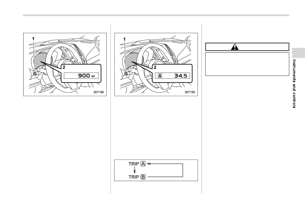
This meter displays the odometer when
This meter displays the two trip meters
the data recorded on the trip meter
the ignition switch is in the “ON” position.
when the ignition switch is in the “ON”
will be lost.
position.
If you press the TRIP RESET switch
The odometer shows the total distance
when the ignition switch is in the
that the vehicle has been driven.
The trip meter shows the distance that the
“LOCK”/“OFF” or “ACC” position,
vehicle has been driven since you last set
NOTE
the odometer/trip meter will light up.
it to zero.
It is possible to switch between the A
If you press the TRIP RESET switch
The display can be switched as shown in
trip meter and B trip meter indica-
when the ignition switch is in the
the following sequence by pressing the
tions while the odometer/trip meter
“LOCK”/“OFF” or “ACC” position, the
TRIP RESET switch.
is lit up.
odometer/trip meter will light up.
In addition, it is possible to reset the
The indicators will turn off when:
trip meter by pressing and holding
. The TRIP RESET switch is not oper-
the TRIP RESET switch.
ated for approximately 10 seconds.
The indicators will turn off when:
. The driver’s door is opened and then
- The TRIP RESET switch is not
closed.
operated for approximately 10
- CONTINUED -
170 Meters and gauges
seconds.
filler lid is located on the right side of
The engine coolant temperature will vary
– The driver’s door is opened and
the vehicle.
in accordance with the outside tempera-
then closed.
. If you press the TRIP RESET switch
ture and driving conditions.
while the ignition switch is in the
We recommend that you drive moderately
“LOCK”/“OFF” or “ACC” position,
& Fuel gauge
until the pointer of the engine coolant
the fuel gauge will light up and
temperature gauge reaches near the mid-
indicate the amount of fuel remain-
dle of the range. Engine operation is
ing in the tank.
optimum with the engine coolant at this
The gauge will turn off when the
temperature range and high revving op-
TRIP RESET switch is not operated
eration when the engine is not warmed up
for approximately 10 seconds.
enough should be avoided.
& Engine coolant temperature
CAUTION
gauge
If the pointer exceeds the normal
operating range, safely stop the
vehicle as soon as possible.
Refer to
“Engine overheating”
FP459.
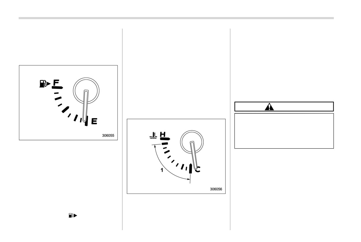
The fuel
gauge shows the approximate
amount of fuel remaining in the tank.
When the ignition switch is in the “LOCK”/
“OFF” or “ACC” position, the fuel gauge
shows “E” even if the fuel tank contains
fuel.
The gauge may move slightly due to fuel
level movement in the tank (e.g., during
braking, turning or acceleration).
1
Normal operating range
NOTE
The engine coolant temperature gauge
shows engine coolant temperature when
. You will see the “
” sign in the fuel
the ignition switch is in the “ON” position.
gauge. This indicates that the fuel
Illumination brightness control
171
& ECO gauge
& Combination meter settings
3-5. Illumination brightness
Meter settings can be set on the center
control
information display. For details, perform
the procedures described in
“General
settings” FP210.
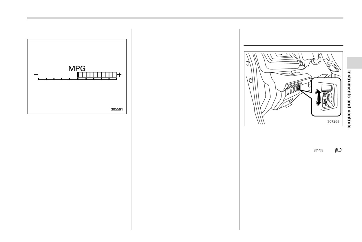
The ECO gauge shows the difference
between the current rate of fuel consump-
tion and the average rate of fuel consump-
The illumination brightness of the combi-
tion since the trip meter was last reset.
nation meter and center information dis-
play dims under the following conditions.
If the ECO gauge moves towards the right
. The light switch is in the “
” or “
”
side, this indicates better fuel efficiency.
position when the ambient light is dark.
NOTE
. The light control switch is in the “AUTO”
position and the headlights illuminate
. The ECO gauge shows only an
approximate indication of fuel effi-
automatically.
ciency.
You can adjust the illumination brightness
. After resetting the trip meter, the
for better visibility.
average rate of fuel consumption is
not shown until you have driven for 1
To brighten, turn the control dial upward.
mile (or 1 km). Before that time, the
To darken, turn the control dial downward.
ECO gauge does not operate.
- CONTINUED -
172 Warning and indicator lights
NOTE
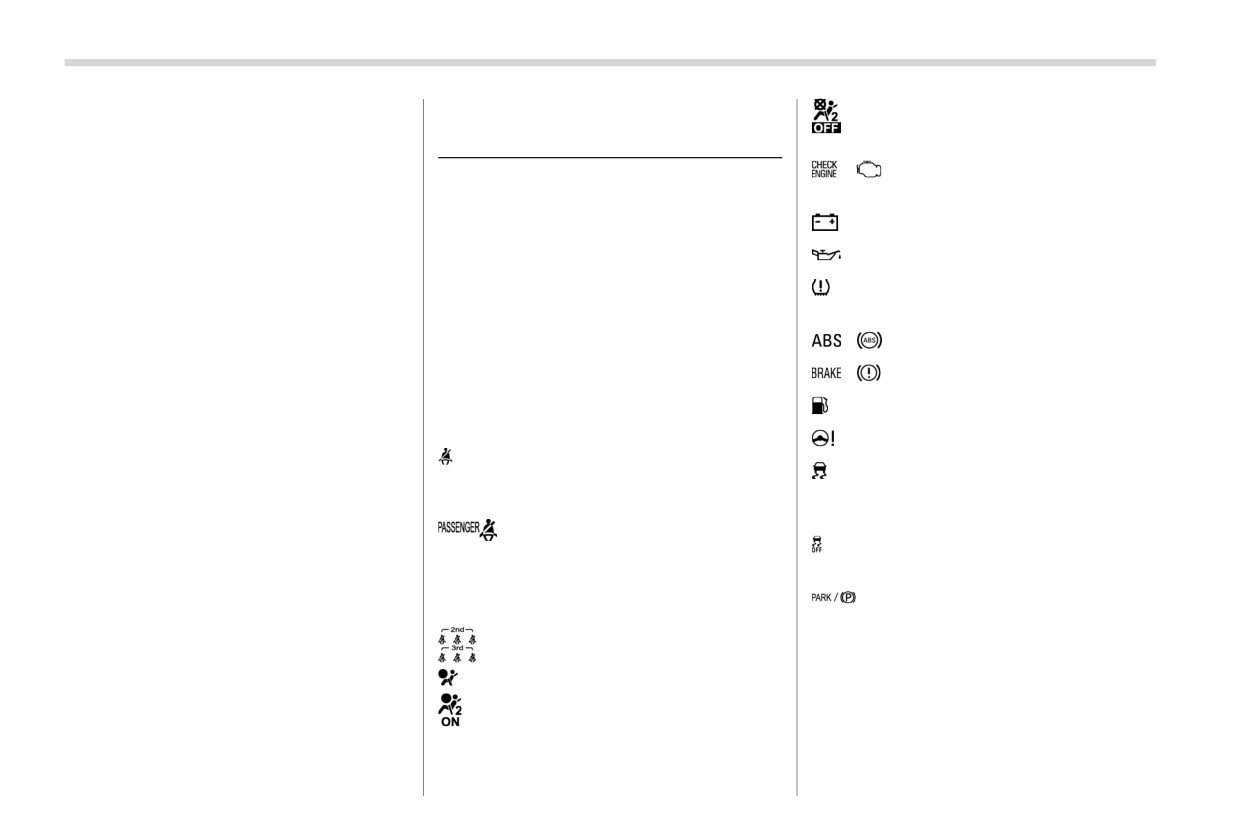
3-6. Warning and indicator
: Front passenger’s frontal airbag OFF
indicator light
. When the control dial is turned fully
lights
upward, the illumination brightness
/
: CHECK ENGINE warning light/
becomes the maximum and the
& Initial illumination for system
Malfunction indicator light
automatic dimming function does
check
: Charge warning light
not work at all.
Several of the warning and indicator lights
. The brightness setting is not can-
illuminate momentarily and then go out
: Oil pressure warning light
celed even when the ignition switch
when the ignition switch is initially turned to
is turned to the “LOCK”/“OFF” posi-
: Low tire pressure warning light (U.S.-
the “ON” position. This permits checking
tion.
spec. models)
the operation of the bulbs.
/
: ABS warning light
Apply the parking brake and turn the
& Auto dimmer cancel function
ignition switch to the “ON” position. For
/
: Brake system warning light
When the ambient light is bright, the
the system check, the following lights
illumination brightness is set to the max-
: Low fuel warning light
illuminate and turn off after several sec-
imum regardless of the position of the
onds or after the engine has started.
: Power steering warning light
control dial. In this case, you cannot adjust
: Seatbelt warning light
(The seatbelt
the illumination brightness by using the
: Vehicle Dynamics Control warning light/
warning light turns off only when the
control dial. When the ambient light is dark,
Vehicle Dynamics Control operation
driver fastens the seatbelt.)
you can dim the illumination brightness as
indicator light
described above.
: Front passenger’s seatbelt warn-
: Vehicle Dynamics Control OFF indicator
ing light
(The seatbelt warning
The operational/non-operational setting
light
light turns off only when the front
and sensitivity of the auto dimmer cancel
seat passenger fastens the seat-
: Electronic parking brake indicator
function can be changed by your SUBARU
belt.)
dealer. Contact your SUBARU dealer for
light
details.
: Rear seatbelt warning light
If any lights fail to illuminate, it indicates a
burned-out bulb or a malfunction of the
: SRS airbag system warning light
corresponding system.
: Front passenger’s frontal airbag ON
Consult your authorized SUBARU dealer
indicator light
for repair.
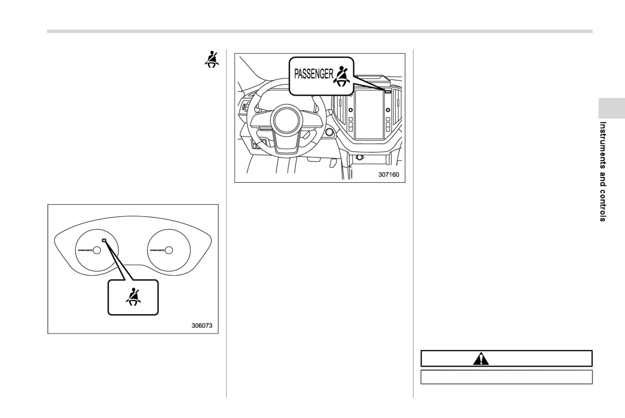
Warning and indicator lights
173
& Seatbelt warning light
–
The warning light will blink, and
the warning chime will make a
and chime
peep sound when driving be-
Your vehicle is equipped with a seatbelt
tween approximately 4 mph (6
warning device at the driver’s and passen-
km/h) and 13 mph (20 km/h). The
ger’s seats, as required by current safety
warning chime will stop when the
standards.
vehicle stops.
-
The warning light will blink, and
! Driver’s and front passenger’s seats
the warning chime will sound
With the ignition switch turned to the “ON”
loudly when 15 seconds have
position, this device reminds the driver and
elapsed while driving between
front passenger to fasten their seatbelts by
approximately 4 mph (6 km/h)
illuminating the warning lights in the loca-
and 13 mph (20 km/h).
tions indicated in the following illustration
Front passenger’s seat
-
The warning light will blink, and
and sounding a chime.
the warning chime will sound
! Operation
loudly when driving approxi-
When the ignition switch is turned to the
mately more than 13 mph (20
“ON” position, the driver’s and/or front
km/h).
passenger’s warning light will illuminate,
The warning light will turn off and the
then it will blink for several seconds. If the
warning chime will stop when the
seatbelt of the driver’s seat is not fastened,
seatbelt is fastened.
the warning chime may make a peep
If
there is no passenger on the front
sound.
passenger’s seat, the seatbelt warning
NOTE
system for the front passenger’s seat will
be deactivated. The front passenger’s
. If the driver’s and/or front passen-
seatbelt warning system monitors whether
ger’s seatbelt(s) are/is not fastened
or not there is a passenger on the front
while driving, the seatbelt warning
Driver’s seat
passenger’s seat.
system operates as follows accord-
ing to the vehicle speed.
CAUTION
- The warning light will illuminate
when driving approximately 4
Observe the following precautions.
mph (6 km/h) or less.
- CONTINUED -
174 Warning and indicator lights
Failure to do so may prevent the
strongly recommend that all children sit
! Rear passenger’s seats
device from functioning correctly or
in the rear seat properly restrained.
cause the device to fail.
. Ensure that there is no article left in the
seatback pocket.
Do not install any accessory such
as a table or TV onto the seat-
. Ensure that the backward-forward po-
back.
sition and seatback of front passen-
ger’s seat are locked into place se-
Do not store a heavy load in the
curely by moving the seat back and
seatback pocket.
forth.
Do not allow the rear seat occu-
pant to place his/her hands or
If still the seatbelt warning system for front
legs on the front passenger’s
passenger’s seat does not function cor-
seatback, or allow him/her to pull
rectly after taking relevant corrective ac-
the seatback.
tions described above, immediately con-
tact your SUBARU dealer for an inspec-
Do not use front seats with their
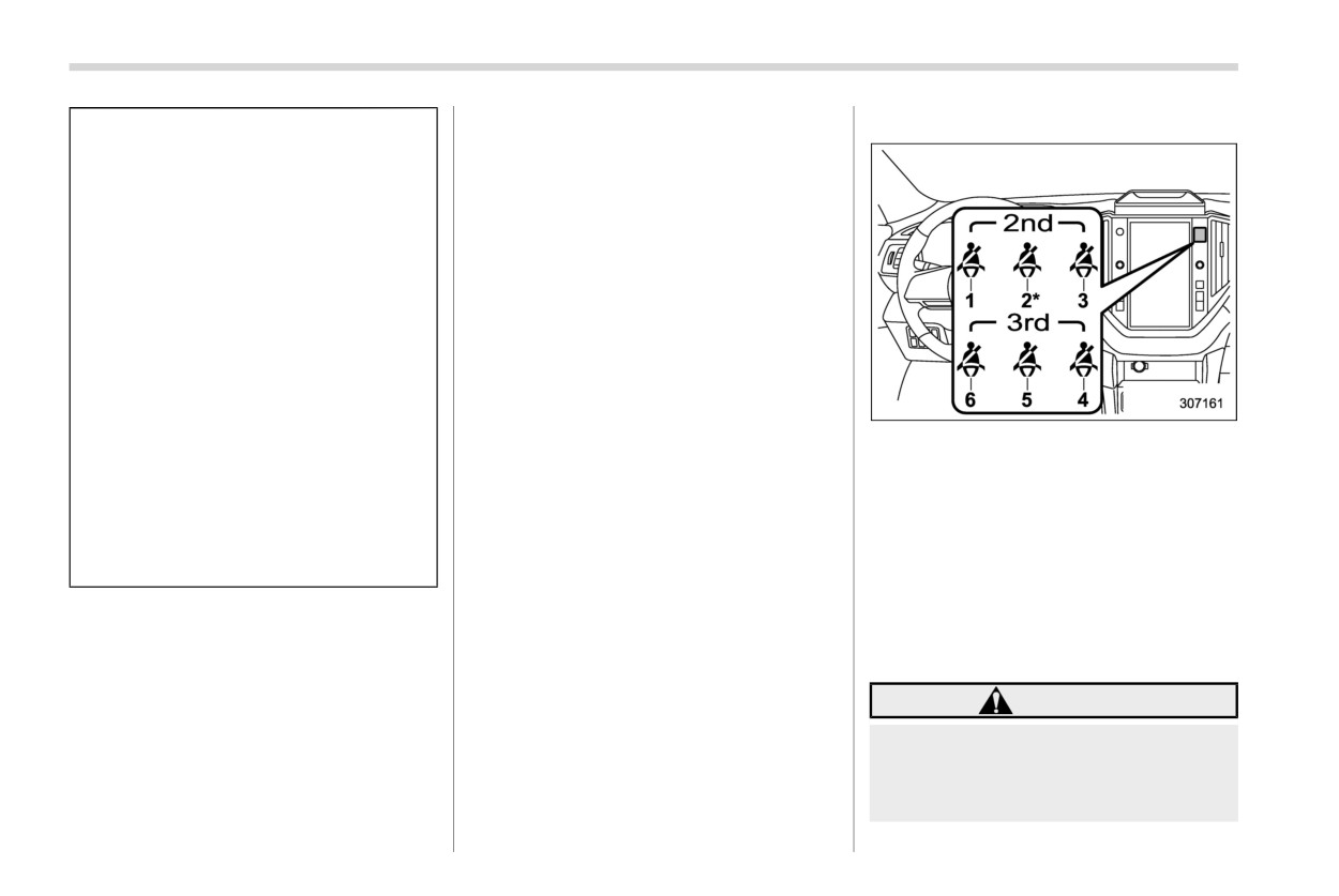
1
Second-row left seat
tion.
backward-forward position and
2
Second-row center seat*
seatback not being locked into
3
Second-row right seat
place securely. If any of them are
4
Third-row right seat
not locked securely, adjust them
5
Third-row center seat
again. For adjusting procedure,
6
Third-row left seat
refer to “Manual seat” FP33.
*: Second-row bench seat models
The layout of those warning lights is shown
If the seatbelt warning system for the front
in the illustration. When the seatbelts are
passenger’s seat does not function cor-
not fastened, the warning lights for the
rectly (e.g., it is activated even when the
seats will illuminate or blink.
front passenger’s seat is empty or it is
deactivated even when the front passen-
WARNING
ger has not fastened his/her seatbelt), take
the following actions.
. The driver must check that the all
. Ensure that no article is placed on the
passengers have fastened their
seat other than a child restraint system
seatbelts properly since the seat-
and its child occupant, although we
belt warning system may not
Warning and indicator lights
175
detect passengers under the fol-
chime.
and a warning chime will sound.
lowing circumstances.
. When folding second- or third-row
The chime will make a peep
seats, ensure that the seats are
sound for 15 seconds, and it then
- When cushions or child re-
empty prior to folding. Items caught
will become louder and continue
straint systems, etc., are used
between the seat bottom and seat-
for 35 seconds. The warning light
- When a child or small adult is
back, when folded, may damage the
will blink for 50 seconds, then it
sitting in the seat
seat surface or activate the passen-
will illuminate steadily and the
Observe the following precau-
ger seatbelt warning light and
chime will stop.
tions
chime.
-
When driving more than approxi-
- Do not apply any strong im-
mately 13 mph (20 km/h), if seat-
! Operation
pact to the rear seat.
belts are not fastened for
35
If passengers in the rear seats do not
seconds, the warning lights of
- Do not fold the seatback for-
fasten their seatbelts while the ignition
the unfastening seatbelts will
ward when objects are on the
switch is turned to the “ON” position, the
blink and a chime will sound
seat.
seatbelt warning lights will illuminate or
loudly. If the rear seatbelts are
- Do not spill liquid on the rear
blink to indicate that their seatbelts are not
not fastened after 35 seconds,
seat. If liquid is spilled, wipe it
fastened.
the blinking warning light will
off immediately.
illuminate steadily and the chime
NOTE
- Do not remove or disassemble
will stop. The warning lights will
the rear seat.
. If the rear passenger’s seatbelt(s)
continue to illuminate until their
are/is still not fastened while driving,
seatbelts are fastened.
the seatbelt warning system oper-
The warning light will turn off and the
NOTE
ates as follows according to the
warning chime will stop when the
. The seatbelt warning system of the
vehicle speed.
seatbelt is fastened.
rear seats detects if any of the seats
- The warning light will illuminate
are occupied by a passenger. Heavy
when driving approximately 4
& SRS airbag system
cargo or large pets on the rear seats
mph (6 km/h) or less.
warning light
may result in the activation of the
- When driving approximately be-
passenger seatbelt warning light
tween 4 mph (6 km/h) and 13 mph
WARNING
and chime. Fastening the rear seat-
(20 km/h), if the seatbelts are not
belt prior to loading cargo or large
fastened for
50 seconds, the
If the warning light exhibits any of
pets will avoid activating the pas-
seatbelt warning lights will blink
the following conditions, immedi-
senger seatbelt warning light and
- CONTINUED -
176 Warning and indicator lights
ately stop the vehicle in a safe place,
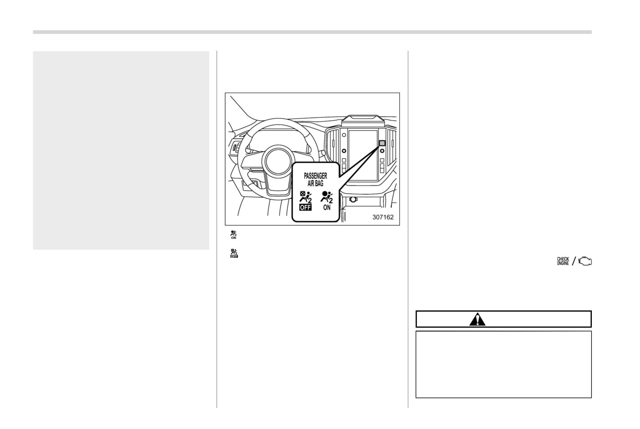
& Front passenger’s frontal air-
status of the front passenger’s SRS frontal
and consult a SUBARU dealer. Un-
bag ON and OFF indicator
airbag determined by the SUBARU ad-
less a technician checks and repairs
vanced frontal airbag system monitoring.
lights
the system as needed, the seatbelt
If the front passenger’s SRS frontal airbag
pretensioners and/or the SRS airbag
is activated, the passenger’s frontal airbag
will not operate properly in the event
ON indicator will illuminate while the OFF
of a collision, which may result in
indicator will remain off.
injury.
If the front passenger’s SRS frontal airbag
. Flashing or flickering of the warn-
is deactivated, the passenger’s frontal
ing light
airbag ON indicator will remain off while
the OFF indicator will illuminate.
. No illumination of the warning
light when the ignition switch is
With the ignition switch turned to the “ON”
first turned to the “ON” position
position, if both the ON and OFF indicators
remain illuminated or off simultaneously
. Continuous illumination of the
even after the system check period, the
warning light
system is malfunctioning. Contact your
. Illumination of the warning light
SUBARU dealer immediately for an in-
: Front passenger’s frontal airbag ON in-
while driving
dicator lights
spection.
: Front passenger’s frontal airbag OFF
For details about the components mon-
indicator lights
& CHECK ENGINE
itored by the warning light, refer to “SRS
The front passenger’s frontal airbag ON
warning light/Mal-
airbag system monitors” FP1 10.
and OFF indicators show you the status of
function indicator
the front passenger’s SRS frontal airbag.
light
The indicators are located as shown in the
illustration.
CAUTION
When the ignition switch is turned to the
If the CHECK ENGINE light illumi-
“ON” position, both the ON and OFF
nates while you are driving, have
indicators illuminate for 6 seconds during
your vehicle checked/repaired by
which time the system is checked. Follow-
your SUBARU dealer as soon as
ing the system check, both indicators turn
possible. Continued vehicle opera-
off for 2 seconds. After that, one of the
tion without having the emission
indicators illuminates depending on the
Warning and indicator lights
177
control system checked and re-
several driving trips. If the light does not
not turn off after the engine starts, stop the
paired as necessary could cause
turn off, take your vehicle to your author-
engine at the first safe opportunity and
serious damage, which may not be
ized SUBARU dealer immediately.
check the drive belt. If the belt is loose,
covered by your vehicle’s warranty.
broken or if the belt is in good condition but
! If the light is blinking
the light remains illuminated, contact your
If the light is blinking while driving, an
If this light illuminates steadily or blinks
nearest SUBARU dealer immediately.
engine misfire condition has been de-
while the engine is running, it may indicate
tected which may damage the emission
that there is at least one problem or
& Oil pressure warning
control system.
potential problem somewhere in the emis-
light
To prevent serious damage to the emis-
sion control system.
sion control system, you should do the
If this light illuminates when the engine is
! If the light illuminates steadily
following.
running, it may indicate that the engine oil
If the light illuminates steadily while driving
. Reduce vehicle speed.
pressure is low and the lubricating system
or does not turn off after the engine starts,
is not working properly.
. Avoid hard acceleration.
an emission control system malfunction
If the light illuminates while driving or does
. Avoid steep uphill grades.
has been detected.
not turn off after the engine starts, stop the
. Reduce the amount of cargo, if possi-
You should have your vehicle checked by
engine at the first safe opportunity and
ble.
an authorized SUBARU dealer immedi-
contact your nearest SUBARU dealer
. Stop towing a trailer as soon as
ately.
immediately.
possible.
NOTE
CAUTION
The CHECK ENGINE warning light may
This light also illuminates when the fuel
stop blinking and illuminate steadily after
Do not operate the engine with the
filler cap is not tightened until it clicks.
several driving trips. You should have your
oil pressure warning light illumi-
If you have recently refueled your vehicle,
vehicle checked by an authorized
nated. This may cause serious en-
the cause of the CHECK ENGINE warning
SUBARU dealer immediately.
gine damage.
light/malfunction indicator light illuminating
could be a loose or missing fuel filler cap.
& Charge warning light
Remove the cap and retighten it until it
& Engine low oil level
If this light illuminates when the engine is
clicks. Make sure nothing is interfering with
running, it may indicate that the charging
warning light
the sealing of the cap. Tightening the cap
system is not working properly.
will not make the CHECK ENGINE warn-
This light illuminates when the engine oil
ing light turn off immediately. It may take
If the light illuminates while driving or does
level decreases to the lower limit.
- CONTINUED -
178 Warning and indicator lights
If the warning light illuminates, check the
& Windshield washer
& Rear differential oil
engine oil level on a level surface. When
fluid warning light
temperature warning
the engine oil level is not within the normal
light (if equipped)
range, refill with engine oil. Refer to
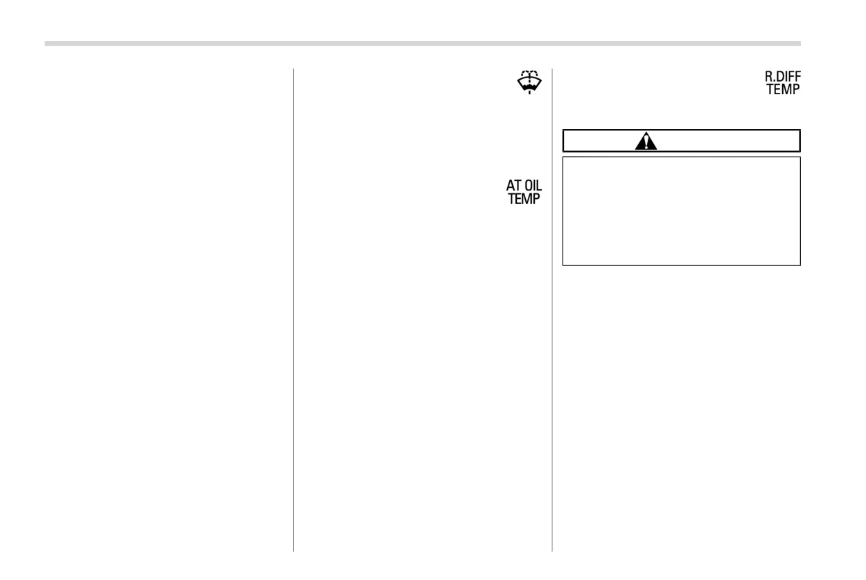
This light illuminates when the fluid level in
“Engine oil” FP486. After adding or chan-
the windshield washer fluid tank de-
CAUTION
ging the engine oil, warm up the engine
creases to the lower limit (approximately
and stop it on a level surface, then start the
0.6 US qt, 0.6 liters, 0.5 Imp qt).
If the R.DIFF TEMP warning light
engine after a lapse of 1 minute or more.
illuminates, reduce vehicle speed
Confirm that the warning light has turned
& AT OIL TEMP warning
and stop the vehicle in a safe loca-
off after the engine has started. If the
light
tion as soon as possible. Continuing
warning light does not turn off after refilling
to drive with this light illuminated
If this light illuminates when the engine is
the engine oil, or the light illuminates even
may damage the rear differential and
running, it may indicate that the transmis-
though the engine oil level is within the
other parts of the powertrain.
sion fluid temperature is too hot.
normal range, have the vehicle checked by
a SUBARU dealer.
If the light illuminates while driving, im-
If this light illuminates when the engine is
mediately stop the vehicle in a safe place
running, it may indicate that the rear
NOTE
and let the engine idle until the warning
differential oil temperature is too hot.
. The oil level will be detected by the
light turns off.
If the light illuminates while driving, reduce
system just after turning the ignition
vehicle speed and stop the vehicle in the
! Transmission control system warn-
switch to the “OFF” position. If the
nearest safe location. Park the vehicle for
ing
oil level is below the lower limit when
several minutes. After the light turns off,
the ignition switch is turned to the
If the “AT OIL TEMP” warning light flashes
you can start driving.
“ON” position, the engine low oil
after the engine has started, it may indicate
If the light does not turn off, contact the
level warning light will turn on.
that the transmission control system is not
nearest SUBARU dealer for service.
. When the vehicle is parked on a
working properly. Contact your nearest
steep slope, the engine low oil level
SUBARU dealer for service immediately.
NOTE
warning light may not illuminate
. If the tire pressures are not correct
even if the oil level is below the
and/or the tires are not all the same
lower limit to avoid erroneous light-
size and brand, the rear differential
ing.
will be heavily loaded when the
vehicle is driven, resulting in an
abnormally high oil temperature.
Warning and indicator lights
179
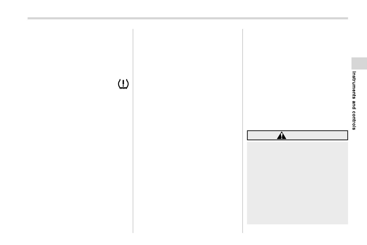
. The rear differential oil will deterio-
a low tire pressure telltale when one or
tire pressure as intended. TPMS malfunc-
rate if its temperature increases
more of your tires is significantly under-
tions may occur for a variety of reasons,
enough for the rear differential oil
inflated. Accordingly, when the low tire
including the installation of replacement or
temperature warning light to illumi-
pressure telltale illuminates, you should
alternate tires or wheels on the vehicle that
nate. It is advisable to have the rear
stop and check your tires as soon as
prevent the TPMS from functioning prop-
differential oil replaced as soon as
possible, and inflate them to the proper
erly. Always check the TPMS malfunction
possible.
pressure. Driving on a significantly under-
telltale after replacing one or more tires or
inflated tire causes the tire to overheat and
wheels on your vehicle to ensure that the
can lead to tire failure. Under-inflation also
replacement or alternate tires and wheels
& Low tire pressure
reduces fuel efficiency and tire tread life,
allow the TPMS to continue to function
warning light (U.S.-
and may affect the vehicle’s handling and
properly.
spec. models)
stopping ability.
Should the warning light illuminate steadily
When the ignition switch is turned to the
Please note that the TPMS is not a
after blinking for approximately one min-
“ON” position, the low tire pressure warn-
substitute for proper tire maintenance,
ute, have the system inspected by your
ing light will illuminate for approximately 2
and it is the driver’s responsibility to
nearest SUBARU dealer as soon as
seconds to check that the tire pressure
maintain correct tire pressure, even if
possible.
monitoring system (TPMS) is functioning
under-inflation has not reached the level
properly. If there is no problem and all tires
to trigger illumination of the TPMS low tire
WARNING
are properly inflated, the light will turn off.
pressure telltale.
If this light does not illuminate
Each tire, including the spare (if provided),
Your vehicle has also been equipped with
briefly after the ignition switch is
should be checked monthly when cold and
a TPMS malfunction indicator to indicate
turned on or the light illuminates
inflated to the inflation pressure recom-
when the system is not operating properly.
steadily after blinking for approxi-
mended by the vehicle manufacturer on
The TPMS malfunction indicator is com-
mately one minute, you should have
the vehicle placard or tire inflation pres-
bined with the low tire pressure telltale.
your Tire Pressure Monitoring Sys-
sure label. (If your vehicle has tires of a
When the system detects a malfunction,
tem checked at a SUBARU dealer as
different size than the size indicated on the
the telltale will flash for approximately one
soon as possible.
vehicle placard or tire inflation pressure
minute and then remain continuously
label, you should determine the proper tire
illuminated. This sequence will continue
If this light illuminates while driving,
inflation pressure for those tires.)
upon subsequent vehicle start-ups as long
never brake suddenly and keep
as the malfunction exists. When the mal-
driving straight ahead while gradu-
As an added safety feature, your vehicle
ally reducing speed. Then slowly
function indicator is illuminated, the sys-
has been equipped with a tire pressure
pull off the road to a safe place.
tem may not be able to detect or signal low
monitoring system (TPMS) that illuminates
– CONTINUED -
180 Warning and indicator lights
Otherwise an accident involving
checking tire pressure. The tire
switch is turned to the “ON”
serious vehicle damage and serious
pressure should be checked peri-
position.
personal injury could occur.
odically (at least monthly) using a
- The warning light illuminates
tire gauge. After any change to tire
If this light still illuminates while
when the ignition switch is
driving after adjusting the tire pres-
pressure(s), the tire pressure mon-
turned to the “ON” position,
itoring system will not re-check tire
sure, a tire may have significant
but it does not turn off even
inflation pressures until the vehicle
damage and a fast leak that causes
after the vehicle is started.
is first driven more than 20 mph (32
the tire to lose air rapidly. If you have
- The warning light illuminates
km/h). After adjusting the tire pres-
a flat tire, replace it with a spare tire
during driving.
sures, increase the vehicle speed to
as soon as possible.
at least 20 mph (32 km/h) to start the
When the warning light is on (and
When a spare tire is mounted or a
TPMS re-checking of the tire infla-
the brake system warning light is
wheel rim is replaced without the
tion pressures. If the tire pressures
off), the ABS function shuts
original pressure sensor/transmitter
are now above the severe low pres-
down. However, the conventional
being transferred, the Low tire pres-
sure threshold, the low tire pressure
brake system continues to oper-
sure warning light will illuminate
warning light should turn off a few
ate normally.
steadily after blinking for approxi-
minutes later. Therefore, be sure to
mately one minute. This indicates
The ABS warning light, Vehicle Dynamics
install the specified size for the front
the TPMS is unable to monitor all
and rear tires.
Control warning light, and brake system
four road wheels. Contact your
warning light illuminate simultaneously if
SUBARU dealer as soon as possible
the EBD system malfunctions. For further
for tire and sensor replacement and/
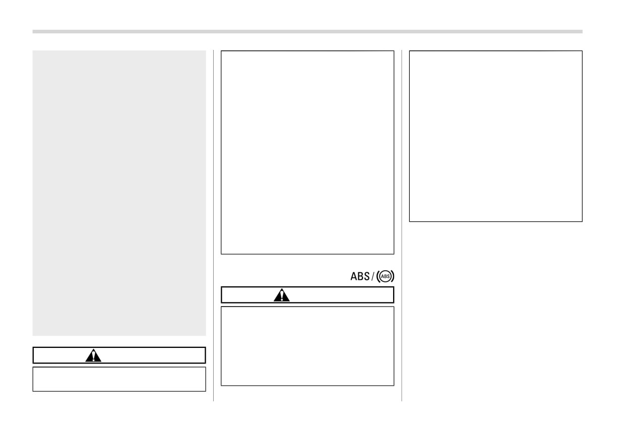
& ABS warning light
details of the EBD system malfunction
or system resetting.
warning, refer to “Electronic Brake Force
If the light illuminates steadily after
CAUTION
Distribution
(EBD) system warning”
blinking for approximately one min-
FP181.
ute, promptly contact a SUBARU
. If any of the following conditions
dealer to have the system inspected.
occur, we recommend that you
NOTE
have the ABS repaired at the first
If the warning light behavior is as
available opportunity by your
described in the following conditions,
CAUTION
SUBARU dealer.
the ABS may be considered normal.
- The warning light does not
. The warning light illuminates when
The tire pressure monitoring system
illuminate when the ignition
the ignition switch is turned to the
is NOT a substitute for manually
“ON” position and turns off approxi-
Warning and indicator lights
181
mately 2 seconds after the engine
the light remains illuminated,
! Electronic Brake Force Distribution
has started.
have the brakes inspected by a
(EBD) system warning
. The warning light illuminates right
SUBARU dealer immediately.
If the warning light remains on even though
after the engine is started but turns
. If at all in doubt about whether the
the parking brake is released, the brake
off immediately, remaining off.
brakes are operating properly, do
fluid level may be low or there could be a
. The warning light remains illumi-
not drive the vehicle. Have your
problem with the EBD system. Park the
nated after the engine has been
vehicle towed to the nearest
vehicle in a safe place immediately and
started, but it turns off while driving.
SUBARU dealer for repair.
contact a SUBARU dealer.
. The warning light illuminates during
driving, but it turns off immediately
! Electronic brake booster warning
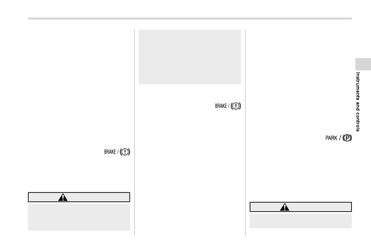
The brake system warning light has the
and remains off.
The brake system warning light illuminates
following functions.
when the electronic brake booster is
When driving with an insufficient battery
! Brake fluid level warning
malfunctioning. If the warning light illumi-
voltage, such as when the engine is jump
nates, promptly park in a safe location as
started, the ABS warning light may illumi-
This light illuminates when the brake fluid
soon as possible and contact your
nate. This is due to the low battery voltage
level has dropped to near the “MIN” level of
SUBARU dealer.
and does not indicate a malfunction. When
the brake fluid reservoir with the ignition
the battery becomes fully charged, the
switch in the “ON” position and with the
& Electronic parking
light will turn off.
parking brake fully released.
brake indicator light
If the brake system warning light should
& Brake system warn-
illuminate while driving (with the parking
! Parking brake indicator
ing light
brake fully released and with the ignition
The light illuminates with the parking brake
This light illuminates with the parking
switch positioned in “ON”), it could be an
applied while the ignition switch is in the
brake applied while the ignition switch is
indication of leaking of brake fluid or worn
“ON” position. It turns off when the parking
in the “ON” position. It turns off when the
brake pads. If this occurs, immediately
brake is fully released.
parking brake is fully released.
stop the vehicle at the nearest safe
! Electronic parking brake system
location and check the brake fluid level. If
warning
WARNING
the fluid level is below the “MIN” mark in
the reservoir, do not drive the vehicle.
. Driving with the brake system
WARNING
Have the vehicle towed to the nearest
warning light on is dangerous.
SUBARU dealer for repair.
. When you release the electronic
This indicates your brake system
parking brake while the engine is
may not be working properly. If
- CONTINUED -
182 Warning and indicator lights
running, the electronic parking
When the electronic parking brake
The electronic parking brake indicator light
brake indicator light will turn off.
switch is pulled to apply the electro-
flashes when the electronic parking brake
However, if the light still illumi-
nic parking brake while the ignition
system is malfunctioning. If the indicator
nates, stop the vehicle in a safe
switch is in the “LOCK”/“OFF” posi-
light flashes, promptly park in a safe
place immediately and have the
tion, the electronic parking brake
location as soon as possible and contact
system inspected by a SUBARU
indicator light illuminates, remains
your SUBARU dealer.
dealer.
illuminated for approximately
30
The electronic parking brake indicator light
seconds and then turns off.
remains illuminated when the parking
If at all in doubt about whether the
Even if the electronic parking brake
brake cannot be released even if the
brakes are operating properly, do
indicator light flashes, if the warning
parking brake switch is pushed. For de-
not drive the vehicle. Have your
light behavior is as described in the
tails, refer to
“Electronic parking brake”
vehicle towed to the nearest
following examples, the electronic
FP374.
SUBARU dealer for repair.
parking brake system is not mal-
If the electronic parking brake
! Parking brake apply inhibit warn-
functioning.
indicator light flashes, the elec-
ing
- The indicator light turns off when
tronic parking brake system may
the electronic parking brake is
The electronic parking brake indicator light
be malfunctioning. Immediately
released.
flashes for 10 seconds and a chirp sound
stop your vehicle in a safe loca-
The electronic parking brake indica-
will be heard if the parking brake switch is
tion, use tire stops under the tires
tor light may flash immediately after
operated when the parking brake cannot
to prevent the vehicle from mov-
the engine is started. However, it is
be applied.
ing and contact your SUBARU
not malfunctioning if the indicator
dealer. For details, refer to “Elec-
! Frequent operation warning
light turns off after the electronic
tronic parking brake” FP374.
The electronic parking brake indicator light
parking brake is released.
The electronic parking brake indica-
flashes for 10 seconds and a chirp sound
tor light may flash after the electro-
will be heard if the parking brake switch is
NOTE
operated too frequently. In this case, the
nic parking brake is frequently ap-
. When the ignition switch is turned to
operation of the parking brake switch is
plied and released. However, the
the “LOCK”/“OFF” position with the
restricted to protect the electronic parking
electronic parking brake system is
electronic parking brake applied, the
brake system.
not malfunctioning if the light turns
electronic parking brake indicator
off for a short period of time.
light remains illuminated for ap-
NOTE
proximately 30 seconds and then
Wait until the indicator light turns off.
turns off.
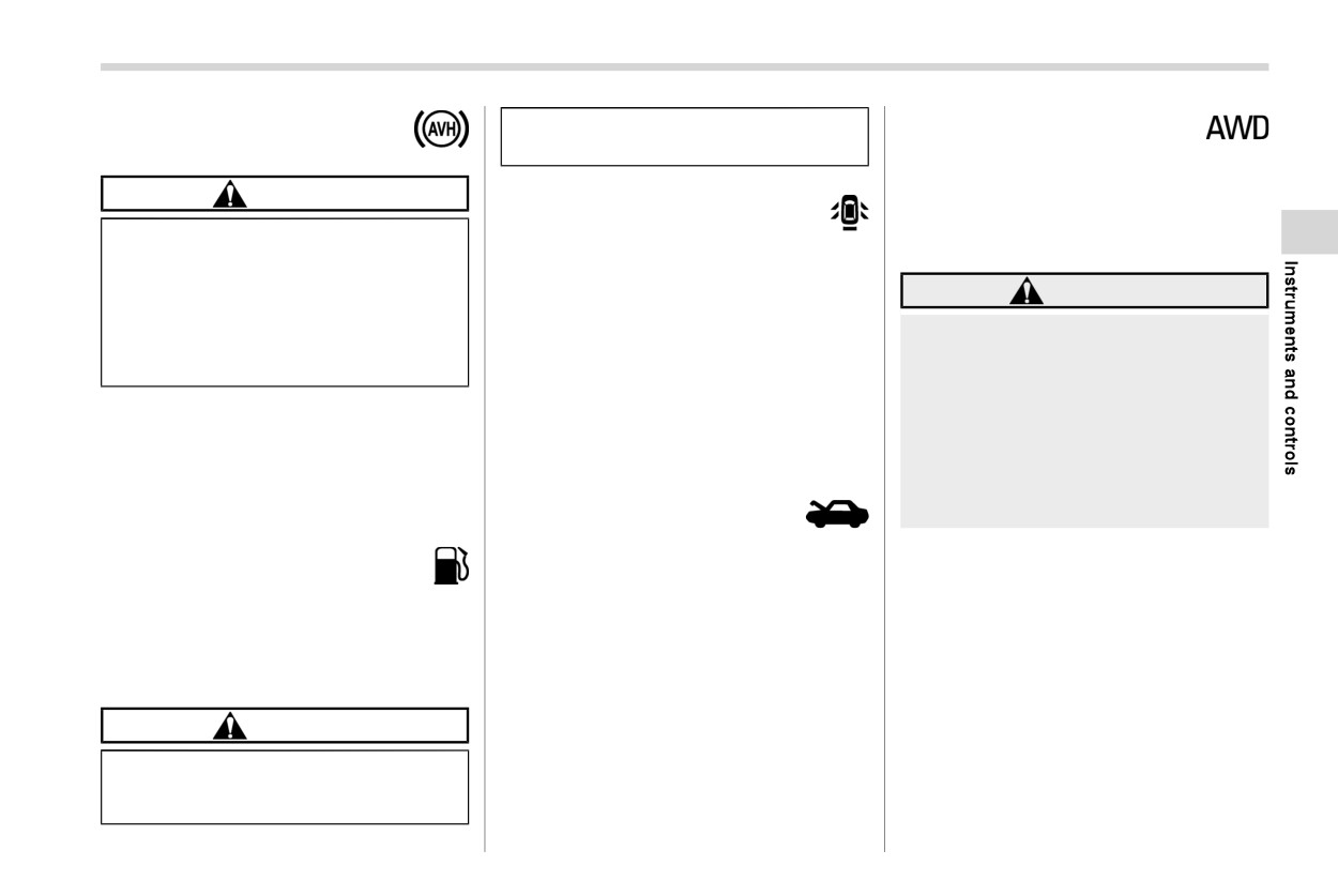
Warning and indicator lights
183
& Auto Vehicle Hold indi-
result of an empty tank could cause
& All-Wheel Drive warn-
cator light
damage to the engine.
ing light
This light blinks if the vehicle is driven with
CAUTION
& Door open warning light
tires of differing diameters fitted on the
wheels or with an excessively low air
If the Auto Vehicle Hold indicator
The warning light illuminates if any door or
pressure in any of the tires.
light does not illuminate even when
the rear gate is not fully closed. This
“Auto Vehicle Hold
(AVH)” is
function is effective even if the ignition
WARNING
touched to activate the Auto Vehicle
switch is in the “LOCK”/“OFF” or “ACC”
Hold function, the electronic parking
position, or the key is removed from the
If the AWD warning light flashes,
brake system may be malfunction-
ignition switch.
promptly park in a safe location then
ing.
check whether all four tires are the
For some models, only the open doors are
same diameter and whether any of
This indicator light illuminates when the
indicated by the warning lights.
the tires has a puncture or has lost
Auto Vehicle Hold is activated. This in-
Always make sure this light is not illumi-
air pressure for some other reason.
dicator blinks while the vehicle is stopped
Continuing to drive with the AWD
nated before you start to drive.
by the Auto Vehicle Hold function. For
warning light flashing can lead to
details, refer to “Auto Vehicle Hold func-
& Engine hood open
powertrain damage.
tion” FP376.
warning light
& Low fuel warning light
NOTE
The warning light illuminates if the engine
The low fuel warning light illuminates when
hood is not fully closed. This function is
If the temporary spare tire is used, the
the tank is nearly empty, at approximately
effective even if the ignition switch is in the
AWD warning light may flash. Use of the
2.6 US gal (10.0 liters, 2.2 Imp gal). It only
“LOCK”/“OFF” or “ACC” position, or the
temporary spare tire should therefore
operates when the ignition switch is in the
key is removed from the ignition switch
be restricted to the minimum time
“ON” position.
(models without
“keyless access with
necessary. Replace the temporary
push-button start system”).
spare tire with a conventional tire as
CAUTION
soon as possible.
Always make sure this light is not illumi-
nated before you start to drive.
Promptly put fuel in the tank when-
ever the low fuel warning light
illuminates. Engine misfires as a
- CONTINUED -