Subaru Legacy III (2000-2003 year). Manual - part 943


  Index      Subaru     Subaru Legacy III - service repair manual 2000-2003 year


Search            


Content   ..  941  942  943  944   ..


Subaru Legacy III (2000-2003 year). Manual - part 943


GW-32

GLASS/WINDOWS/MIRRORS

REAR WINDOW DEFOGGER

18.Rear Window Defogger
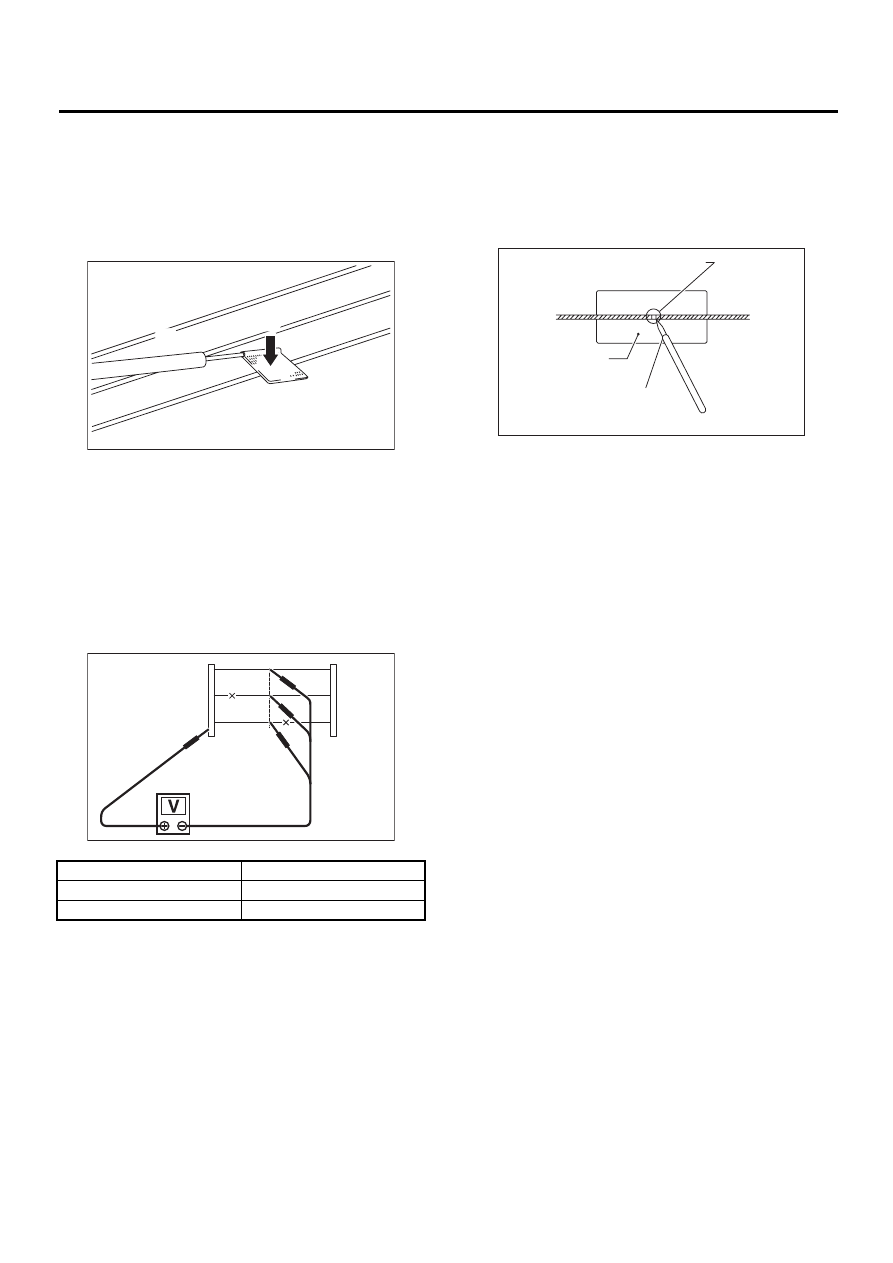
A: INSPECTION

1) Turn ignition switch to ON.
2) Turn defogger switch to ON.
3) Wrap tips of tester pins with aluminum foil to
avoid damage to heat wire.

4) Measure voltage at wire center (A) with DC volt-
meter.

Standard voltage:

Approx. 6 volts

NOTE:
• If the measured value is 12 volts, heat wire is
open between wire center and positive (+) end.
• If zero volt, heat wire is open between wire cen-
ter and ground. 
5) Apply positive lead of voltmeter to positive termi-
nal of voltmeter, and then move negative lead
along the wire up to the negative terminal end. If
voltage changes from zero to several volts during
movement of lead, heat wire is open at the voltage
change point.

B: REPAIR

1) Clean broken portion with alcohol or white gaso-
line.
2) Mask both side of wire with thin film.
3) Apply conductive silver composition (DUPONT
No. 4817) to broken portion.

4) After repair, check wire.

(1) Tester probe

(2) Tin foil

(3) Heat wire

(4) PRESS

Voltage

Criteria

Approx. 6 V

OK

Approx. 12 V or 0 V

Broken

GW-00126

( 1 )

( 2 )

( 3 )

( 4 )

GW-00127

( A )

(1) Broken portion

(2) Masking thin film

(3) Conductive silver composition

(4) Broken wire

GW-00128

( 1 )

( 2 )

( 3 )

( 4 )

GW-33

GLASS/WINDOWS/MIRRORS

OUTER MIRROR ASSEMBLY

19.Outer Mirror Assembly

A: REMOVAL

1) Remove door trim.  <Ref. to EI-30, REMOVAL,
Front Door Trim.>
2) Remove sealing cover to disconnect mirror con-
nector.

3) Loosen screws to remove mirror assembly.

B: INSTALLATION

Install in the reverse order of removal.

GW-00129

GW-00130

GW-34

GLASS/WINDOWS/MIRRORS

OUTER MIRROR ASSEMBLY

C: INSPECTION

Check to ensure that outer mirror moves properly when battery voltage is applied to terminals.
Mirror heater not-equipped model:

If NG, replace the mirror.
Mirror heater equipped model:

If NG, replace the mirror.

Switch position

Terminal No.

OFF

UP

1 (+) and 3 (

)

DOWN

3 (+) and 1 (

)

LEFT

2 (+) and 3 (

)

RIGHT

3 (+) and 2 (

)

Switch position

Terminal No.

OFF

UP

2 (+) and 4 (

)

DOWN

4 (+) and 2 (

)

LEFT

3 (+) and 4 (

)

RIGHT

4 (+) and 3 (

)

GW-35

GLASS/WINDOWS/MIRRORS

OUTER MIRROR

20.Outer Mirror

A: REPLACEMENT

1) Remove the door mirror assembly. <Ref. to GW-
33, REMOVAL, Outer Mirror Assembly.>
2) Warm the area around the mirror holder (A) with
a hair drier until the edges of the mirror holder be-
come soft (about 2 or 3 minutes with a 1,000 W dri-
er.)
3) Use a flat-bladed screwdriver without sharp edg-
es to lift the mirror out of the mirror holder (A). (Also
remove the connector from the back of mirrors with
heaters.)

4) Warm the area around the mirror holder (A) with
a hair drier until the edges of the mirror holder (A)
become soft (about 2 or 3 minutes with a 1,000 W
drier.)
5) Remove the backing of the new two-sided tape,
and push the mirror in to install it.

NOTE:
Unless the mirror holder is warmed sufficiently, the
mirror holder edges may be damaged or the mirror
cracked.

GW-00131

( A )


Content   ..  941  942  943  944   ..