Subaru Legacy III (2000-2003 year). Manual - part 523


  Index      Subaru     Subaru Legacy III - service repair manual 2000-2003 year


Search            


Content   ..  521  522  523  524   ..


Subaru Legacy III (2000-2003 year). Manual - part 523


CS-12

CONTROL SYSTEMS

SELECT CABLE

3. Select Cable

A: REMOVAL

1) Set the vehicle on a lift.
2) Disconnect negative cable from battery.
3) Prior to removal, set lever to “N” position.
4) Lift-up the vehicle.
5) Remove front, center, rear exhaust pipe and
muffler. (Non-turbo model)
2.0 L and 2.5 L with OBD models
<Ref. to EX(H4SO)-5, REMOVAL, Front Exhaust
Pipe.>, <
Ref. to EX(H4SO)-9, REMOVAL, Rear
Exhaust Pipe.>
 and <Ref. to EX(H4SO)-10, RE-
MOVAL, Muffler.>
2.0 L and 2.5 L without OBD models
<Ref. to EX(H4SOw/oOBD)-9, REMOVAL, Front
Exhaust Pipe.>, <
Ref. to EX(H4SOw/oOBD)-13,
REMOVAL, Rear Exhaust Pipe.> 
and <Ref. to
EX(H4SOw/oOBD)-14, REMOVAL, Muffler.>
3.0 L model
<Ref. to EX(H6DO)-5, REMOVAL, Front Exhaust
Pipe.>, <
Ref. to EX(H6DO)-8, REMOVAL, Rear
Exhaust Pipe.> an
d <Ref. to EX(H6DO)-9, RE-
MOVAL, Muffler.>
6) Remove center and rear exhaust pipes and muf-
fler. (Turbo model)
<Ref. to EX(H4DOSTC)-7, REMOVAL, Center Ex-
haust Pipe.>,
 <Ref. to EX(H4DOSTC)-12, RE-
MOVAL, Rear Exhaust Pipe.> and <Ref
. to
EX(H4DOSTC)-13, REMOVAL, Muffler.>
7) Remove heat shield cover. (If equipped)

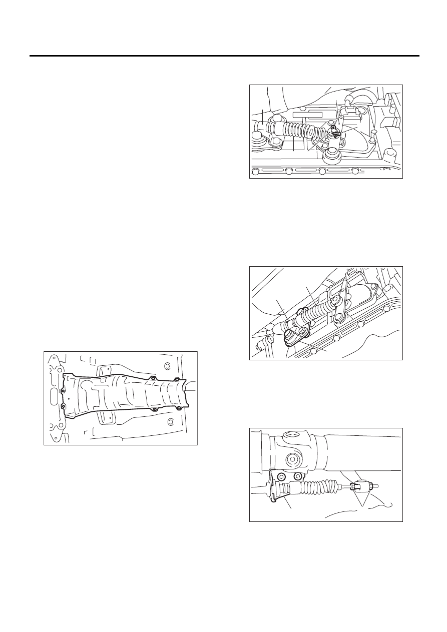
8) Remove snap pin and washer from range select
lever.

9) Remove plate assembly from transmission
case.

10) Disconnect cable from select lever and then re-
move cable bracket.

11) Remove select cable from plate assembly.

AT-00682

(A) Range select lever

(B) Snap pin

(C) Select cable

(D) Clamp

(E) Washer

(A) Select cable

(B) Plate ASSY

(C) Clamp

(A) Adjusting nuts

(B) Cable bracket

( A )

( B )

( C )

( D )

( E )

CS-00036

CS-00037

( A )

( B )

( C )

CS-00038

( A )

( B )

CS-13

CONTROL SYSTEMS

SELECT CABLE

B: INSTALLATION

1) Install select cable to plate assembly.

Tightening torque:

18 N·m (1.8 kgf-m, 13.0 ft-lb)

2) Install select cable to range select lever.
3) Install plate assembly to transmission.

Tightening torque:

T: 24.5 N·m (2.5 kgf-m, 18.1 ft-lb)

4) Install washer and snap pin to range select lever.

5) Insert the thread portion of the other inner cable
and into the connector hole of the select lever, and
fix the other outer cable end to the bracket.

Tightening torque:

18 N·m (1.8 kgf-m, 13 ft-lb)

6) Move the select lever to the “N” position, then
adjust the select cable position. <Ref. to CS-14,
ADJUSTMENT, Select Cable.>

7) Install heat shield cover.

8) Install front, center, rear exhaust pipe and muf-
fler. (Non-turbo model)
2.0 L and 2.5 L with OBD models
<Ref. to EX(H4SO)-6, INSTALLATION, Front Ex-
haust Pipe.>, <Ref
. to EX(H4SO)-9, INSTALLA-
TION, Rear Exhaust Pipe.> and <
Ref. to
EX(H4SO)-10, INSTALLATION, Muffler.>
2.0 L and 2.5 L without OBD models
<Ref. to EX(H4SOw/oOBD)-10, INSTALLATION,
Front Exhaust Pipe.>,
 <Ref. to EX(H4SOw/oOBD)-
13, INSTALLATION, Rear Exhaust Pipe.> an
d
<Ref. to EX(H4SOw/oOBD)-14, INSTALLATION,
Muffler.>
3.0 L model
<Ref. to EX(H6DO)-6, INSTALLATION, Front Ex-
haust Pipe.>, <Ref
. to EX(H6DO)-8, INSTALLA-
TION, Rear Exhaust Pipe.> and <
Ref. to
EX(H6DO)-9, INSTALLATION, Muffler.>
9) Install center and rear exhaust pipes and muf-
fler. (Turbo model)
<Ref. to EX(H4DOSTC)-8, INSTALLATION, Cen-
ter Exhaust Pipe.>
, <Ref. to EX(H4DOSTC)-12, IN-
STALLATION, Rear Exhaust Pipe.> and
 <Ref. to
EX(H4DOSTC)-13, INSTALLATION, Muffler.>

C: INSPECTION

Check the removed cable and replace if damaged,
rusty, or malfunctioning.
1) Check for smooth operation of the cable.
2) Check the inner cable for damage and rust.
3) Check the outer cable for damage, bends, and
cracks.
4) Check the boot for damage, cracks, and deterio-
ration.
5) Move select lever from “P” position to “1” posi-
tion. You should be able to feel the detentes in
each position. If the detentes cannot be felt or the
position pointer is improperly aligned, adjust the ca-
ble.

(A) Select cable

(B) Plate ASSY

(A) Range select lever

(B) Snap pin

(C) Select cable

(D) Clamp

(E) Washer

CS-00039

( A )

( B )

T

( A )

( B )

( C )

( D )

( E )

CS-00036

AT-00682

CS-14

CONTROL SYSTEMS

SELECT CABLE

D: ADJUSTMENT

1) Prior to removal, set lever to “N” position.
2) Remove rear exhaust pipe and muffler.
2.0 L (non-turbo) and 2.5 L with OBD models
<Ref. to EX(H4SO)-9, REMOVAL, Rear Exhaust
Pipe.> and 
<Ref. to EX(H4SO)-10, REMOVAL,
Muffler.>
2.0 L (non-turbo) and 2.5 L without OBD models
<Ref. to EX(H4SOw/oOBD)-13, REMOVAL, Rear
Exhaust Pipe.> and
 <Ref. to EX(H4SOw/oOBD)-
14, REMOVAL, Muffler.>
3.0 L model
<Ref. to EX(H6DO)-8, REMOVAL, Rear Exhaust
Pipe.> and <
Ref. to EX(H6DO)-9, REMOVAL, Muf-
fler.>
Turbo model
<Ref. to EX(H4DOSTC)-12, REMOVAL, Rear Ex-
haust Pipe.> and 
<Ref. to EX(H4DOSTC)-13, RE-
MOVAL, Muffler.>
3) Remove heat shield cover. (If equipped)

4) Loosen the adjusting nut on each side.

5) Turn adjusting nut B until it lightly touches the
connector.

6) While preventing adjusting nut B from moving
with a wrench, tighten adjusting nut A.

Tightening torque:

7.5 N·m (0.76 kgf-m, 5.5 ft-lb)

7) After completion of fitting, make sure that the se-
lect lever operates smoothly all across the operat-
ing range.
8) Install in the reverse order of removal.

(A) Adjusting nut A

(B) Adjusting nut B

AT-00682

CS-00040

( A )

( B )

(A) Front side

(B) Select lever

(C) Connector

(D) Adjusting nut B

(E) Contact point

(F) Adjusting nut A

(A) Adjusting nut A

(B) Adjusting nut B

CS-00041

( A )

( B )

( C )

( D )

( E )

( F )

CS-00042

( A )

( B )

CS-15

CONTROL SYSTEMS

MT GEAR SHIFT LEVER

4. MT Gear Shift Lever

A: REMOVAL

1) Set the vehicle on a lift.
2) Disconnect negative cable from battery.
3) Remove gear shift knob.
4) Remove console box. <Ref. to EI-34, REMOV-
AL, Console Box.>
5) Remove the clamp.

6) Remove the boot and insulator assembly.

7) Remove the drive select cable. (Dual-range
model)
<Ref. to CS-23, REMOVAL, Drive Select Cable.>
8) Remove the plate assembly from body.

9) Lift-up the vehicle.
10) Remove rear exhaust pipe and muffler.
2.0 L (non-turbo) and 2.5 L with OBD models
<Ref. to EX(H4SO)-9, REMOVAL, Rear Exhaust
Pipe.> and 
<Ref. to EX(H4SO)-10, REMOVAL,
Muffler.>
2.0 L (non-turbo) and 2.5 L without OBD models

<Ref. to EX(H4SOw/oOBD)-13, REMOVAL, Rear
Exhaust Pipe.>
 and <Ref. to EX(H4SOw/oOBD)-
14, REMOVAL, Muffler.>
3.0 L model
<Ref. to EX(H6DO)-8, REMOVAL, Rear Exhaust
Pipe.> 
and <Ref. to EX(H6DO)-9, REMOVAL, Muf-
fler.>
Turbo model
<Ref. to EX(H4DOSTC)-12, REMOVAL, Rear Ex-
haust Pipe.> and <Ref
. to EX(H4DOSTC)-13, RE-
MOVAL, Muffler.>
11) Remove heat shield cover. (If equipped)

12) Remove stay from transmission bracket.

13) Remove rod from joint.

CS-00155

CS-00156

CS-00157

(A) Stay

(B) Transmission bracket

(A) Stay

(B) Rod

AT-00682

CS-00050

( A )

( B )

CS-00051

( A )

( B )


Content   ..  521  522  523  524   ..