Subaru Legacy III (2000-2003 year). Manual - part 524


  Index      Subaru     Subaru Legacy III - service repair manual 2000-2003 year


Search            


Content   ..  522  523  524  525   ..


Subaru Legacy III (2000-2003 year). Manual - part 524


CS-16

CONTROL SYSTEMS

MT GEAR SHIFT LEVER

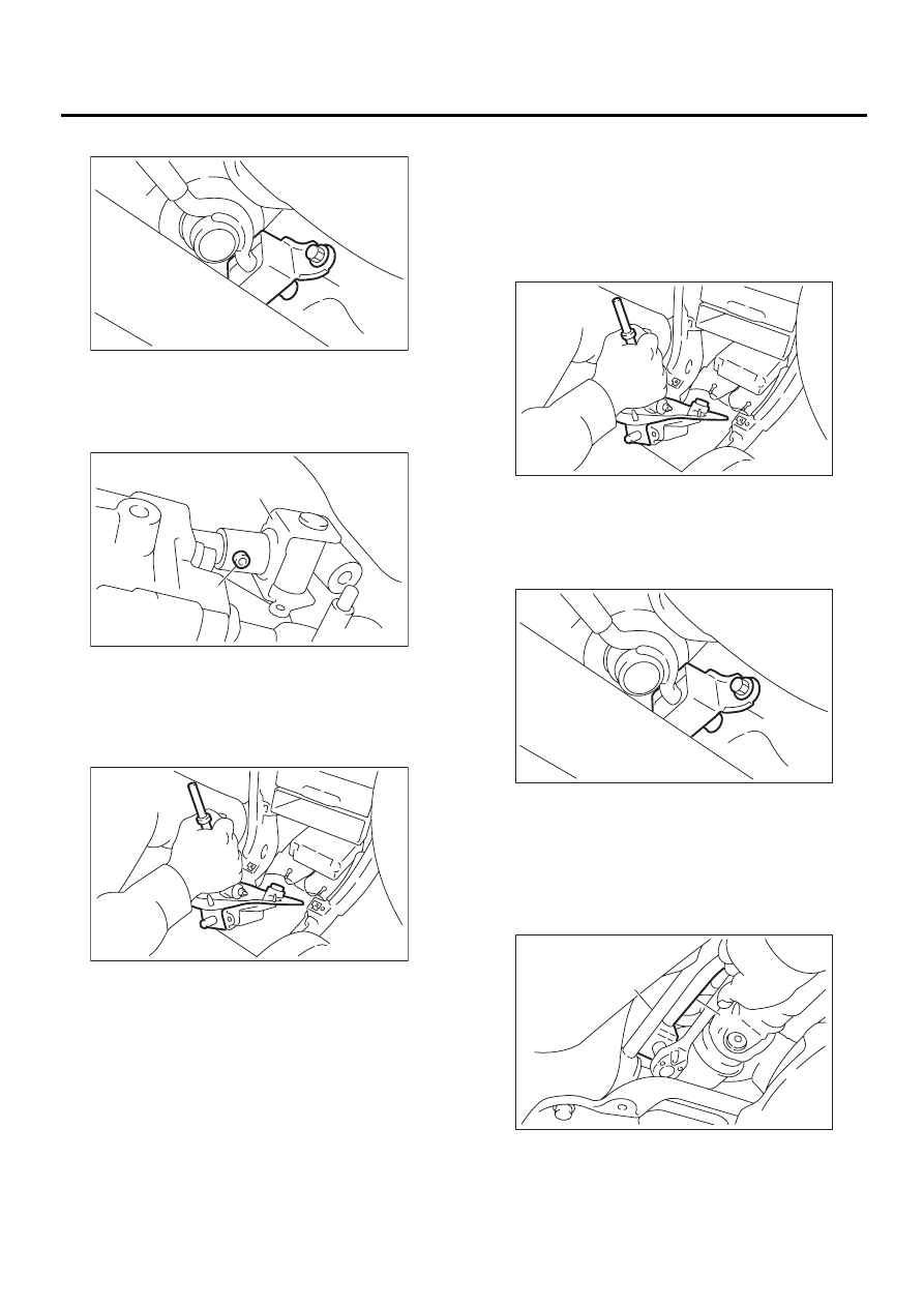
14) Remove cushion rubber from body.

15) Remove joint and then extract spring pin.

16) Lower the vehicle.
17) Remove gear shift lever.

B: INSTALLATION

1) Install the joint to the transmission and secure
with the spring pin.
2) Insert gear shift lever from room side.

NOTE:
After inserting rod and stay, temporarily put them
onto transmission mount.

3) Lift-up the vehicle.
4) Mount cushion rubber on the body.

Tightening torque:

18 N·m (1.8 kgf-m, 13.0 ft-lb)

5) Connect rod to the joint.

Tightening torque:

18 N·m (1.8 kgf-m, 13.0 ft-lb)

(A) Stay

(B) Cushion rubber

(A) Joint

(B) Spring pin

CS-00052

( A )

( B )

CS-00053

( A )

( B )

CS-00054

(A) Stay

(B) Cushion rubber

(A) Stay

(B) Rod

CS-00054

CS-00052

( A )

( B )

CS-00051

( A )

( B )

CS-17

CONTROL SYSTEMS

MT GEAR SHIFT LEVER

6) Connect stay to transmission bracket.

Tightening torque:

18 N·m (1.8 kgf-m, 13.0 ft-lb)

7) Install heat shield cover. (If equipped)

8) Install rear exhaust pipe and muffler.
2.0 L (non-turbo) and 2.5 L with OBD models
<Ref. to EX(H4SO)-9, INSTALLATION, Rear Ex-
haust Pipe.> an
d <Ref. to EX(H4SO)-10, INSTAL-
LATION, Muffler.>
2.0 L (non-turbo) and 2.5 L without OBD models
<Ref. to EX(H4SOw/oOBD)-13, INSTALLATION,
Rear Exhaust Pipe.> and
 <Ref. to EX(H4SOw/
oOBD)-14, INSTALLATION, Muffler.>
3.0 L model
<Ref. to EX(H6DO)-8, INSTALLATION, Rear Ex-
haust Pipe.> and <
Ref. to EX(H6DO)-9, INSTAL-
LATION, Muffler.>
Turbo model
<Ref. to EX(H4DOSTC)-12, INSTALLATION, Rear
Exhaust Pipe.> and <
Ref. to EX(H4DOSTC)-13,
INSTALLATION, Muffler.>

9) Install the plate assembly to body.

Tightening torque:

7.5 N·m (0.76 kgf-m, 5.5 ft-lb)

10) Install the drive select cable. (Dual-range mod-
el)
<Ref. to CS-23, INSTALLATION, Drive Select Ca-
ble.>
11) Install the boot and insulator assembly to vehi-
cle in proper direction.

12) Install the clamp.
13) Install console box. <Ref. to EI-34, INSTALLA-
TION, Console Box.>

(A) Stay

(B) Transmission bracket

CS-00050

( A )

( B )

AT-00682

CS-00157

CS-00156

CS-18

CONTROL SYSTEMS

MT GEAR SHIFT LEVER

C: DISASSEMBLY

1) Disassemble lock wire.

2) Remove rod from lever.

3) Remove snap ring from bushing B, then discon-
nect stay.

4) Remove boot from gear shift lever.

5) Remove bushing and cushion rubber from stay.

6) Remove O-ring, then disconnect bushing B.

7) Draw out spring pin, then remove bushing A
from gear shift lever.

(A) Lock wire

(B) Stay

(A) Rod

(B) Lever

(C) Stay

(A) Snap ring

(B) Bushing B

(C) Boot

CS-00055

( A )

( B )

CS-00056

( A )

( B )

( C )

CS-00057

( A )

( B )

( C )

(A) Bushing

(B) Stay

(C) Cushion rubber

(A) O-ring

(B) O-ring

(C) Bushing B

(A) Spring pin

(B) Bushing A

CS-00058

( A )

( B )

( C )

CS-00059

( A )

( B )

( C )

CS-00060

( A )

( B )

CS-19

CONTROL SYSTEMS

MT GEAR SHIFT LEVER

D: ASSEMBLY

1) Clean all parts before assembly.
2) Mount the bushing and cushion rubber on the
stay.

3) Mount each part; boot, O-ring, bushing A, spac-
er, bushing B, bushing and spring pin on the gear
shift lever.

NOTE:
• Always use new O-rings.
• Apply grease [SUNLIGHT 2 (Part No.
003602010 or equivalent] to the inner and side sur-
faces of the bushing when installing the spacer.

4) Insert the gear shift lever into the boot hole.

5) Install snap ring and stay to the bushing B.

6) Tighten with lock wire to the extent that the boot
will not come off.

NOTE:
Always use new lock wire.

7) Insert the rod into the boot hole.
8) Connect rod to lever.

Tightening torque:

11.8 N·m (1.2 kgf-m, 8.7 ft-lb)

(A) Bushing

(B) Cushion rubber

(A) Boot

(B) O-ring

(C) Bushing

(D) Spacer

(E) Bushing A

(F) Bushing B

(G) Spring pin

(H) O-ring

CS-00061

( A )

( B )

CS-00062

( F )

( D )

( C )

( E )

( G )

( H )

( B )

( A )

(A) Snap ring

(B) Bushing B

(A) Lock wire

(B) Stay

(A) Rod

(B) Lever

(C) Stay

CS-00063

( A )

( B )

CS-00055

( A )

( B )

CS-00056

( A )

( B )

( C )


Content   ..  522  523  524  525   ..