Subaru Legacy III (2000-2003 year). Manual - part 522


  Index      Subaru     Subaru Legacy III - service repair manual 2000-2003 year


Search            


Content   ..  520  521  522  523   ..


Subaru Legacy III (2000-2003 year). Manual - part 522


CS-8

CONTROL SYSTEMS

SELECT LEVER

2. Select Lever

A: REMOVAL

1) Set the vehicle on a lift.
2) Disconnect negative cable from battery.
3) Move the select lever to the “N” position.
4) Lift-up the vehicle.
5) Remove rear exhaust pipe and muffler.
2.0 L and 2.5 L with OBD models
<Ref. to EX(H4SO)-9, REMOVAL, Rear Exhaust
Pipe.> and 
<Ref. to EX(H4SO)-10, REMOVAL,
Muffler.>
2.0 L and 2.5 L without OBD models
<Ref. to EX(H4SOw/oOBD)-13, REMOVAL, Rear
Exhaust Pipe.> and
 <Ref. to EX(H4SOw/oOBD)-
14, REMOVAL, Muffler.>
3.0 L model
<Ref. to EX(H6DO)-8, REMOVAL, Rear Exhaust
Pipe.> and <
Ref. to EX(H6DO)-9, REMOVAL, Muf-
fler.>
Turbo model
<Ref. to EX(H4DOSTC)-12, REMOVAL, Rear Ex-
haust Pipe.> and 
<Ref. to EX(H4DOSTC)-13, RE-
MOVAL, Muffler.>
6) Remove heat shield cover. (If equipped)

7) Disconnect cable from select lever and then re-
move cable bracket.

8) Lower the vehicle.
9) Remove console box.  <Ref. to EI-34, REMOV-
AL, Console Box.>

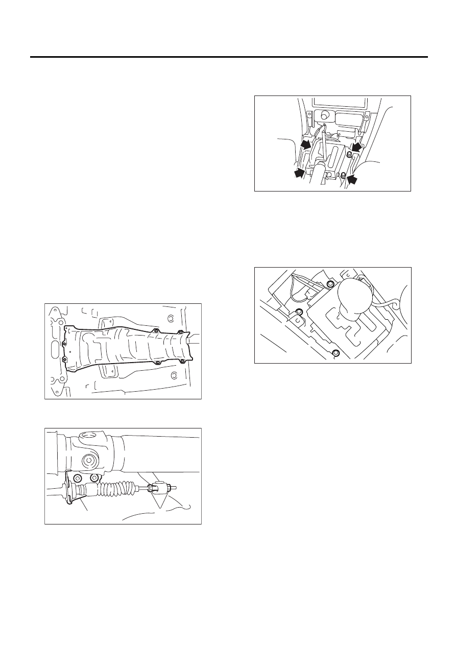
10) Disconnect the connectors, then remove the
four bolts to take out the select lever assembly from
the body.

B: INSTALLATION

1) Mount the select lever onto the vehicle body.
2) Tighten the four bolts to install the select lever to
the vehicle body, then connect connector.

Tightening torque:

13 N·m (1.3 kgf-m, 9.4 ft-lb)

3) Install console box. <Ref. to EI-34, INSTALLA-
TION, Console Box.>
4) Set location of select lever at “N” position.
5) Lift-up the vehicle.
6) Set location of range select lever to “N” position.
7) Insert the thread portion of the other inner cable
and into the connector hole of the select lever, and
fix the other outer cable end to the bracket.

Tightening torque:

18 N·m (1.8 kgf-m, 13.0 ft-lb)

8) Adjust the select cable position. <Ref. to CS-14,
ADJUSTMENT, Select Cable.>
9) After completion of fitting, make sure that the se-
lect lever operates smoothly all across the operat-
ing range.
10) Install heat shield cover. (If equipped)

(A) Adjusting nuts

(B) Cable bracket

AT-00682

CS-00017

( A )

( B )

CS-00018

CS-00019

CS-9

CONTROL SYSTEMS

SELECT LEVER

11) Install rear exhaust pipe and muffler.
2.0 L and 2.5 L with OBD models
<Ref. to EX(H4SO)-9, INSTALLATION, Rear Ex-
haust Pipe.> an
d <Ref. to EX(H4SO)-10, INSTAL-
LATION, Muffler.>
2.0 L and 2.5 L without OBD models
<Ref. to EX(H4SOw/oOBD)-13, INSTALLATION,
Rear Exhaust Pipe.> and
 <Ref. to EX(H4SOw/
oOBD)-14, INSTALLATION, Muffler.>
3.0 L model
<Ref. to EX(H6DO)-8, INSTALLATION, Rear Ex-
haust Pipe.> and <
Ref. to EX(H6DO)-9, INSTAL-
LATION, Muffler.>
Turbo model
<Ref. to EX(H4DOSTC)-12, INSTALLATION, Rear
Exhaust Pipe.> and <
Ref. to EX(H4DOSTC)-13,
INSTALLATION, Muffler.>
12) Inspect the following items. If the following in-
spection reveals problems, adjust the select cable
and inhibitor switch. <Ref. to CS-14, ADJUST-
MENT, Select Cable.>  
and  <Ref. to AT-50, AD-
JUSTMENT, Inhibitor Switch.>

(1) The engine starts operating when select le-
ver is in position “P” and “N”, but not in other po-
sitions.
(2) The back-up light is lit when the select lever
is in position “R”, but not in other positions.
(3) Select lever and indicator positions are
matched.

C: DISASSEMBLY

1. EXCEPT SPORT SHIFT MODEL

1) Remove grip.
2) Remove bulb and then remove indicator.

NOTE:
Be careful not to break the bulb during removal.

3) Remove blind.
4) Remove clips and then remove guide plate.

5) Remove cap and then extract spring pin.

(A) Grip

(B) Indicator

(C) Bulb

(A) Clips

(B) Guide plate

(A) Spring pin

(B) Arm ASSY

CS-00179

( A )

( B )

( C )

CS-00180

( A )

( A )

( B )

CS-00181

( A )

( B )

CS-10

CONTROL SYSTEMS

SELECT LEVER

6) Remove arm assembly then take away lever
from base plate.

2. SPORT SHIFT MODEL

1) Remove the packing.
2) Remove the grip.

3) Remove the bulb, and then remove the indicator.

NOTE:
Be careful not to break the bulb during removal.

4) Remove the blind.

5) Remove the clips, and then remove the guide
plate.

6) Remove the screw.

7) Remove the bushing.

(A) Arm ASSY

(B) Lever

(C) Base plate

(A) Indicator

(B) Bulb

CS-00182

( A )

( B )

( C )

CS-00144

CS-00183

( A )

( B )

(A) Clips

(B) Guide plate

CS-00184

( A )

( A )

( B )

CS-00185

CS-00186

CS-11

CONTROL SYSTEMS

SELECT LEVER

8) Remove the clip, and then remove the rod and
the spring.

9) Remove the bolt.

10) Remove the bracket guide assembly.

11) Remove the grommet, and then extract spring
pin from the top.

12) Remove the arm assembly and then take away
the lever and arm bracket from base plate.

13) Remove the spring, and then remove the de-
tent arm.

D: ASSEMBLY

1) Clean all parts before assembly.
2) Apply grease [SUNLIGHT 2 (Part No.
003602010) or equivalent] to each parts. <Ref. to
CS-3, AT SELECT LEVER (EXCEPT SPORT
SHIFT MODEL), COMPONENT, General Descrip-
tion.> and
 <Ref. to CS-4, AT SELECT LEVER
(SPORT SHIFT MODEL), COMPONENT, General
Description.>
3) Assembly is in the reverse order of disassembly.
4) After completion of fitting, transfer the select le-
ver to range “P” — “1”, then check whether the in-
dicator and select lever agree, whether the pointer
and position mark agree and what the operating
force is.

E: INSPECTION

1) Inspect the removed parts by comparing with
new ones for deformation, damage and wear. Cor-
rect or replace if defective.
2) Confirm the following parts for operating condi-
tion before assembly. Moving condition of the se-
lect lever assembly, it should move smoothly.

(A) Clip

(B) Bushing

(C) Spring

(D) Rod

CS-00150

( A )

( C )

( D )

( B )

CS-00187

CS-00188

CS-00211

(A) Arm ASSY

(B) Lever

(C) Base plate

(D) Arm bracket

CS-00189

( A )

( A )

( B )

( C )


Content   ..  520  521  522  523   ..