Subaru Impreza 3 / Impreza WRX / Impreza WRX STI. Manual - part 770


  Index      Subaru     Subaru Impreza 3 / Impreza WRX / Impreza WRX STI - service repair manual 2008-2014 year


Search            


Content   ..  768  769  770  771   ..


Subaru Impreza 3 / Impreza WRX / Impreza WRX STI. Manual - part 770


IM(diag)-15

Diagnostic Procedure with Diagnostic Trouble Code (DTC)

IMMOBILIZER (DIAGNOSTICS)

10.Diagnostic Procedure with Diagnostic Trouble Code (DTC)

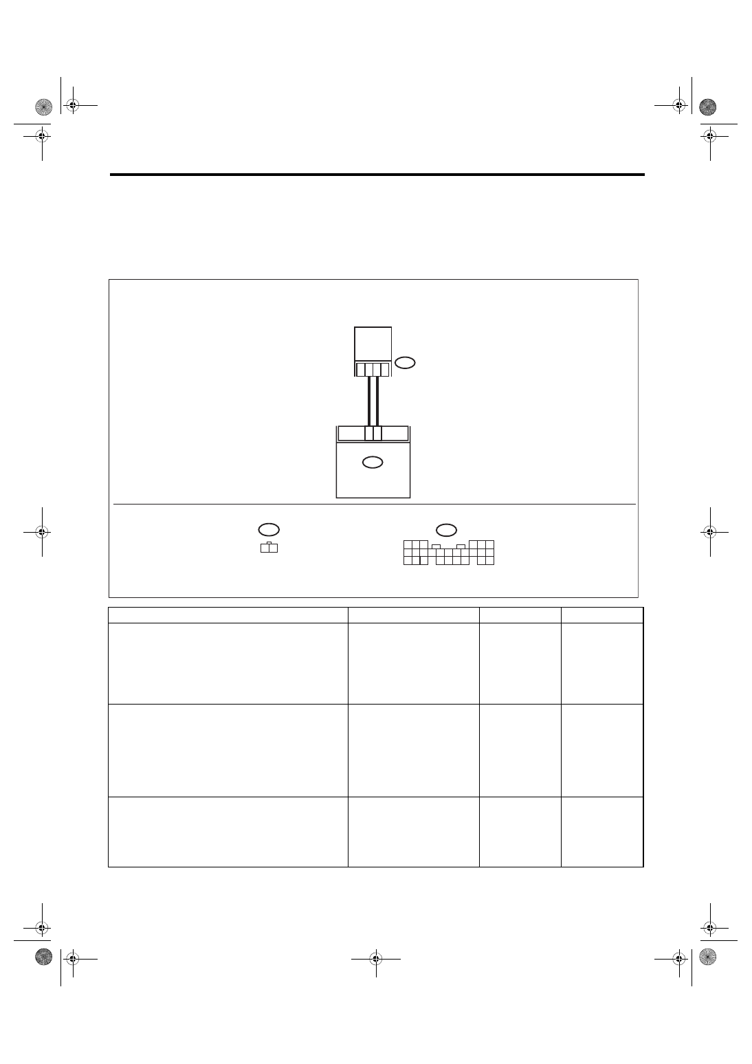
A: DTC B1570 ANTENNA

DTC DETECTING CONDITION:

Faulty antenna

WIRING DIAGRAM:

Immobilizer system <Ref. to WI-158, WIRING DIAGRAM, Immobilizer System.>

Step

Check

Yes

No

1

CHECK ANTENNA CIRCUIT.
1) Turn the ignition switch to OFF.
2) Disconnect the connector from the antenna. 
<Ref. to SL-52, Immobilizer Antenna.>
3) Measure the resistance of antenna circuit.

Connector & terminal

(B415) No. 1 — No. 2:

Is the resistance less than 6 — 
10 Ω?

Go to step 

2.

Replace the 
antenna. <Ref. to 
SL-52, Immobi-
lizer Antenna.>

2

CHECK ANTENNA CIRCUIT.
1) Disconnect the connector from body inte-
grated unit.
2) Measure the resistance between body inte-
grated unit connector and antenna connector.

Connector & terminal

(B280) No. 25 — (B415) No. 1:
(B280) No. 26 — (B415) No. 2:

Is the resistance less than 10 

Ω?

Go to step 

3.

Repair the har-
ness.

3

CHECK ANTENNA CIRCUIT.
Measure the resistance between body inte-
grated unit connector and chassis ground.

Connector & terminal

(B280) No. 25 — Chassis ground:
(B280) No. 26 — Chassis ground:

Is the resistance 1 MΩ or 
more?

Go to step 

4.

Repair the har-
ness.

B25

B26

B415

1 2

B280

B:

B415

B280

B:

IM-00279

2

1

5

4

6

7 8

2

1

9

3

10

22 23

11 12 13 14 15

24

25 26

16 17

18 19 20

1

2

ANTENNA

BODY INTEGRATED

UNIT

IM(diag)-16

Diagnostic Procedure with Diagnostic Trouble Code (DTC)

IMMOBILIZER (DIAGNOSTICS)

4

CHECK BODY INTEGRATED UNIT FUNC-
TION.
1) Connect the connector to antenna.
2) Connect the connector to body integrated 
unit.
3) Insert the key into the ignition switch, then 
use an oscilloscope to measure changes in volt-
age between the antenna connector and the 
chassis ground.

Connector & terminal

(B280) No. 25 (+) — Chassis ground (–):

Is the maximum voltage more 
than 40 V? (Approx. 0.1 second 
after inserting the key) Is the 
voltage 0 V? (Approx. 1 second 
after inserting the key)

Go to step 

5.

Replace the body 
integrated unit. 
<Ref. to SL-48, 
Body Integrated 
Unit.> Register all 
ignition keys (tran-
sponders). Refer to 
the “REGISTRA-
TION MANUAL 
FOR IMMOBI-
LIZER”.

5

CHECK IGNITION KEY (TRANSPONDER).
1) Remove the key from ignition switch.
2) Start the engine using other key which is 
already registered.

Does the engine start?

Replace the igni-
tion key (transpon-
der). Execute the 
registration proce-
dure next. Refer to 
the “REGISTRA-
TION MANUAL 
FOR IMMOBI-
LIZER”.

Replace the body 
integrated unit. 
<Ref. to SL-48, 
Body Integrated 
Unit.> Register all 
ignition keys (tran-
sponders). Refer to 
the “REGISTRA-
TION MANUAL 
FOR IMMOBI-
LIZER”.

Step

Check

Yes

No

IM(diag)-17

Diagnostic Procedure with Diagnostic Trouble Code (DTC)

IMMOBILIZER (DIAGNOSTICS)

B: DTC B1571 REFERENCE CODE INCOMPATIBILITY

DTC DETECTING CONDITION:

Reference code incompatibility between body integrated unit and ECM

Step

Check

Yes

No

1

PERFORM IGNITION KEY REGISTRATION.
Perform registration to all keys used for the vehi-
cle. Refer to the “REGISTRATION MANUAL 
FOR IMMOBILIZER”.

Is registration of all keys com-
plete?

End.

Go to step 

2.

2

CHECK FOR ANY OTHER DTC ON DISPLAY. Is any other immobilizer DTC 

displayed?

Check the appro-
priate DTC using 
the “List of Diag-
nostic Trouble 
Code (DTC)”. 
<Ref. to IM(diag)-
14, List of Diagnos-
tic Trouble Code 
(DTC).> Execute 
the registration 
procedure next. 
Refer to the “REG-
ISTRATION MAN-
UAL FOR 
IMMOBILIZER”.

Replace the ECM. 
<Ref. to FU(STI)-
59, Engine Control 
Module (ECM).> 
Replace the body 
integrated unit. 
<Ref. to FU(w/o 
STI)-57, Engine 
Control Module 
(ECM).> <Ref. to 
SL-48, Body Inte-
grated Unit.> Reg-
ister all ignition 
keys (transpon-
ders). Refer to the 
“REGISTRATION 
MANUAL FOR 
IMMOBILIZER”.

IM(diag)-18

Diagnostic Procedure with Diagnostic Trouble Code (DTC)

IMMOBILIZER (DIAGNOSTICS)

C: DTC B1572 IMM CIRCUIT FAILURE (EXCEPT ANTENNA CIRCUIT)

DTC DETECTING CONDITION:

Communication failure between body integrated unit and ECM

WIRING DIAGRAM:

Immobilizer system <Ref. to WI-158, WIRING DIAGRAM, Immobilizer System.>

ECM

i84

1 2

3 4

5 6

7 8

9 10 11 12 13 14 15 16 17 18 19 20 21 22 23

24 25

26 27 28 29

30 31 32 33

34 35

A:

5

4

6 7

8

2

1

9

3

10

22

23

11 12 13 14 15

24 25

26 27

16 17 18

28 29

19 20

21

30

B279

D:

B135

5

6

7

2

1

3

4

29

10 11 12 13 14 15

25

24

16

30

9

8

17 18 19

20
28

21 22 23

32

31

26 27

33

34 35

25

24

B135

B4

B15

5 6 7

8

2

1

9

4

3

10

24

22 23

25

11 12 13 14 15

26

27 28

16 17 18 19

20 21

B281

C:

5

4

6

7 8

2

1

9

3

0

1

22 23

1

1

2

1

3

1

4

1

5

1

24

25 26

6

1

7

1

8

1

9

1

0

2

1

2

B280

B:

i97

2 3 4 5

1

6 7 8

1

*

i97

1

*

1

*

B6

A2

8

D: B279

IM-00379

C: B281

B: B280

A:

i84

D27

B1

B17

C20

E

E

E

SBF-6

SBF-8

MAIN SBF

BATTERY

BODY INTEGRATED UNIT

F/B No. 7

F/B No. 12

IGNITION

 SWITCH

JOINT  GR

OUND 

CONNECT

OR

: TERMINAL No. OPTIONAL

 ARRANGEMENT


Content   ..  768  769  770  771   ..