Subaru Impreza 3 / Impreza WRX / Impreza WRX STI. Manual - part 769
IM(diag)-11
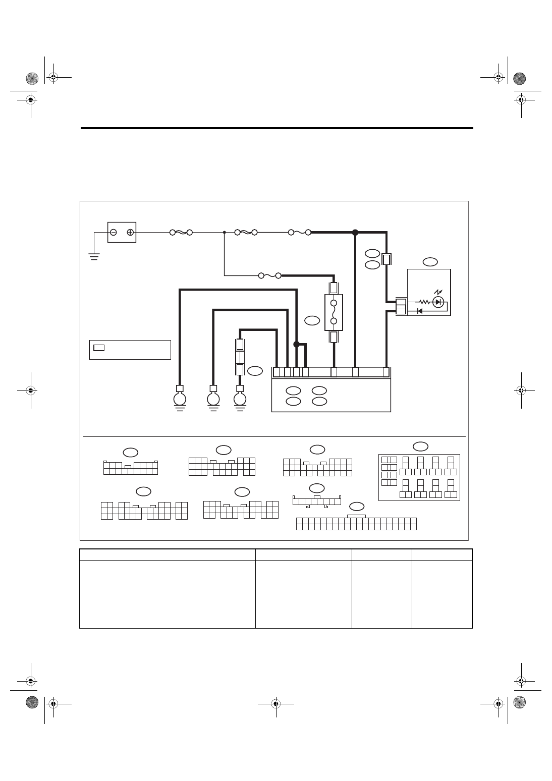
Diagnostics Chart for Security Indicator Light
IMMOBILIZER (DIAGNOSTICS)
8. Diagnostics Chart for Security Indicator Light
A: INSPECTION
1. CHECK SECURITY INDICATOR LIGHT CIRCUIT
WIRING DIAGRAM:
Immobilizer system <Ref. to WI-158, WIRING DIAGRAM, Immobilizer System.>
Step
Check
Yes
No
1
CHECK FUSE.
1) Remove the ignition key from ignition
switch.
2) Check the fuse (M/B No. 8).
Is the fuse OK?
Replace the fuse. If
the replaced fuse
blows out easily,
repair the short cir-
cuit in the harness
between the fuse
and body inte-
grated unit.
2 3 4 5
1
6 7 8
i97
1
*
i97
1
*
1
*
B225
13
14
15 16
17
27
24
25
26
20
21
22
23
29
30
31
28
32 35
33
34
37
38
39
36
40
8
9
10
11 12
1
2
5
3
4
7
6
19
18
3
4
10A
B225
B6
i10
1 2 3 4 5 6 7 8 9 10 11 12 13 14 15 16 17 18 19 20
21 22 23 24 25 26 27 28 29 30 31 32 33 34 35 36 37 38 39 40
B: B280
5
4
6
7 8
2
1
9
3
0
1
22 23
1
1
2
1
3
1
4
1
5
1
24
25 26
6
1
7
1
8
1
9
1
0
2
1
2
A2
8
D: B279
IM-00378
16
15
14
13
12
11
10
9
8
7
6
5
4
3
2
1
i102
i102
R167
2
D:
C:
A:
B279
30
21
20
19
29
28
18
17
16
27
26
25
24
15
14
13
12
11
23
22
10
3
9
1 2
8
7
6
4 5
35
34
33
32
31
30
29
28
27
26
25
24
23
22
21
20
19
18
17
16
15
14
13
12
11
10
9
8
7
6
5
4
3
2
1
i84
B281
21
20
19
18
17
16
28
27
26
15
14
13
12
11
25
23
22
24
10
3
4
9
1 2
8
7
6
5
C: B281
B: B280
A:
i84
D27
1
39
B17
C20
C2
A10
i10
E
E
E
SBF-8
MAIN SBF
BATTERY
COMBINATION
METER
BODY INTEGRATED
UNIT
M/B No. 8
FUSE
(RELAY
BLOCK)
SECURITY/
IMMOBILIZER
INDICATOR
LIGHT
RELAY BLOCK
JOINT GR
OUND
CONNECT
OR
: TERMINAL No. OPTIONAL
ARRANGEMENT
F/B No. 7