Subaru Impreza 3 / Impreza WRX / Impreza WRX STI. Manual - part 725
 

  Index      Subaru     Subaru Impreza 3 / Impreza WRX / Impreza WRX STI - service repair manual 2008-2014 year


Search            


Content   ..  723  724  725  726   ..


Subaru Impreza 3 / Impreza WRX / Impreza WRX STI. Manual - part 725


SL-49

Transmitter

SECURITY AND LOCKS

23.Transmitter

A: REMOVAL

1. TRANSMITTER BATTERY

CAUTION:

To prevent static electricity damage to the key-

less transmitter printed circuit board, touch the

steel  area  of  building  with  hand  to  discharge

static electricity carried on body or clothes be-

fore disassembling the keyless transmitter.

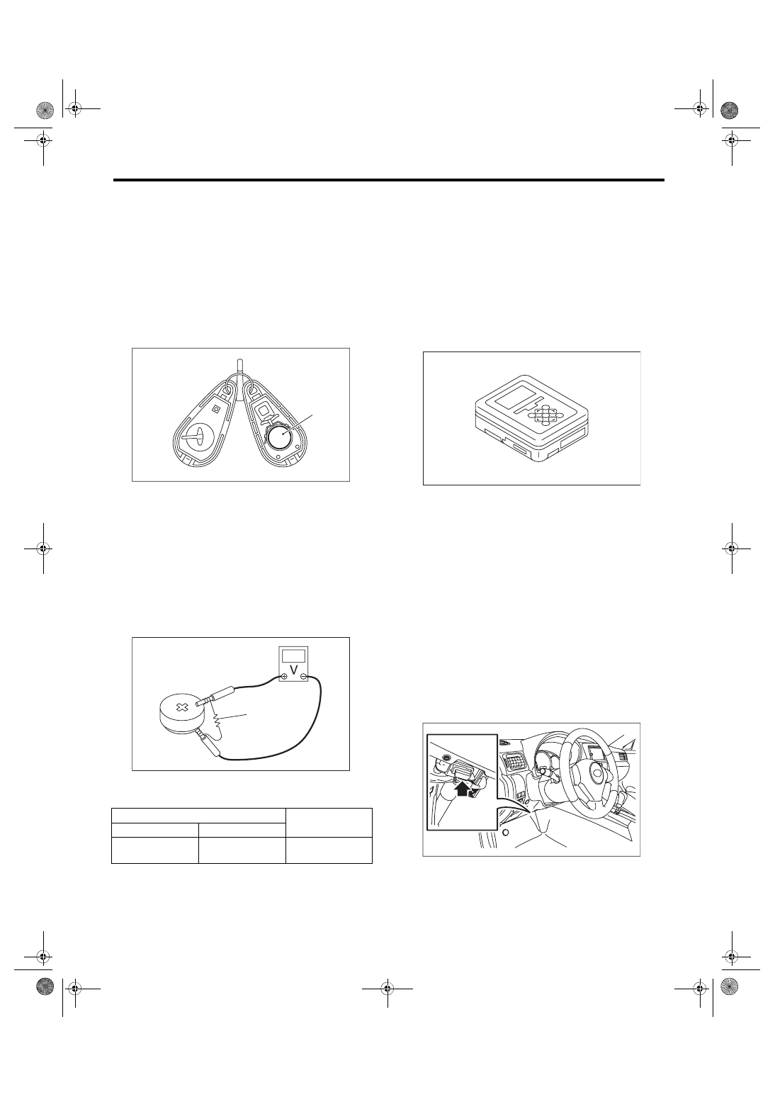
Remove the battery (1) from the transmitter.

B: INSTALLATION

Install each part in the reverse order of removal.

C: INSPECTION

1. TRANSMITTER BATTERY

1) Check the voltage between the transmitter bat-

tery (+) terminal and (–) terminal.
NOTE:

Battery  discharge  occurs  during  the  inspection.

Complete the measurement within 5 seconds.

2) Replace the battery if the inspection result is not

within the standard value. (Use CR2025 or equiva-

lent.)

D: REPLACEMENT

1. REGISTRATION OF KEYLESS TRANS-

MITTER WITH SUBARU SELECT MONITOR

NOTE:

• A  maximum  of  four  keyless  transmitter  can  be

registered for each individual vehicle.

• When replacing or adding the keyless transmit-

ter, new registration of transmitter is necessary.

1) Prepare the Subaru Select Monitor kit. <Ref. to

SL-7,  SPECIAL  TOOL,  PREPARATION  TOOL,

General Description.>

2) Prepare  PC  with  Subaru  Select  Monitor  in-

stalled.

3) Connect the USB cable to SDI (Subaru Diagno-

sis Interface) and USB port on the personal com-

puter  (dedicated  port  for  the  Subaru  Select

Monitor).
NOTE:

The dedicated port for the Subaru Select Monitor

means the USB port which was used to install the

Subaru Select Monitor.

4) Connect the diagnosis cable to SDI.

5) Connect SDI to data link connector located in the

lower portion of the instrument panel (on the driv-

er’s side).
CAUTION:

Do not connect scan tools other than the Suba-

ru Select Monitor.

6) Start the PC.

7) Turn the ignition switch to ON (engine OFF) and

run the “PC application for Subaru Select Monitor”.

(A) Resistance 47 Ω

Tester connection

Standard

(+)

(–)

Battery

Positive terminal

Battery

Ground terminal

2.5 — 3.0 V

(1)

SL-00387

(A)

SL-00066

EN-05692

EN-06148

SL-50

Transmitter

SECURITY AND LOCKS

8) On the «Main Menu» of the Subaru Select Mon-

itor, select the {Each System Check} → {Integ. unit

mode} → {Keyless ID registration}.

9) Input the 8-digit ID number attached to the tag

plate  of  the  transmitter  or  inside  the  transmitter,

from left to right. Press the [OK] key.

10) The  ID  number  you  have  entered  will  be

shown. Make sure that the ID number shown is the

same as that of plastic bag or inside of transmitter.

11) Press the [OK] key if the ID number is correct.

Press  the  [EXIT]  key  if  incorrect,  to  return  to  the

step 3) and enter the ID number again.

12) «ID is being registered···» is displayed and reg-

istration starts.

13) «ID registration completed » will be displayed

when the registration process is done.

14) To exit, select «Quit: NO» to return to {Keyless

ID  registration}.  If  there  are  additional  keyless

transmitters to be registered, select «The following

are registered: OK» to return to the step 4).
NOTE:

• If the registration  fails, «ID  cannot  register. Try

again.» will be shown. Select the [OK] key to return

to the {Keyless ID registration}. Retry starting from

the step 3).

• «Quit: NO» is shown on the Subaru Select Mon-

itor when fourth keyless transmitter has been regis-

tered. Select the [NO] key to return to {Keyless ID

registration}.

SL-51

Immobilizer Control Module

SECURITY AND LOCKS

24.Immobilizer Control Module

A: NOTE

The control of immobilizer system is carried out in

body  integrated  unit.  Refer  to  the  section  on  the

body integrated unit for the work procedures.

• Removal: <Ref. to SL-48, REMOVAL, Body Inte-

grated Unit.>

• Installation:  <Ref.  to  SL-48,  INSTALLATION,

Body Integrated Unit.>

SL-52

Immobilizer Antenna

SECURITY AND LOCKS

25.Immobilizer Antenna

A: REMOVAL

1) Disconnect the ground cable from battery.

2) Remove  the  screws  and  remove  the  steering

column cover lower.

3) Remove the harness cover lock.

4) Remove the screws and detach the knee protec-

tor.

5) Remove  the  screws  and  remove  the  steering

column cover upper.

6) Remove the instrument panel lower cover. <Ref.

to EI-49, REMOVAL, Instrument Panel Lower Cov-

er.>

7) Disconnect  the  immobilizer  antenna  connector

(A) and ignition switch lighting connector (B).

8) Loosen the screw and release the lock (D) at op-

posite side using flat tip screwdriver (1), and then

detach the immobilizer antenna (C).
CAUTION:

Do not apply excessive force to remove the im-

mobilizer  antenna  and  lock.  Otherwise  they

may  be  broken  because  those  parts  are  the

products made of a plastic.

B: INSTALLATION

Install each part in the reverse order of removal.

WW-00547

LI-01143

WW-00669

(D)

(1)

SL-00315

(A)

(C)

(B)


Content   ..  723  724  725  726   ..